TPE Di4000 User manual


DISCLAIMERS:
All information, illustrations and specications in this manual are based on the latest information available at the time of
publishing. The illustrations used in this manual are intended as representative reference views only. Moreover, because
of our continuous product improvement policy, we may modify information, illustrations and/or specications to explain
and/or exemplify a product, service or maintenance improvement. We reserve the right to make any change at any time
without notice. Some images may vary depending upon which model is shown.
ALL RIGHTS RESERVED:
No part of this publication may be reproduced or used in any form by any means – graphic, electronic or mechanical,
including photocopying, recording, taping or information storage and retrieval systems – without the written permission
of MWE Investments LLC.
DANGER
This manual contains important instructions for operating this generator. For your safety and the safety of others,
be sure to read this manual thoroughly before operating the generator. Failure to properly follow all instructions and
precautions can cause you and others to be seriously hurt or killed.
Model
Number
Running
Watts Peak Watts
Gasoline
Tank
Size (G)
Rated
Speed
(RPM)
Ignition
Type
Spark
plug
Engine
Disp (cc)
Stroke
X Bore
Oil
Capacity
(L) Oil Type
Fuel
Type
TPE Di4000 3500 4000
10L/2.65G
3600 TCI F7RTC 212cc 55X70 0.6 L 10W30 < 3%
NOTICE
This generator is NOT equipped with altitude carburetor modication. Even with a carburetor modication, engine horsepower will
decrease about 3.5% for each 300 meter (1,000 foot) increase in altitude. The eect of altitude on horsepower will be greater if no
carburetor modication is made. A decrease in engine horsepower will decrease the power output of the generator. Contact our
service team to order altitude kits.
FOR YOUR RECORDS:
Date of Purchase:
Inverter Model Number:
Purchased from Store/Dealer:
Inverter Serial Number:
TPE TECHNICAL SPECIFICATIONS
Operating, servicing and maintaining this equipment can expose you to chemicals including
engine exhaust, carbon monoxide, phthalates, and lead, which are known to the State
of California to cause cancer and birth defects or other reproductive harm. To minimize
exposure, avoid breathing exhaust, do not idle the engine except as necessary, service your
equipment in a well-ventilated area and wear gloves or wash your hands frequently when
servicing your equipment. For more information go to www.P65Warnings.ca.gov.
WARNING
2

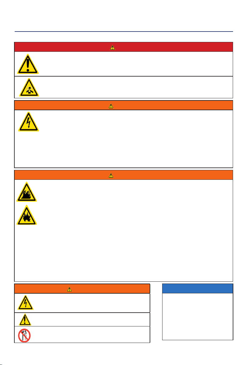
SAFETY DEFINITIONS
The words DANGER, WARNING, CAUTION and
NOTICE are used throughout this manual to highlight
important information. Be certain that the meanings of
these alerts are known to all who work on or near the
equipment.
This safety alert symbol appears
with most safety statements. It
means attention, become alert, your
safety is involved! Please read and
abide by the message that follows
the safety alerts symbol.
DANGER
Indicates a hazardous situation which, if not
avoided, will result in death or serious injury.
WARNING
Indicates a hazardous situation which, if not
avoided, could result in death or serious injury.
CAUTION
Indicates a hazardous situation which, if not
avoided, could result in minor or moderate injury.
NOTICE
Indicates a situation which can cause damage
to the generator, personal property and/or the
environment, or cause the equipment to operate
improperly.
NOTE:
Indicates a procedure, practice or condition
that should be followed in order for the
generator to function in the manner intended.
SAFETY
SAFETY SYMBOL DEFINITIONS
3
DANGER
Never use the inverter in a location that is wet or damp. Never expose the inverter to rain, snow,
water spray or standing water while in use. Protect the inverter from all hazardous weather conditions.
Moisture or ice can cause a short circuit or other malfunction in the electrical circuit.
Never operate the inverter in an enclosed area. Engine exhaust contains carbon monoxide. Only
operate the inverter outside and away from windows, doors and vents.
WARNING
Voltage produced by the inverter could result in death or serious injury.
• Never operate the inverter in rain or a ood plain unless proper precautions are taken to avoid being
subject to rain or a ood.
• Never use worn or damaged extension cords.
• Always have a licensed electrician connect the inverter to the utility circuit.
• Never touch an operating inverter if the inverter is wet or if you have wet hands.
•Never operate the inverter in highly conductive areas such as around metal decking or steel works.
• Always use grounded extension cords. Always use three-wire or double-insulated power tools.
• Never touch live terminals or bare wires while the inverter is operating.
• Be sure the inverter is properly grounded before operating.
WARNING
Gasoline, gasoline vapors & liquid petroleum gas (LPG) are extremely ammable and explosive under
certain conditions.
• Always refuel the generator outdoors, in a well-ventilated area.
• Never remove the fuel cap with the engine running.
• Never refuel the inverter while the engine is running. Always turn engine o and allow the generator to
cool before refueling.
• Only ll fuel tank with gasoline.
• Keep sparks, open ames or other forms of ignition (such as match, cigarette, static electric source)
away when refueling.
• Never overll the fuel tank. Leave room for fuel to expand. Overlling the fuel tank can result in a
sudden overow of gasoline and result in spilled gasoline coming in contact with HOT surfaces.
Spilled fuel can ignite. If fuel is spilled on the inverter, wipe up any spills immediately. Dispose of rag
properly. Allow area of spilled fuel to dry before operating the inverter.
• Wear eye protection while refueling.
• Never use gasoline as a cleaning agent.
• Store any containers containing gasoline in a well-ventilated area, away from any combustibles or
source of ignition.
• Check for fuel leaks after refueling. Never operate the engine if a fuel leak is discovered.
WARNING
Never operate the inverter if powered items overheat,
electrical output drops, there is sparking, ames or smoke
coming from the inverter, or if the receptacles are damaged.
Never use the inverter to power medical support equipment.
Always remove any tools or other service equipment used
during maintenance from the inverter before operating.
NOTICE
Never modify the inverter.
Never operate the inverter if it
vibrates at high levels, if engine
speed changes greatly or if the
engine misres often.
Always disconnect tools or
appliances from the
inverter before starting.
GENERAL SAFETY RULES
SAFETY
4

FEATURES
TPE Di4000 FEATURES
Open frame inverter design: Quiet, fuel ecient
power provided by a digital inverter built in a
rugged open frame design.
Choke lever: Pull to choke and push in to run
once the engine has started.
Oil Fill Plug/Dipstick: Must be removed to add
and check oil.
Muer and Spark Arrestor: Avoid contact until
the engine is cooled down. The spark arrestor
prevents sparks from exiting the muer. It must be
removed for servicing.
Recoil Handle: Pull to start the engine.
Air-lter Access Cover: Gain access to air-lter
for maintenance.
Fuel Gauge: Indicates fuel level.
1
5
6
7
2
3
4
1
4
5
23
6
7
5
Table of contents
Popular Inverter manuals by other brands


BARRON
BARRON EXITRONIX Tucson Micro Series installation instructions

Baumer
Baumer HUBNER TDP 0,2 Series Mounting and operating instructions

electroil
electroil ITTPD11W-RS-BC Operation and Maintenance Handbook

Silicon Solar
Silicon Solar TPS555-1230 instruction manual

Mission Critical
Mission Critical Xantrex Freedom SW-RVC owner's guide

HP
HP 3312A Operating and service manual


