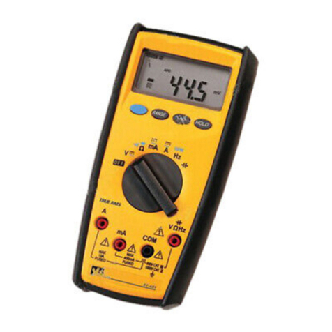
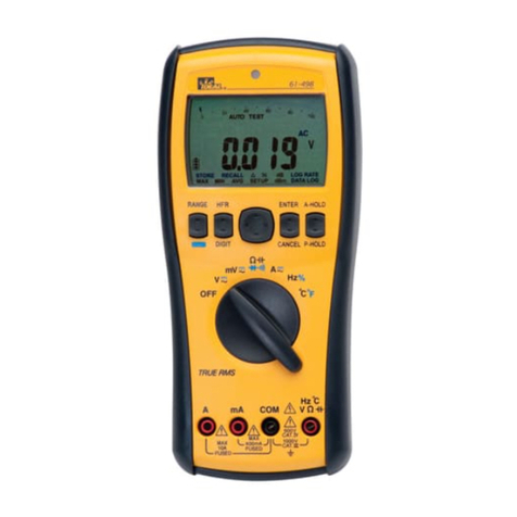
IDEAL 61-497 User manual

2
#61-497
#61-498
Digital Multimeter
Instruction Manual
Read First: Safety Information
Understand and follow operating instructions carefully. Use the meter
only as specified in this manual; otherwise, the protection provided by
the meter may be impaired.
WARNING
To avoid possible electric shock, personal injury or death, follow these
guidelines:
•Donotuseifmeterappearsdamaged.Visuallyinspectthemeterto
ensure case is not cracked and back case is securely in place.
•Inspectandreplaceleadsifinsulationisdamaged,metalisexposed,
or probes are cracked. Pay particular attention to the insulation
surrounding the connectors.
•Donotusemeterifitoperatesabnormallyasprotectionmaybeimpaired.
•Donotuseduringelectricalstormsorinwetweather.
•Donotusearoundexplosivegas,dust,orvapor.
•Donotapplymorethantheratedvoltagetothemeter.
•Donotusewithoutthebatteryandthebackcaseproperlyinstalled.
•Replacebatteryassoonasbatteryindicatorappearstoavoidfalse
readings.
•Removethetestleadsfromthecircuitpriortoremovingbatterycover.
•Donotattempttorepairthisunitasithasnouser-serviceableparts.
CAUTION
To protect yourself, think “Safety First”:
•Voltagesexceeding30VACor60VDCposeashockhazardsouse
caution.
•Useappropriatepersonalprotectiveequipmentsuchassafetyglasses,
face shields, insulating gloves, insulating boots, and/or insulating
mats.
•Beforeeachuse:
- Performacontinuitytestbytouchingthetestleadstogetherto
verify the functionality of the battery and test leads.
- Usethe3PointSafetyMethod.(1)Verifymeteroperationby
measuringaknownvoltage.(2)Applymetertocircuitunder
test.(3)Returntotheknownlivevoltageagaintoensureproper
operation.
•Usetheproperterminals,functionsandrangeforyourmeasurements.
•Nevergroundyourselfwhentakingelectricalmeasurements.
•Connecttheblackcommonleadtogroundorneutralbeforeapplying
theredtestleadtopotentialvoltage.Disconnecttheredtestleadfrom
the voltage first.
•Alwaysworkwithapartner.
•Whenusingtheprobes,keepfingersasfarbehindtheprobetipsas
possible.
kMΩHz
G’F’C%
µmVAF
ACDC LVΩ
AutoPeak HOLD
RS232
HFR
OFF
MAX
10A
FUSED
MAX
mA
FUSED
600V
CAT IV
1000V
CAT III
AmACOM V
Hz °C
°C°F
V Hz%
mV A
MAX-MIN
FH AVG
AC+DC
STORE RECALL dB
dBm LOG RATE
DATA LOG
MAX MINAVG SETUP
RANGE
DIGIT CANCEL P-HOLD
HFR EBTER A-HOLD

3 4
Symbols as marked on the meter and instruction manual
Unsafe Voltage
Toalertyoutothepresenceofapotentiallyhazardousvoltage,whenthe
Tester detects a voltage ≥30Voravoltageoverload(OL)inV,mV.The
“ “ symbol is displayed and High voltage indicator is activated.
Riskofelectricshock
See instruction manual
DCmeasurement
Equipmentprotectedbydoubleorreinforcedinsulation
Battery
Fuse
Earth
ACmeasurement
ConformstoEUdirectives
Donotdiscardthisproductorthrowaway
The Meter Description
FrontPanelIllustration
1. LCDdisplay:4000/40000countsfor61-497.
10000/100000countsfor61-498.
2. Push-buttons.
3. RotaryswitchtoturnthePowerOn/Offandselectthefunction.
4. InputTerminalforA.
5. InputTerminalforV,Ω,@,Hz,°Cfunctions.
6. Common(Groundreference)InputTerminal.
7. InputTerminalformA.
kMΩHz
G’F’C%
µmVAF
ACDC LVΩ
AutoPeak HOLD
RS232
HFR
OFF
MAX
10A
FUSED
MAX
mA
FUSED
600V
CAT IV
1000V
CAT III
AmACOM V
Hz °C
°C°F
V Hz%
mV A
MAX-MIN
FH AVG
AC+DC
STORE RECALL dB
dBm LOG RATE
DATA LOG
MAX MINAVG SETUP
RANGE
DIGIT CANCEL P-HOLD
HFR EBTER A-HOLD
1 Display
2 Buttons
3 Rotary Switch
5 V, Ω, , HZ, °C
Input
6 Common Input
7 mA Input
4 A Input

5 6
Making Basic Measurements
PreparationandCautionBeforeMeasurement
:ObservetherulesofWarningsandCautions
WhenconnectingthetestleadstotheDUT(DeviceUnderTest)connect
thecommon(mA)testleadbeforeconnectingthelivelead.When
removing the test leads remove the live test lead before removing the
common test lead.
The figures on the following pages show how to make basic
measurements.
Measuring AC / DC Voltage
High Frequency Reject mode
TheHFRmodemakesthevoltagepassthroughalowpassfilterto
rejectthehighfrequency.The–3dBpointofthelowpassfilteris800
Hz.WhentherotaryswitchisinV,mVposition,theHFRmodecanbe
used.TouseHFRmode,presstheHFRbutton.
Measuring Resistance / Continuity / Diode Capacitance
kMΩHz
G’F’C%
µmVAF
ACDC LVΩ
AutoPeak HOLD
RS232
HFR
OFF
MAX
10A
FUSED
MAX
mA
FUSED
600V
CAT IV
1000V
CAT III
AmACOM V
Hz °C
°C°F
V Hz%
mV A
MAX-MIN
FH AVG
AC+DC
STORE RECALL dB
dBm LOG RATE
DATA LOG
MAXMIN AVG SETUP
RANGE
DIGIT CANCEL P-HOLD
HFR EBTER A-HOLD
+
+–
–
+–
~
AUTO TEST
AUTO TEST
DC
V
AC
V
V
AUTO TEST
~
mV
~
Press the function button to select the measuring function
(AC/DC/AC+DC).
AUTO
AUTO
AUTO TEST
AUTO TEST
Press ≥ 2 Sec.
µF
V
1
4
3
5
5
1234
2
OFF
MAX
10A
FUSED
MAX
mA
FUSED
600V
CAT IV
1000V
CAT III
A mA COM V
Hz °C
°C°F
V Hz%
mV A
+–
Press the function button to select the measuring function.
(Ω///)
Testing Continuity
+–+–

7 8
Testing Diode Measuring Frequency
Measuring AC/DC Current
Press the function button to select the measuring function
(AC/DC/AC+DC).
Press the function button to select the measuring function.
(Period/Duty)
Measuring Temperature °C / °F
Press the function button to select the measuring function.
(°C/°F)
+–+–
+–
VV
kMΩHz
G’F’C%
µmVAF
ACDC LVΩ
AutoPeak HOLD
RS232
HFR
OFF
MAX
10A
FUSED
MAX
mA
FUSED
600V
CAT IV
1000V
CAT III
AmACOM V
Hz °C
°C°F
V Hz%
mV A A
MAX-MIN
FH AVG
AC+DC
STORE RECALL dB
dBm LOG RATE
DATA LOG
MAXMIN AVG SETUP
RANGE
DIGIT CANCEL P-HOLD
HFR EBTER A-HOLD
+
DISCONNECT
–
–
kMΩHz
G’F’C%
µmVAF
ACDC LVΩ
AutoPeak HOLD
RS232
HFR
OFF
MAX
10A
FUSED
MAX
mA
FUSED
600V
CATIV
1000V
CATIII
AmACOM V
Hz °C
°C°F
V Hz%
mV A A
MAX-MIN
FH AVG
AC+DC
STORE RECALL dB
dBm LOG RATE
DATA LOG
MAXMIN AVG SETUP
RANGE
DIGIT CANCEL P-HOLD
HFR EBTER A-HOLD
+
DISCONNECT
–
–
kMΩHz
G’F’C%
µmVAF
ACDC LVΩ
AutoPeak HOLD
RS232
HFR
OFF
MAX
10A
FUSED
MAX
mA
FUSED
600V
CAT IV
1000V
CAT III
AmACOM V
Hz °C
°C°F
V Hz% Hz%
mV A
MAX-MIN
FH AVG
AC+DC
STORE RECALL dB
dBm LOG RATE
DATA LOG
MAXMIN AVG SETUP
RANGE
PRESS
DIGIT CANCEL P-HOLD
HFR EBTER A-HOLD
+–
~
µs
kHz
%
kHz
kMΩHz
G’F’C%
µmVAF
ACDC LVΩ
AutoPeak HOLD
RS232
HFR
OFF
MAX
10A
FUSED
MAX
mA
FUSED
600V
CATIV
1000V
CATIII
AmACOM V
Hz °C
°C°F
°C°F
V Hz%
mV A
MAX-MIN
FH AVG
AC+DC
STORE RECALL dB
dBm LOG RATE
DATA LOG
MAXMIN AVG SETUP
RANGE
DIGIT CANCEL P-HOLD
HFR EBTER A-HOLD
PRESS
Sensor K Type
Vent
or
Pipe
°C
°F
°C
°F
+
–

9 10
DIGIT:
AUTO HOLD:
Peak HOLD (ACV / ACA Only)
Sub-Functions navigation option
Sub-Functions item
Buttons
Navigation: Select the Sub-function item.
ENTER: Enter the Sub-function.
CANCEL: Exit the function.
ENTER
CANCEL
PresstheDIGITbuttontoselectthedisplaydigit.
InthePeakHoldfunction,themeterrecordsthepeakmaximum
valueandthepeakminimumvalue.Whentheinputsgobelowthe
recordedpeakminimumvalueorabovetherecordedpeakmaximum
value,themeterrecordsthenewvalue.TousethePeakHOLDmode,
presstheP-HOLDbutton.
IntheAutoHoldfunction,themeterholdsthereading,andthe
currentreadingappearsontheupperdisplay.Whenthedifferenceof
theholdvalueandthecurrentvalueisabove20counts,themeter
beepsandholdsthenewvalue.TousetheAutoHoldmode,pressthe
A-Holdbutton.
kHz
AUTO
DIGIT
Press
V
AC
Press
A-Hold
STORE RECALL dB
dBm LOG RATE
DATA LOG
MAX MINAVG SETUP
kHz
AUTO
V
AC
STORE RECALL dB
dBm LOG RATE
DATA LOG
MAX MINAVG SETUP
kHz
AUTO
V
AC
STORE RECALL dB
dBm LOG RATE
DATA LOG
MAX MINAVG SETUP
V
AUTO HOLD
AUTO
V
AC
kHz
AUTO
DIGIT
Press
V
AC
Press
A-Hold
STORE RECALL dB
dBm LOG RATE
DATA LOG
MAX MINAVG SETUP
kHz
AUTO
V
AC
STORE RECALL dB
dBm LOG RATE
DATA LOG
MAX MINAVG SETUP
kHz
AUTO
V
AC
STORE RECALL dB
dBm LOG RATE
DATA LOG
MAX MINAVG SETUP
V
AUTO HOLD
AUTO
V
AC
kHz
AUTO
V
AC
kHz
V
AC
AUTO
Peak Hold
V
AC
AUTO MAXMIN
Peak Hold
V
VAC
Press
Press
P-Hold
Press
>25 sec
Press
>25 sec
STORE RECALL dB
dBm LOG RATE
DATA LOG
MAX MIN AVG SETUP

11 12
1. Store and Recall 2. MAX / MIN / AVG
The store function records the input values to memory and recalls
themfrommemory.Themaximumrecordedrecordsinmemory
are1000.
TheMAX/MIN/AVGmoderecordstheminimumandmaximuminput
values.Whentheinputsgobelowtherecordedminimumvalue
orabovetherecordedmaximumvalue,themeterrecordsthenew
value.TheMAX/MIN/AVGmodecanalsocalculatetheaverageofthe
maximumvalueandtheminimumvalue.
DC
V
DC
V
PRESS
ENTER
DC
V
PRESS
ENTER
Last
Data
Press
Next
Data
Press
DC
V
DC
V
PRESS
PRESS
ENTER
STORE
ENTER
CANCEL
STORE
STORE
STORE
DC
V
RECALL
RECALL
ENTER
DC
V
DC
MAX
V
PRESS PRESS PRESS PRESS
Cancel
MAX MIN AVG
DC
AVG
V
MAX MIN AVG
DC
MIN
V
MAX MIN AVG

13 14
3. dB and dBm (ACV / ACmV only) 4. Relative mode
Intherelativemode,themeterrecordsthecurrentinputvalueas
reference and appears on the upper display. The after input values
willcalculatethedifference()ofthereferencevalueandtheinput
valueorthedifferencepercent(%)ofthereferencevalueandthe
input value.
Thedecibel(dB)isalogarithmicunitofmeasurementthatexpresses
themagnitudeofaphysicalquantityrelativetoaspecifiedorimplied
referencelevel.ThedBanddBmaredefinedbelow.
dB=20log
dBm=20log
VAC
1
VAC
0.7746
AC
AUTO kHz
VENTER
CANCEL
PRESS
PRESS
PRESS
dB
dBm
AC
AUTO
dB
V
dB
dB
AC
AUTO
dB
V
dBm
dBm
dB
dBm
AC
AUTO
VENTER
PRESS
CANCEL
PRESS
AC 2V
PRESS
AC
V
V
AC
V
V
OFF
MAX
10A
FUSED
MAX
mA
FUSED
600V
CATIV
1000V
CATIII
AmACOM V
Hz °C
°C°F
VHz%
mV A
AC 3V
OFF
MAX
10A
FUSED
MAX
mA
FUSED
600V
CATIV
1000V
CATIII
AmACOM V
Hz °C
°C°F
VHz%
mV A
AC 3V
OFF
MAX
10A
FUSED
MAX
mA
FUSED
600V
CATIV
1000V
CATIII
AmACOM V
Hz °C
°C°F
VHz%
mV A

15 16
5.4 HAZARD
Setupthebeepertothedangerousvoltage(≥60VDC or ≥30VAC)sense
modeeitherONorOFF.
5.5 RESET
Resetallsetupvaluestodefault.
5.6 LOG RATE
Setupthelogratefrom0.5to600seconds.
5.7 DATALOG
The datalog mode records the successive input values to memory and
recallsthemfrommemorylater.Themaximumrecordedrecordsin
memoryare20000.
SETUP SETUP
SETUP SETUP
SETUP SETUP
SETUP SETUP
PRESS
PRESS
5. SETUP Option
Press or to change the meter setting.
PressENTERtostorethesettinginmemory.
Press or to select the meter setting item.
PressCANCELtoexitthisfunction.
5.1 Beeper
SetupthebeepertoONorOFF.
5.2 Auto Power Off
SetuptheAPOtimefrom1to60minutesorOFF.
5.3 Back Light Auto OFF
SetupthebacklightAutoOFFtimefrom1to60minutes.
SETUP SETUP
SETUP SETUP
SETUP SETUP
SETUP SETUP
PRESS
PRESS
SETUP SETUP
SETUP SETUP
SETUP SETUP
SETUP SETUP
PRESS
PRESS
SETUP SETUP SETUP SETUP
PRESS
PRESS
SETUP SETUP
ENTER
PRESS
PRESS
CANCEL
PRESS
DC
V
LOG RATE
DC
V
LOG RATE
LOG
RATE
LOG
RATE
DC
V
LOG RATE
LOG
RATE

17 18
Auto Power Off
Wake-upthemeterbyswitchingtherotororpressinganybutton.
Auto Backlight
The backlight is automatically turned on in dark environments.
BUZZER
Themeterbeepsonceforeveryvalidkey-press,andbeepstwicefor
everyinvalidkey-press.
Power On Options
PressthebuttonwhileturningthemeteronfromOFFposition.
Cancel button : Clearallstoreddata
Range button : DisplayLCDtestframe
Function button : Default°C/°Freading
HFR button :Displayfirmwareversion
A-HOLD button : DisableAUTOBACKLIT
Battery and Fuse Replacement
Refertothefollowingfiguretoreplacethefuseandbatteries:
CAUTION
•Useonlyafusewiththeamperage,interrupt,voltageandspeed
rating specified.
•Fuserating: 440mA,1000VIR10KAFuse(size35x10mm)
11A1000VIR20KAFuse(size38x10mm)
•Toavoidafalsereading,replacethebatteriesassoonasthelow
battery indicator appears.
•1.5Vx4alkalinebatteries.
Maintenance
Cleanthecasewithadampclothandmilddetergent.Donotuse
abrasives or solvents.
Service and Replacement Parts
Nouser-serviceableparts.
Forreplacementpartsortoinquireaboutserviceinformation,contact
IDEALINDUSTRIES,INC.at1-877-201-9005orvisitourwebsite@
www.testersandmeters.com.
AUTOTEST
AC
V
OFF
RANGE
DIGIT CANCEL P-HOLD
HFR EBTER A-HOLD RANGE
DIGIT CANCEL P-HOLD
HFREBTER A-HOLD
V
20min
AUTO
KΩ
AUTO
KΩ
AUTO
BACKLIT

19 20
Specifications
General Specifications
Maximum voltage applied
to any terminal: 1000Vacrmsordc
Display 4000/40000countsfor61-497
10000/100000countsfor61-498
Polarity Indication: OL
Batteries Life: 100hours
Low Batteries Indication: “ “ is displayed when the batteries voltage
drops below operating voltage
Low battery voltage: Approx.4.5V
AUto Power Off: Default30minutes
Operating Ambient: Non-condensing≤10°C
11°C~30°C(≤80%RH),
30°C~40°C(≤75%RH),
40°C~50°C(≤45%RH),
Storage Temperature: -20°Cto60°C,0to80%R.H.
(batteriesnottted)
Temperature oefficient: 0.15x(Spec.Accy)/°C,<18°Cor>28°C
Measure Samples3timespersecondnormal
Altitude 6561.7ft.(2000m)
Safety ComplieswithEN61010-1,UL61010-1,
IEC61010-1,CATIV600V,CATIII1000V
CAT ApplicationFIeld
IThe circuits not connected to mains
II The circuits directly connected to
Low-voltageinstallation
III The building installation
IV ThesourceoftheLow-voltageinstallation
Weight: (630g)includingbattery.
Dimensions (W x H x D) 95mmx207mmx52mmwithholster.
Accessories: Battery(installed),Testleadsanduser
manual.(Theprobeassemblyprovidedwith
theproductisforusewiththismeteronly)
Power Requirements: 1.5Vx4IECLR6orAAsize.
Pollution degree: 2
EMC EN61326-1
Shock vibration: SinusoidalvibrationperMIL-T-28800E
(5~55Hz,3gmaximum).
Drop Protection 4ft.droptohardwoodonconcreteoor.
Indoor Use.
61-497
Range Frequency Accuracy
40.000mVDC
–
±(0.040%+40d)
400.00mVDC ±(0.035%+20d)
4.0000VDC
40.000VDC
400.00VDC
1000.0VDC
±(0.03%+20d)
40.000mVAC
400.00mVAC
40Hz~65Hz ±(1.00%+50d)[1]
66Hz~1KHz ±(3.00%+50d)[1]
1.01KHz~3KHz ±(5.00%+50d)[2]
4.0000VAC
40.000VAC
400.00VAC
1000.0VAC
40Hz~45Hz ±(1.50%+50d)[1]
46Hz~65Hz ±(0.70%+50d)[1]
66Hz~1KHz ±(1.50%+50d)[1]
4.0000VAC
40.000VAC
1.01KHz~10KHz ±(3.00%+50d)[2]
10.01KHz~50KHz ±(5.00%+50d)[3]
50.01KHz~100KHz ±(10.0%+50d)[3]
Compliance to EN 61557 : IEC61557-1, IEC61557-2,
IEC61557-4, IEC61557-10
Electrical Specifications
Accuracyis±(%reading+numberofdigits)at23°C±5°C
<80%RH.
(1) Voltage
Equipment protected by double insulation.
Instrumenthasbeenevaluatedandcomplieswithinsulation
(overvoltage)catergoryIV.Pollutiondegree2inaccordancewith
IEC-644.Indooruse.
21 22
Input Protection: 1000VDCor1000VAC rms
Bandwidth: 40Hz~100KHz
Minimum Resolution: 1µVinthe100mVrangeandthe40mVrange.
Input Impedance: 10MΩ,<100pF
CMRR / NMRR:
(Common Mode
Rejection Ratio)
(Normal Mode
Rejection Radio
VAC: CMRR>60dBatDC,50Hz/60Hz
VDC: CMRR>100dBatDC,50Hz/60Hz
NMRR>50dBatDC,50Hz/60Hz
AC Conversion Type: ACconversionsareac-coupled,truermsresponding,
Calibratedtothesinewaveinput.
Fornon-sinewaveaddthefollowingCrestFactorconditions:
ForCrestFactorof1.4to2.0,add1.0%toaccuracy.
ForCrestFactorof2.0to2.5,add2.5%toaccuracy.
ForCrestFactorof2.5to3.0,add4.0%toaccuracy.
AC + DC Accuracy: Add1.0%toaccuracy.
HFR Accuracy: Add1.0%toaccuracyat40Hz~400Hz
The cut-off frequency
of the High Frequency
Reject: 800Hz(-3dB)
dB/dBm: ±60dBm
Note: Forbestmeasurements,usetheRELfunctionto
compensate for offsets.
61-498
Range Frequency Accuracy
100.000mVDC
–
±(0.025%+40d)
1000.00mVDC ±(0.020%+20d)
10.0000VDC
100.000VDC
1000.00mVDC
±(0.015%+20d)
100.000mVAC
1000.00mVAC
40Hz~65Hz ±(0.70%+50d)[1]
66Hz~1KHz ±(1.50%+50d)[1]
1.01KHz~3KHz ±(3.00%+50d)[2]
10.0000VAC
100.000VAC
1000.00VAC
40Hz~45Hz ±(1.00%+50d)[1]
46Hz~65Hz ±(0.40%+50d)[1]
66Hz~1KHz ±(1.00%+50d)[1]
10.0000VAC
100.000VAC
1.01KHz~10KHz ±(2.00%+50d)[1]
10.01KHz~20KHz ±(3.00%+50d)[2]
20.01KHz~50KHz ±(5.00%+50d)[3]
50.01KHz~100KHz ±(10.0%+50d)[3]
[1]Below5%ofrange,add70counts.Below45Hz,<50dgtrolling.
[2]Below5%ofrange,add150counts.
[3]Below5%ofrange,add350counts.
Input Protection: EquippedwithHighEnergyFuse.
440mA,1000VIR10KAfuseformAinput.
11A,1000VIR20KAfuseforAinput.
Bandwidth: 40Hz~1KHz
Minimum Resolution: 1µVinthe40mVrangefor61-497,
0.1µAinthe10mArangefor61-498.
Maximum Measuring
Time: 3minutesatAinput,10minutesatmAinput.
Resttimeis20minutesminimum.
AC Conversion Type: Converstiontypeandadditionalspecicationsaresameas
voltage.
61-497
Range Frequency Accuracy
40.000mADC
400.00mADC –
±(0.2%+40d)
4.0000ADC
10.000ADC ±(0.2%+80d)
40.000mAAC
400.00mAAC
4.0000ADC
10.000AAC
40Hz~65Hz ±(0.8%+80d)[1]
66Hz~1KHz ±(3.0%+80d)[1]
61-498
Range Frequency Accuracy
10.0000mADC
100.000mADC –±(0.1%+40d)
10.0000ADC ±(0.1%+80d)
10.0000mAAC
100.000mAAC
10.0000AAC
40Hz~65Hz ±(0.7%+80d)[1]
66Hz~1KHz ±(2.0%+80d)[1]
[1]Below5%ofrange,add70counts.Below45Hz,<50dgtrolling.
(2) Current
(3) Peak Hold
Specifiedaccuracy±(3.0%+100d)upto50000count(fullrange)
range.

23 24
61-497
Range Resolution Accuracy
400.00Ω0.01Ω
±(0.2%+30d)4.0000KΩ0.1Ω
40.000KΩ1Ω
400.00KΩ10Ω±(0.3%+30d)
4.0000MΩ100Ω±(1.0%+30d)[1]
40.00MΩ10KΩ±(1.5%+30d)[1]
61-498
Range Resolution Accuracy
1000.00Ω0.01Ω±(0.05%+30d)
10.0000KΩ0.1Ω±(0.025%+30d)
100.000KΩ1Ω
1000.00KΩ10Ω±(0.3%+30d)
10.0000MΩ100Ω±(1.0%+30d)[1]
40.00MΩ10KΩ±(1.5%+30d)[1]
[1]<100dgtrolling.
61-497
Range Resolution Accuracy
400.0Ω0.1Ω±(0.2%+3d)
61-498
Range Resolution Accuracy
1000.0Ω0.1Ω±(0.05%+3d)
61-497
Range Resolution Accuracy
2.000V 1mV ±(1.5%+2d)
61-498
Range Resolution Accuracy
0.400V~0.800V 1mV ±(1.5%+2d)
(4) Resistance
(5) Continuity Check
(6) Diode Test
(7) Capacitance
Input Protection: 1000VDCor1000VAC rms
Maximum Open Circuit Voltage: Approximate2.5V
Maximum Test Current: Approximate0.1mA
Note:Forbestmeasurements,usetheRELfunctiontocompensateforoffsets.
Input Protection: 1000VDCor1000VAC rms
Maximum Open Circuit Voltage: Approximate2.5V
Maximum Test Current: Approximate0.1mA
Continuity Threshold: Approximate50Ω
Continuity Indicator: 2KHzToneBuzzer
Input Protection: 1000VDCor1000VAC rms
Maximum Open Circuit Voltage: Approximate±2.5V
Maximum Test Current: Approximate0.5mA
Input Protection: 1000VDCor1000VAC rms
Note:Forbestmeasurements,usetheRELfunctiontocompensateforoffsets.
61-497
Range Resolution Accuracy Measuring TIme
4.000nF 1pF ±(1.2%+40d)[1]
0.7sec.
40.00nF 10pF ±(1.2%+20d)
400.0nF 100pF
±(0.9%+2d)
4.000µF 1nF
40.00µF 10nF
400.0µF 100nF
4.000mF 1µF ±(1.2%+20d) 3.75sec.
40.00mF 10µF ±(1.2%+40d)[1] 7.5sec.
61-498
Range Resolution Accuracy Measuring TIme
4.000nF 1pF ±(1.2%+40d)[1]
0.7sec.
40.00nF 10pF ±(1.2%+20d)
400.0nF 100pF
±(0.8%+2d)
4.000µF 1nF
40.00µF 10nF
400.0µF 100nF
4.000mF 1µF ±(1.2%+20d) 3.75sec.
40.00mF 10µF ±(1.2%+40d)[1] 7.5sec.
[1]<50dgtrolling.

25
(8) Frequency Counter
(9) Duty Factory
(10) Temperature
(11) Frequency Counter with AC Function:
61-497 / 61-498
Range Resolution Accuracy Sensitivity
40.000Hz 0.001Hz ±(0.002%+50d)
1VP-P
400.00Hz 0.01Hz
±(0.002%+10d)
4.0000KHz 0.1Hz
40.000KHz 1Hz
400.00KHz 10Hz 5VP-P
4.0000MHz 100Hz
61-497 / 61-498
Range Resolution Accuracy Sensitivity
20.0%~80.0% 0.1% ±(0.1%+10d) 5VP-P
61-497 / 61-498
Range Resolution Accuracy
-200.0°C~10.0°C 0.1°C ±(1.0%+2°C)
10.1°C~1200.0°C ±(1.0%+1°C)
-328.0°F~50.0°F 0.1°F ±(1.0%+4°F)
50.1°F~2192.0°F ±(1.0%+2°F)
61-497 / 61-498
Range Accuracy Sensitivity
40.00KHz ±(0.1%+1d) 10%RangeCount
400.0KHz
Input Protection: 1000VDCor1000VAC rms
Min Frequency: 5Hz
Input Protection: 1000VDCor1000VAC rms
Sense Wave: SquareWave(5Hz~10KHz)
Input Protection: 1000VDCor1000VAC rms
Dispose of waste electrical and electronic equipment
Inordertopreserve,protectandimprovethequalityoftheenviron-
ment,protecthumanhealthandutilizenaturalresourcesprudentlyand
rationally, the user should return unserviceable product to relevant
facilitiesinaccordancewithstatutoryregulations.Thecrossed-out
wheeled bin indicates the product needs to be disposed separately and
not as municipal waste.
Disposal of used batteries/accumulators!
The user is legally obliged to return used batteries and accumula-
tors.Disposingusedbatteriesinthehouseholdwasteisprohibited!
Batteries/accumulatorscontaininghazardoussubstancesaremarked
withthecrossed-outwheeledbin.Thesymbolindicatesthatthe
product is forbidden to be disposed via domestic refuse. The chemi-
calsymbolsfortherespectivehazardoussubstancesareCd=
Cadmium,Hg=Mercury,Pb=Lead.
You can return used batteries/accumulators free of charge to any collecting
point of your local authority, our stores, or where batteries/accumulators are
sold.Consequentlyyoucomplywithyourlegalobligationsandcontributeto
environmental protection.
Warranty Statement:
This tester is warranted to the original purchaser against defects in material
andworkmanshipfortwoyearsfromthedateofpurchase.Duringthiswarranty
period,IDEALINDUSTRIES,INC.will,atitsoption,replaceorrepairthe
defective unit, subject to verification of the defect or malfunction. This warranty
doesnotapplytodefectsresultingfromabuse,neglect,accident,unauthorized
repair, alteration, or unreasonable use of the instrument.
AnyimpliedwarrantiesarisingoutofthesaleofanIDEALproduct,including
but not limited to implied warranties of merchantability and fitness for a
particular purpose, are limited to the above. The manufacturer shall not be
liableforlossofuseoftheinstrumentorotherincidentalorconsequential
damages,expenses,oreconomicloss,orforanyclaimorclaimsforsuch
damage,expensesoreconomicloss.
Statelawsvary,sotheabovelimitationsorexclusionsmaynotapplytoyou.
This warranty gives you specific legal rights, and you may also have other
rights which vary from state to state.
Warrantydoesnotcoverbatteriesortestleads.
Input Protection: 1000VDCor1000VAC rms
Min Frequency: 10Hz
Minimum Resolution: 10Hz

27 28
#61-497
#61-498
MULTÍMETRO DIGITAL
Manual de Instrucciones
Lea primeramente: Información de seguridad
Asegúresedeentenderyseguircuidadosamentelasinstruccionesdeoperación.
Useelinstrumentosólocomoseespecificaenestemanual.Delocontrario,la
protecciónqueproporcionaelmismopuedereducirse.
ADVERTENCIA
Paraevitarposiblesriesgosdeelectrocución,lesionesolamuerte,sigaestas
pautas:
• Nouseelinstrumentosielmismopareceestardañado.Inspecciónelo
visualmenteparaasegurarsedequelacubiertanoestéfisuradayquelaparte
traseradelamismaestéfirmementecolocadaensusitio.
•Inspeccioneyreemplaceloscablessielaislamientoestádañado,haypiezas
metálicasexpuestasolassondasestánfisuradas.Presteparticularatenciónal
aislamiento de alrededor de los conectores.
•Nouseelinstrumentosifuncionaenformaanormal,porquepuedeverse
reducidalaprotección.
•Nouseelinstrumentodurantetormentaseléctricasocontiempohúmedo.
•Nouseelinstrumentocercadegasesexplosivos,polvoovapor.
•Noapliquealinstrumentovoltajessuperioresalnominal.
•Nouseelinstrumentosinlabateríanisilaparteposteriordelacubiertano
estáinstaladacorrectamente.
•Reemplacelasbateríastanprontoaparezcaenelindicadordelasmismas,
a fin de evitar lecturas falsas.
•Retireloscablesdepruebadelcircuitoantesdedesmontarlatapadelas
baterías.
•Nointenterepararestaunidadpuestoquenotienepiezasreparablesporel
usuario.
PRECAUCIÓN
Paraprotegerse,piense¡Laseguridadprimero!:
• Losvoltajessuperioresa30VCAo60VCCrepresentanunriesgode
electrocución,porloquedebetrabajarconprecaución.
•Useequiposdeprotecciónpersonalapropiados,talescomogafasde
seguridad,máscarasfaciales,guantes,calzadoy/oalfombrasaislantes.
•Antesdecadauso.
- Realiceunapruebadecontinuidadponiendoencontactoloscablesde
pruebaparaverificarelfuncionamientodelabateríayloscables.
- Useelmétododeseguridadde3puntos.(1)Verifiqueelfuncionamiento
delinstrumentomidiendounvoltajeconocido.(2)Apliqueelinstrumento
alcircuitoenprueba.(3)Vuelvaalvoltajeconectadoconocidopara
asegurarsedequeelfuncionamientoescorrecto.
•Uselasterminales,lasfuncionesyelrangoparasusmediciones.
•Noseconecteatierracuandotomemedidaseléctricas.
•Conecteelcablenegrocomúnatierraoalneutroantesdeaplicarelcablerojo
alvoltajepotencial.Desconecteprimeroelcablerojodelvoltaje.
•Trabajesiempreconuncompañero.
•Alutilizarlassondas,mantengalosdedostanlejosdelaspuntascomosea
posible.
kMΩHz
G’F’C%
µmVAF
ACDC LVΩ
AutoPeak HOLD
RS232
HFR
OFF
MAX
10A
FUSED
MAX
mA
FUSED
600V
CAT IV
1000V
CAT III
AmACOM V
Hz °C
°C°F
V Hz%
mV A
MAX-MIN
FH AVG
AC+DC
STORE RECALL dB
dBm LOG RATE
DATA LOG
MAX MINAVG SETUP
RANGE
DIGIT CANCEL P-HOLD
HFR EBTER A-HOLD

29 30
SímboloscomoaparecenmarcadosenelInstrumentoyelmanualde
instrucciones.
Voltaje Peligroso
Para advertirle de la presencia de voltaje potencialmente peligroso,
cuandoelinstrumentodetectaunvoltaje=30Vounasobrecargade
voltaje(OL)enV,mV.Elsímbolo“”sedespliegayelindicadorde
AltoVoltajeseactiva.
Riesgodeelectrocución
Vermanualdeinstrucción
MediciónCD
Equipoprotegidoporaislantedobleoaislado
Batería
Fusible
Tierra
MediciónCA
CumplelasdirectivasdelaUE
Nodesecheoboteesteproducto
Descripción del Instrumento
IlustracióndelPanelDelantero
1. PantallaLCD 4000/40000pulsosparael61-497
10000/100000pulsosparael61-498
2. Pulsadores
3. InterruptorrotatorioparaEncender/Apagaryparaseleccionarla
función.
4.TerminaldeEntradaparaA.
5.TerminaldeentradaparafuncionesdeV,Ω,@,HZ.ºC.
6.TerminaldeEntradaComún(TierradeReferencia)
7.TerminaldeEntradaparamA.
kMΩHz
G’F’C%
µmVAF
ACDC LVΩ
AutoPeak HOLD
RS232
HFR
OFF
MAX
10A
FUSED
MAX
mA
FUSED
600V
CAT IV
1000V
CAT III
AmACOM V
Hz °C
°C°F
V Hz%
mV A
MAX-MIN
FH AVG
AC+DC
STORE RECALL dB
dBm LOG RATE
DATA LOG
MAX MINAVG SETUP
RANGE
DIGIT CANCEL P-HOLD
HFR EBTER A-HOLD
1 Pantalla
2 Botones
3 Interruptor
Rotatorio
5 V, Ω, , HZ, °C
Entrada
6 Entrada Común
7 Entrada mA
4 Entrada A

31 32
Tomando Mediciones Básicas
PreparaciónyCautelaAntesdelaMedición
ObservelasreglasdeAdvertenciasyCautela
CuandoconecteloscablesdepruebaalABP(AparatoBajoPrueba)
conecteelcablecomún(mA)antesdeconectarelcableconcorriente.
Cuandoremuevaloscablesquiteelcableconcorrienteantesdequitar
elcablecomún.
Lasfigurasenlaspróximaspáginasmuestrancómohacermediciones
básicas.
Midiendo Voltaje CA/CD
Modo de Rechazo de Alta Frecuencia
ElmododeRechazodeAltaFrecuencia(HFR)hacequeelvoltajepase
atravésdeunfiltrodepasobajopararechazarlafrecuenciaalta.El
punto-3dBdelfiltrodepasobajoesde800Hz.Sepuedeusarelmodo
HFRcuandoelinterruptorrotativoestáenlaposiciónV,mV.Parausar
elmodoHFR,presioneelbotónHFR.
Midiendo Resistencia/ Continuidad / Capacitancia de Diodo
kMΩHz
G’F’C%
µmVAF
ACDC LVΩ
AutoPeak HOLD
RS232
HFR
OFF
MAX
10A
FUSED
MAX
mA
FUSED
600V
CAT IV
1000V
CAT III
AmACOM V
Hz °C
°C°F
V Hz%
mV A
MAX-MIN
FH AVG
AC+DC
STORE RECALL dB
dBm LOG RATE
DATA LOG
MAXMIN AVG SETUP
RANGE
DIGIT CANCEL P-HOLD
HFR EBTER A-HOLD
+
+–
–
+–
~
AUTO TEST
AUTO TEST
DC
V
AC
V
V
AUTO TEST
~
mV
~
Presioneelbotóndefunciónparaseleccionarlafuncióndemedición
(AC/DC/AC+DC).
AUTO
AUTO
AUTO TEST
AUTO TEST
Press ≥ 2 Sec.
µF
V
1
4
3
5
5
1234
2
OFF
MAX
10A
FUSED
MAX
mA
FUSED
600V
CATIV
1000V
CATIII
A mA COM V
Hz °C
°C°F
V Hz%
mV A
+–
Presioneelbotóndefunciónparaseleccionarlafunciónde
medición.(Ω///)
Probando Continuidad
+–+–

33 34
Prueba de diodos Midiendo Frecuencia
Midiendo Corriente CA/CD
Presioneelbotóndefunciónparaseleccionarlafuncióndemedición
(AC/DC/AC+DC).
Presioneelbotóndefunciónparaseleccionarlafuncióndemedición
(Periodo/CiclodeTrabajo).
Midiendo Temperatura (°C / °F)
Presioneelbotóndefunciónparaseleccionarlafuncióndemedición
(°C/°F)
+–+–
+–
VV
kMΩHz
G’F’C%
µmVAF
ACDC LVΩ
AutoPeak HOLD
RS232
HFR
OFF
MAX
10A
FUSED
MAX
mA
FUSED
600V
CAT IV
1000V
CAT III
AmACOM V
Hz °C
°C°F
V Hz%
mV A A
MAX-MIN
FH AVG
AC+DC
STORE RECALL dB
dBm LOG RATE
DATA LOG
MAXMIN AVG SETUP
RANGE
DIGIT CANCEL P-HOLD
HFR EBTER A-HOLD
+
DISCONNECT
–
–
kMΩHz
G’F’C%
µmVAF
ACDC LVΩ
AutoPeak HOLD
RS232
HFR
OFF
MAX
10A
FUSED
MAX
mA
FUSED
600V
CATIV
1000V
CATIII
AmACOM V
Hz °C
°C°F
V Hz%
mV A A
MAX-MIN
FH AVG
AC+DC
STORE RECALL dB
dBm LOG RATE
DATA LOG
MAXMIN AVG SETUP
RANGE
DIGIT CANCEL P-HOLD
HFR EBTER A-HOLD
+
DISCONNECT
–
–
kMΩHz
G’F’C%
µmVAF
ACDC LVΩ
AutoPeak HOLD
RS232
HFR
OFF
MAX
10A
FUSED
MAX
mA
FUSED
600V
CAT IV
1000V
CAT III
AmACOM V
Hz °C
°C°F
V Hz% Hz%
mV A
MAX-MIN
FH AVG
AC+DC
STORE RECALL dB
dBm LOG RATE
DATA LOG
MAXMIN AVG SETUP
RANGE
PRESS
DIGIT CANCEL P-HOLD
HFR EBTER A-HOLD
+–
~
µs
kHz
%
kHz
kMΩHz
G’F’C%
µmVAF
ACDC LVΩ
AutoPeak HOLD
RS232
HFR
OFF
MAX
10A
FUSED
MAX
mA
FUSED
600V
CATIV
1000V
CATIII
AmACOM V
Hz °C
°C°F
°C°F
V Hz%
mV A
MAX-MIN
FH AVG
AC+DC
STORE RECALL dB
dBm LOG RATE
DATA LOG
MAXMIN AVG SETUP
RANGE
DIGIT CANCEL P-HOLD
HFR EBTER A-HOLD
PRESS
Sensor K Type
Vent
or
Pipe
°C
°F
°C
°F
+
–

35 36
DIGITO:
AUTO DETENCIÓN:
DETENCIÓN de Pico (Solo VAC / AAC)
Opción de navegación de Sub-Funciones
Artículo de Sub-Funciones
Botones
Navegación: Seleccione el articulo de
Sub-función.
ENTRAR: Introduzca la Sub-función.
CANCELAR: Salga de la función.
ENTRAR
CANCELAR
PresioneelbotónDIGITparaseleccionareldígitodelapantalla.
EnlafuncióndeDetencióndePico,elinstrumentograbaelvalorde
picomáximoyelvalordepicomínimo.Cuandolasentradasbajan
pordebajodelvalorpicomínimograbadooporencimadelvalor
picomáximograbado,elinstrumentograbaelnuevovalor.Parausar
elmododeDetencióndePico,presioneelbotónP-Hold
EnlafuncióndeAutoDetención,elinstrumentodetienelalectura,y
luegopresioneelbotónP-HOLD.lalecturaactualapareceenlaparte
superiordelapantalla.Cuandoladiferenciadelvalordetenidoyel
valoractualestáporencimadelos20pulsos,elinstrumentosuenay
detieneelnuevovalor.ParausarelmododeDetenciónAutomática,
presioneelbotónA-Hold
kHz
AUTO
DIGIT
Press
V
AC
Press
A-Hold
STORE RECALL dB
dBm LOG RATE
DATA LOG
MAX MINAVG SETUP
kHz
AUTO
V
AC
STORE RECALL dB
dBm LOG RATE
DATA LOG
MAX MINAVG SETUP
kHz
AUTO
V
AC
STORE RECALL dB
dBm LOG RATE
DATA LOG
MAX MINAVG SETUP
V
AUTO HOLD
AUTO
V
AC
kHz
AUTO
DIGIT
Press
V
AC
Press
A-Hold
STORE RECALL dB
dBm LOG RATE
DATA LOG
MAX MINAVG SETUP
kHz
AUTO
V
AC
STORE RECALL dB
dBm LOG RATE
DATA LOG
MAX MINAVG SETUP
kHz
AUTO
V
AC
STORE RECALL dB
dBm LOG RATE
DATA LOG
MAX MINAVG SETUP
V
AUTO HOLD
AUTO
V
AC
kHz
AUTO
V
AC
kHz
V
AC
AUTO
Peak Hold
V
AC
AUTO MAXMIN
Peak Hold
V
VAC
Press
Press
P-Hold
Press
>25 sec
Press
>25 sec
STORE RECALL dB
dBm LOG RATE
DATA LOG
MAX MIN AVG SETUP
Presione
Presione
Presione
Presione
≥25 seg. Presione
≥25 seg.
Presione

37 38
1. Almacenar y Recordar 2. MAX / MIN / AVG
Lafuncióndealmacenargrabalosvaloresdelaentradaylosllama
desdelamemoriadespués.Elnúmeromáximodecantidadesen
memoriaesde1000.
ElmodoMAX/MIN/AVGgrabaelvalormínimoymáximodela
entrada.Cuandolasentradasbajanpordebajodelvalormínimo
grabadooporencimadelvalormáximograbado,elinstrumento
grabaelnuevovalor.ElmodoMAX/MIN/AVGtambiénpuedecalcular
elpromediodelvalormáximoyelvalormínimo.
DC
V
DC
V
PRESS
ENTER
DC
V
PRESS
ENTER
Last
Data
Press
Next
Data
Press
DC
V
DC
V
PRESS
PRESS
ENTER
STORE
ENTER
CANCEL
STORE
STORE
STORE
DC
V
RECALL
RECALL
ENTER
DC
V
DC
MAX
V
PRESS PRESS PRESS PRESS
Cancel
MAX MIN AVG
DC
AVG
V
MAX MIN AVG
DC
MIN
V
MAX MIN AVG
Presione
Presione
Presione
Presione
PresionePresione Presione
Presione

39 40
3. dB y dBm (Solo en VAC / ACmV) 4. Modo relativo
En el modo relativo, el instrumento graba el valor de entrada actual
comoreferenciayapareceenlapartesuperiordelapantalla.Los
valoresdeentradasiguientescalcularánladiferenciadelvalorde
referenciauelvalordelaentradaoelporcentaje(%)dediferencia
del valor de referencia y el valor de entrada.
Eldecibel(dB)esunaunidaddemedidalogarítmicaqueexpresala
magnituddeunacantidadfísicaenrelaciónaunniveldereferencia
específicaoimplicada.dBydBmsedefinenabajo.
dB=20log
dBm=20log
VAC
1
VAC
0.7746
AC
AUTO kHz
VENTER
CANCEL
PRESS
PRESS
PRESS
dB
dBm
AC
AUTO
dB
V
dB
dB
AC
AUTO
dB
V
dBm
dBm
dB
dBm
AC
AUTO
VENTER
PRESS
CANCEL
PRESS
AC 2V
PRESS
AC
V
V
AC
V
V
OFF
MAX
10A
FUSED
MAX
mA
FUSED
600V
CATIV
1000V
CATIII
AmACOM V
Hz °C
°C°F
VHz%
mV A
AC 3V
OFF
MAX
10A
FUSED
MAX
mA
FUSED
600V
CATIV
1000V
CATIII
AmACOM V
Hz °C
°C°F
VHz%
mV A
AC 3V
OFF
MAX
10A
FUSED
MAX
mA
FUSED
600V
CATIV
1000V
CATIII
AmACOM V
Hz °C
°C°F
VHz%
mV A
Presione
Presione
Presione
Presione
Presione
Other manuals for 61-497
1
This manual suits for next models
1
Table of contents
Languages:
Other IDEAL Multimeter manuals

IDEAL
IDEAL ND-5499 User manual

IDEAL
IDEAL 61-327 Use and care manual

IDEAL
IDEAL 61-681 User manual

IDEAL
IDEAL 602 User manual

IDEAL
IDEAL 61-337 Use and care manual

IDEAL
IDEAL 61-704 User manual

IDEAL
IDEAL ND 4950-3 User manual

IDEAL
IDEAL 61-312 User manual

IDEAL
IDEAL 61-497 User manual

IDEAL
IDEAL 61-614 User manual

IDEAL
IDEAL 61-340 User manual

IDEAL
IDEAL ND 1075-2 User manual

IDEAL
IDEAL 61-494 User manual

IDEAL
IDEAL ND 2366-1 User manual

IDEAL
IDEAL SecuriTEST User manual

IDEAL
IDEAL Resi-Pro 310 Series User manual

IDEAL
IDEAL 61-340 User manual

IDEAL
IDEAL 61-603 User manual

IDEAL
IDEAL 61-605 User manual

IDEAL
IDEAL ND 2385-1 User manual