TPMS tool VS-63W008 User manual

警告
乾電池式胎壓監測系統 - 快速安裝操作指南
NCC低功率電波輻射性電機管理辦法
第十二條:經型式認證合格之低功率射頻電機,非經許可,公司、商號或使用者均不得擅自變更頻率
、加大功率或變更原設計之特性及功能。
第十四條:低功率射頻電機之使用不得影響飛航安全及干擾合法通信經發現有干擾現象時,應立即停
用,並改善至無干擾時方得繼續使用前項合法通信,指依電信法規定作業之無線電通信。低功率射頻
電機須忍受合法通信或工業、科學及醫療用電波輻射性電機設備之干擾。
編號 產品名稱 數量
5
6
7
2
1
1
1
8
1
9
胎壓監測接收器
3號AA乾電池
快速安裝操作指南
保固卡
魔鬼氈
編號 產品名稱 數量
1
2
3
3
1
1
4
4
胎壓感知器
氣門嘴包
氣門嘴
氣門嘴螺絲
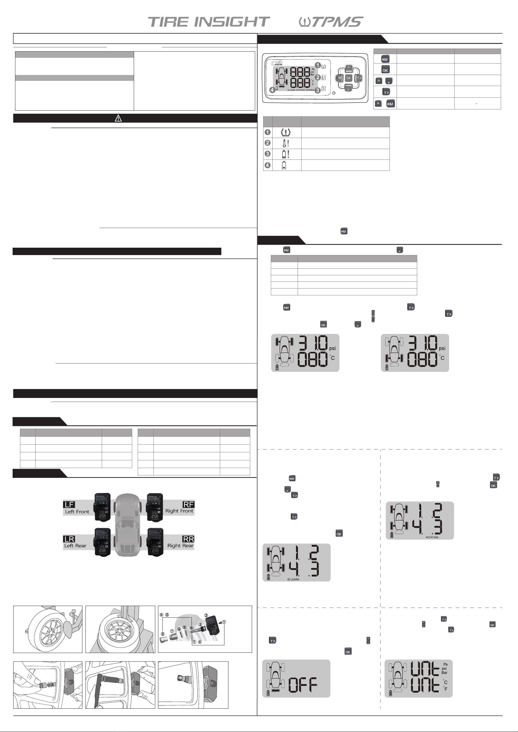
2.1 安裝輪胎位置
胎壓感知器在出廠前已完成配對,第一次安裝時,必須確認四組胎壓感知器上的號碼及對應安裝的
輪胎位置,才能上路使用。
2.2 安裝流程
(圖1) 鬆開輪胎。固定輪胎兩側並壓下,使其隆起。
(圖2) 拆卸輪胎。氣門嘴面對安裝手臂在一點鐘方向,進行拆卸。
(圖3) 感知器組裝,及安裝至輪胎之位置順序。
(圖4) 安裝感知器與氣門嘴。讓氣門嘴從輪圈孔穿過,調整感知器角度貼合輪圈內緣,以2 Nm鎖緊
感知器螺絲。接續裝上墊圈及氣門嘴螺帽,用手鎖緊氣門嘴螺帽。
(圖5/ 圖6) 使用扭力扳手以4 Nm鎖緊螺帽,再將帽蓋鎖緊。
注意:安裝過程請小心處理,避免安裝手臂碰撞感知器,造成感知器損毀。
系統警告
當系統出現警告燈號及"嗶"警告音,應立即減速並在安全停靠位置下檢查輪胎狀況,並立即至就近
合格輪胎維護廠進行相關修復及深入檢查。
產品警告
1.請不要在駕駛時操作胎壓監測接收器,不專心駕駛可能會導致受傷或死亡等嚴重後果,您將承擔此
全部風險和責任!
2.本系統為無線傳輸訊號,在某些特殊環境下,系統可能會因為干擾錯誤操作方法或安裝方法錯誤,
導致訊號減弱或收不到訊號狀況發生。車輛所黏貼之隔熱貼紙若含金屬成份,將有可能影響接收狀
況若胎壓監測接收器上的輪胎壓力與溫度會顯示為---,此狀況表示接收器收不到感知器所發射
的訊號,此時請將車輛遠離目前位置(附近可能有其他訊號干擾 ),或將車輛駛至附近的輪胎行進行
檢查亦或將胎壓監測接收器送回經銷商進行檢修。若是輪胎內的胎壓感知器的電池電量不足(電池可
能因異常狀況持續發生,使胎壓感知器持續發射訊號以警告駕駛者,導致電池壽命比正常使用年
限短)請儘速前往指定安裝據點檢查確認胎壓感知器是否需更換。
3.若接收器或感知器的電池沒電,請務必更換電池或感知器,否則若因此造成胎壓監測系統無法正常
運作及告警,您必須自行承擔所有的風險及責任。
4.若因為使用任何胎劑,對感知器的運作產生不利影響。本產品製造商不承擔任何責任。
系統安裝
無線胎壓監測系統需要有正確 的安裝方法,並由合格安裝人員依照手冊所指示的步驟進行安裝,系統
才能正確作動並享有相關保固。若因安裝不當或拆卸過程使感知器損壞,將無法予以保固。
注意:建議每年定期檢查"感知器氣門嘴",若出現損壞應立即更換以避免漏氣現象發生。
重要安全指南
1.產品配件清單
2.胎壓感知器安裝
3. 胎壓監測接收器說明
功能按鍵 一般模式 設定模式
背光及進入功能設定
(按住3秒後進入功能設定) 離開功能設定模式
告警聲靜音 儲存設定
進入背景恆亮
上下選擇/數值增減
切換胎壓/胎溫顯示 功能選擇/右鍵
+
3.1 主機面板按鍵功能介紹
VS-63W008 目錄
3.2 警示燈號介紹
異常警示說明
當感知器傳送異常訊號至接收器時,接收
器上的警示符號會閃爍,亦同時發出"嗶"
警告聲,並顯示出現異常的輪胎位置。
3.3 安裝位置建議
建議安裝於儀表板正中央1/3區域內或經測試為接收狀況最佳之位置。
SETTINGS :設定前後輪胎壓與胎溫 (註4.1)
ROTATION :輪胎順序調換 (註4.3)
LEARNING:感知器ID學習 (註4.2)
備胎模式:備胎啟用 (註4.4)
單位設定模式:胎壓胎溫單位設定 (註4.5)
< 前輪胎壓設定 < 後輪胎壓設定
4.設定功能選項
將 長按3~5秒後,進入設定畫面,按 鍵,依續出現以下幾種功能選項:
4.1 胎壓標準值/ 胎溫最大值設定
長按 鍵3~5秒,進入"SETTINGS"畫面。按 一次進入“胎壓胎溫設定"畫面後,可自行設定前輪與
後輪的胎壓標準值與胎溫最高值。按 鍵後先進行胎壓標準值設定,前輪數值閃爍,按 鍵選擇數
值大小,按 鍵前輪數值不閃爍即完成前輪胎壓值設定。接下來後輪的數值閃爍,按 鍵選擇數值
大小,按 鍵後輪數值不閃爍後,即完成四輪胎壓值設定。隨後進入胎溫值設定,設定方式如同胎
壓值。
注意:胎壓標準值,請參考車廠貼附在駕駛座車門之標語。
& 胎壓過低警示代表輪胎壓力已經洩漏至使用者所設定的胎壓標準值20%以下,或≦150kPa (22psi)。
& 胎壓過高警示代表輪胎壓力已經上升至使用者所設定的胎壓標準值50%以上。
& 胎溫過高警示代表輪胎溫度已經高於使用者所設定的胎溫最高值以上。
※ 如出廠值設定胎壓標準值為31psi,當胎壓≦24.8psi 或胎壓≧46.5psi會產生告警。
※ 如出廠值設定胎溫最高值為80℃,當胎溫≧80℃,會產生告警。
※ 氣候過熱或過冷造成胎壓不正常時,請至保養廠調整輪胎胎壓至標準值,以免胎壓監測接收器產生
誤判。
注意:
(1).電池型號:乾電池建議使用型號:勁量鹼性E91,1.5V,3號AA電池,一般鹼性電池工作溫度為
-
18℃
~
55℃
,高溫會導致漏液。
(2).節電設計:為了節省胎壓監測接收器的乾電池電力消耗,接收器有休眠設計,以達到節省電
池電力消耗,當車子啟動時,接收器即會自動再啟動。
(3).在設定模式的任一模式下,設定完成後若要回到胎壓胎溫顯示畫面,長按 鍵約3秒後,
即可回到胎壓胎溫顯示畫面。
4.2 ID學習設定
當第二次安裝或更換感知器時,接收器必須學習
新感知器ID。設定步驟如下:
注意:
(1).以洩壓方式學
習感知器ID時,若
洩壓速度不夠快速
可能會出現ID無法
學習成功的狀況。
< ID 學習設定畫面
1.長按 鍵3~5秒,進入 "SETTINGS" 模式。
2.按 鍵,直到進入 "LEARNING" 模式。
3.按 鍵,數字閃爍。
4.按住氣門嘴進行洩壓,接收器收到訊號,並發
出"嗶"聲,數字停止閃爍即學習完成。
5.再按 鍵,學習下一輪。
6.重複上述動作,全部學習完成,按 鍵儲存設定。
4.3 輪胎順序調換設定
< 調胎設定畫面
當輪胎進行調胎時,感知器位置會與原先設定
位置不同,必須進行順序調整,讓接收器顯示
正確輪胎位置,須進入"ROTATION"模式進行設
定。
在"ROTATION"模式下,螢幕上會顯示1~4數字,
按 鍵後,數字出現閃爍按 鍵可更改輪胎初
始順序,設定完成後,按 鍵即可儲存設定。
< 備胎模式設定畫面
4.4 備胎模式設定
車輛備胎如有需要安裝胎壓感知器時,讓接收器
顯示備胎的壓力與溫度,可在"備胎"模式進行
設定。
進入設定畫面會顯示備胎位置,按 鍵,字幕
出現閃爍,即可開始設定。按 鍵選擇ON 或
OFF,確認是否需要開啟備胎顯示模式,設定完
成後,按 鍵儲存設定。
< 胎壓單位設定畫面
4.5 胎壓胎溫單位設定
胎壓與胎溫有多種單位顯示,可於顯示單位
模式進行設定。進入Unit設定畫面後,按
鍵,進入胎壓單位,單位字幕閃爍,以 鍵
選擇單位,設定後,再按 鍵,進入胎溫
單位,設定方式與胎壓單位相同,設定完成
後,按下 鍵儲存設定。
請注意:4氣門嘴從孔洞插過,故1/3於輪圈內,2/3於輪圈外。
~於胎內。
1.感知器螺絲
2.感知器
3.橡膠墊圈
4.氣門嘴
5.塑膠墊圈
6.金屬墊圈
7.氣門嘴螺帽
8.帽蓋
於胎外。
~
燈號圖示編號 燈號訊息
胎壓過高 / 過低警示
胎溫過高警示
感知器電池電量過低警示,代表需要更換感知器
胎壓監測接收器電池電量不足,請更換電池
k
k
警告
FCC條例
NCC低功率電波輻射性電機管理辦法
產品警告
系統安裝
重要安全指南
1 產品配件清單
3.2警示燈號介紹
3.3安裝位置建議
2 胎壓感知器安裝
2.1安裝輪胎位置
2.2安裝流程
3 胎壓監測接受器說明
3.1主機面板按鍵功能介紹
4 設定功能選項
4.1胎壓單位設定
4.2音量大小設定
4.3胎壓標準值
胎溫最大值設定
4.4ID學習設定
4.5輪胎順序調換設定
FCC條例
此胎壓監測系統已遵守美國FCC法規第15條要求,但仍需注意以下兩點事項:
1.產品可能因其他有害的干擾,導致系統無法作動。
2.不正常的操作可能導致系統失敗。
注意:任何自行修改或變更此系統或硬體,將無法保證使用者的權益繼續受到保護。
SETTINGSSETTINGS
SETTINGS
NO Part Name Q’ty
5
6
7
2
1
1
1
8
1
9
Valve screw
AA battery
Quick installation guide
Product warranty card
Velcro
NO Part Name Q’ty
1
2
3
3
1
1
4
4
Sensor
Valve package (valve and screw)
Tire pressure monitoring receiver
Valve
VS-63W008 Contents
FCC Regulations
This tire pressure monitoring system has complied with Article 15 of the FCC regulatory requirements of the USA,
but it is still needed to pay attention to the following two items:
(1) Other harmful interferences may affect the system’s normal operation.
(2) Abnormal operation may cause the system to fail.
This equipment has been tested and found to comply with the limits for a Class B digital device, pursuant to part
15 of the FCC rules. These limits are designed to provide reasonable protection against harmful interference in a
residential installation. This equipment generates, uses and can radiate radio frequency energy and, if not installed
and used in accordance with the instructions, may cause harmful interference to radio communications. However,
there is no guarantee that interference will not occur in a particular installation. If this equipment does cause
harmful interference to radio or television reception, which can be determined by turning the equipment off and on,
the user is encouraged to try to correct the interference by one or more of the following measures:
-Reorient or relocate the receiving antenna.
-Increase the separation between the equipment and receiver.
-Connect the equipment into an outlet on a circuit different from that to which the receiver is connected.
-Consult the dealer or an experienced radio/TV technician for help.
FCC RF Radiation Exposure Statement:
This equipment complies with FCC radiation exposure limits set forth for an uncontrolled environment. End
users must follow the specific operating instructions for satisfying RF exposure compliance. This transmitter must
not be co-located or operating in conjunction with any other antenna or transmitter.
Note: The product will not be guaranteed if user change or modify the hardware and system design.
Warning
Product Warning
1.Do not operate a TPMS receiver while driving. The company is exempt from all consequences because of
driver’s careless and improper operation.
2.The system adopts the wireless transmissi of signals. In some special circumstances, interference or erroneous
methods of operation or installation method errors may cause weaker signal or its inability to receive signals. If
the insulation adhesive sticker of the windshield contains metal material, it will be likely to affect reception
conditions. If the tire pressure and temperature readings on the TPMS receiver are displayed as ---, this
condition represents the receiver cannot receive signals emitted by the sensors. Drive the vehicle away from
the current location (nearby there may be signal interference) or drive the vehicle to a tire shop to check, or
return the TPMS receiver to distributor for repair. If the battery status of the TPMS sensors inside the tire is low
(because abnormal conditions continue to occur, the battery may make the TPMS sensors continuously emit
signals to warn the driver, so that battery life is shorter than the normal life), please go as soon as possible to
the specified service stations to confirm whether the TPMS Sensors need to be replaced.
3.Please change the Receiver’s dry battery or sensor while the Receiver’s dry battery power is low or Sensor Low
battery warning is alarm, or it may cause the TPMS thus cannot be operated and alarm normally. You will take
all risks and responsibilities for this!
4.Temporary resealing or re-inflation products containing internal sealants or propellants in any tire assembly may
adversely affect the operation of the sensor/transmitter. The product manufacturer does not assume any liability
as a result of these.
Important Safety Guide
System Warning
When the system displays a warning light and warning "beeps", you should immediately slow down, stop in a safe location and check the
tire condition, and immediately drive to the nearest qualified tire maintenance garage to repair and make related in-depth examination.
Function key Normal mode Setting mode
+
Backlighting and enter the function
setting mode (hold for 3 seconds) Leave function setting mode
Mute the warning audio Save the setting
Up and down selection/
value adjustment
Rotation display setting Unit setting or right button
Set the backlight to be always on/off
(Fig 1) Loosen the tire. Fix both sides of the tire and press, and make it bulge.
(Fig 2) Remove the tire. The valve faces the mounting arm in the one o’clock direction, remove the tire.
(Fig 3) Remove the sensor. Loosen the fixing screw, allow the sensor separate from the valve, and release the nut to take it apart from
the valve.
(Fig 4) Install the sensor and valve. Insert the valve through the rim hole, fix the screw to secure the valve and sensor by 2 Nm in torque,
attach the sensor body to the inner surface of the rim by adjusting the angle of the sensor body.
(Fig 5/6) Install valve to the rim hole. Guide the washer into the valve, and fix the nut by 4 Nm in torque, then tighten the cap.
Note: Mount the tire. Grip the rim edge, and the valve is opposite to the mounting arm, avoid hitting the sensor during arm operation.
2.2 Sensor Assembly Process
Please follow the label on the sensor, install the sensor into the rims accordingly, it could skip the “ID Learning” steps for each sensor!
2.1 Installation Location
1.Product Parts List
2.Sensor Installation
3.2 Warning Light Symbol
Abnormal Warning Illustration
When the TPMS sensor transmits abnormal
signal to the receiver, a warning symbol will
blink and “beep” as an audio alarm. The
abnormal value is shown on the corresponding
tire on the receiver.
It’s our recommendation to mount within 1/3 of the region right on the center of dashboard, or the position
which can receive the sensor signal well.
Note:
1.Recommended battery type: Alkaline E91, 1.5V, AA battery, The operating temperature of regular alkaline
battery is -18℃~55℃, higher temperatures will cause battery leakage.
2.Power saving design: in order to decrease the consumption of receiver battery, the receiver has a dormant
design, to save the battery power consumption. When the ignition is on, the receiver will be restarted
automatically by shock.
3.If you finish setting and want to return back to tire pressure/tire temperature display screen under any
setting mode, please hold the button for about 3 seconds
3.3 Recommend the Receiver Mounting Position
4.Setting Items
3.1 Buttons Function Introduction
3.Installation of Tire Pressure Monitoring Receiver
Note: For the standard tire pressure value, please refer to the placard which be attached to the side of the driver seat.
●Warning of excessive low tire pressure indicates tire pressure has been leaked to 20% or less of the standard tire pressure value
set by the user, or ≦150 kPa (22psi).
●Warning of excessive high tire pressure indicates tire pressure has been risen to 50% or more of the standard tire pressure value
set by the user.
●Warning of excessive high tire temperature indicates tire air temperature is higher than the user setting value of the warning tire air
temperature.
●For example, if the standard tire pressure value is 31 psi, when tire pressure is increased ≧46.5psi or decreased ≦24.8psi, the
receiver will alarm.
●For example, if the warning temperature is 80℃, when tire temperature is increased ≧80℃, the receiver will alarm.
●If the environment temperature is too hot or cold, the tire pressure will vary accordingly. Please go to the tire shop to inflate or deflate
the tires to prevent an erroneous alarm.
Hold for 3~5 seconds to enter the “SETTINGS”mode. Press and set the standard tire pressure value,
the value of the front wheel will blink, press the button to adjust the value. Press one more time to switch
to front wheel temperature setting, press the button to adjust the value. The value is fixed and will stop
blinking after pressing , then press for the rear wheel, and repeat the procedure.
4.1 Tire Pressure Standard and Temperature Warning Value Setting
▲ Rear wheel tire pressure and temperature value setting▲ Front wheel tire pressure and temperature value setting
4.2 ID LEARNING Setting
▲ ID LEARNING setting
Note:
1.When learning the sensor IDs by pressure deflation, please
proceed with fast deflation to avoid unsuccessful ID learning.
4.3 Tire Position Rotation Setting
4.4 Spare Tire Setting
▲ Rear wheel tire pressure and temperature setting
4.5 Tire pressure and tire temperature unit setting
▲ Tire pressure and temperature unit setting
Function Description
SETTINGS Tire pressure and temperature setting for front and rear tire (4.1)
LEARNING TPMS sensor ID learning (4.2)
ROTATION Tire position rotation (4.3)
SPARE TIRE Spare tire off or on (4.4)
Unit Tire pressure and tire temperature unit setting (4.5)
System Installation
The wireless TPMS needs to be installed by qualified personnel in accordance with installation manual to enjoy related warranty. If improper
assemble or disassemble process damages the sensor, it will not be covered by warranty.
Reminder: annual periodic inspection for the "sensor valve" is proposed, which should be replaced immediately if damaged, in order to avoid
air leakage.
k
k
When the wheel is switched, the sensor position would be different
from original. You should use RORATION mode for tire position
setting.
In ROTATION mode, 1 to 4 digits is showed on screen. Press ,
then the digit will flash. Press to adjust tire position. Press to
save when the setting is completed.
Enter “Unit” setting mode, press once for tire pressure unit, the
unit will blink, press to choose the desired unit, press to
complete the unit setting. Then press for temperature unit, follow
the previous procedure to complete the setting.
If it is necessary for the spare tire to install a TPMS sensor, the
receiver could display the spare tire pressure and temperature, it
can be set in the SPARE TIRE mode.
It shows the spare tire position when using the Spare Tire setting.
Tap button and the digit would be flashing. Tap button to
select ON or OFF and confirm whether you need to activate spare
tire display mode. After setting is completed, tap button to save
the setting.
~Outside of the rim 1.Screw
2.Sensor
3.Rubber washer
4.Valve core
5.Washer
6.Washer
7.Nut
8.Valve cap
~Inside of the rim
Fig 1 Fig 2 Fig 3
Fig 4 Fig 5 Fig 6
Light SymbolNo. Abnormal Light Message
Alarm for excessive high tire temperature
Warning for low battery in TPMS sensor,
need to replace new sensor
Warning for low battery in receiver,
need to replace new battery
Alarm for excessive high/low tire pressure
▲
ROTATION setting
Hold for 3~5 seconds to enter the setting mode, press for the following functions:
When replacing or installing a tire pressure monitoring sensor for
a second time, the receiver must learn the new tire pressure
sensor ID. The setting procedure is below:
4.2.1 Hold the button for 3 to 5 seconds, enter the
“SETTINGS” mode.
4.2.2 Press twice to enter the “LEARNING” mode.
4.2.3 Press the button, the digits will blink.
4.2.4 Deflate the tire, the receiver will beep when receiving the
signal; the ID learn setting is finished when the digits stops
blinking.
4.2.5 Press the button again, then do the learning procedure
for the next tire.
4.2.6 Repeat the above procedures until completing the learning
of the 4 tires, then please press the button to save the
ID numbers.
Quick Installation Guide
Battery TPMS System
FCC Regulations
FCC RF Radiation Exposure Statement
Product Warning
System Installation
Important Safety Guide
1.Product Parts List
2.Sensor Installation
2.2 Sensor Assembly Process
2.1 Installation Location
3.Installation of Tire Pressure Monitoring Receiver
4.Setting Items
4.1 Tire Pressure Standard and Temperature Warning
Value Setting
4.2 ID LEARNING Setting
4.3 Tire Position Rotation Setting
4.4 Spare Tire Setting
4.5 Tire pressure and tire temperature unit setting
3.3 Recommend the Receiver Mounting Position
3.2 Warning Light Symbol
3.1 Buttons Function Introduction
SETTINGS
SETTINGS
SETTINGS


