TQC AB3120 User manual
1
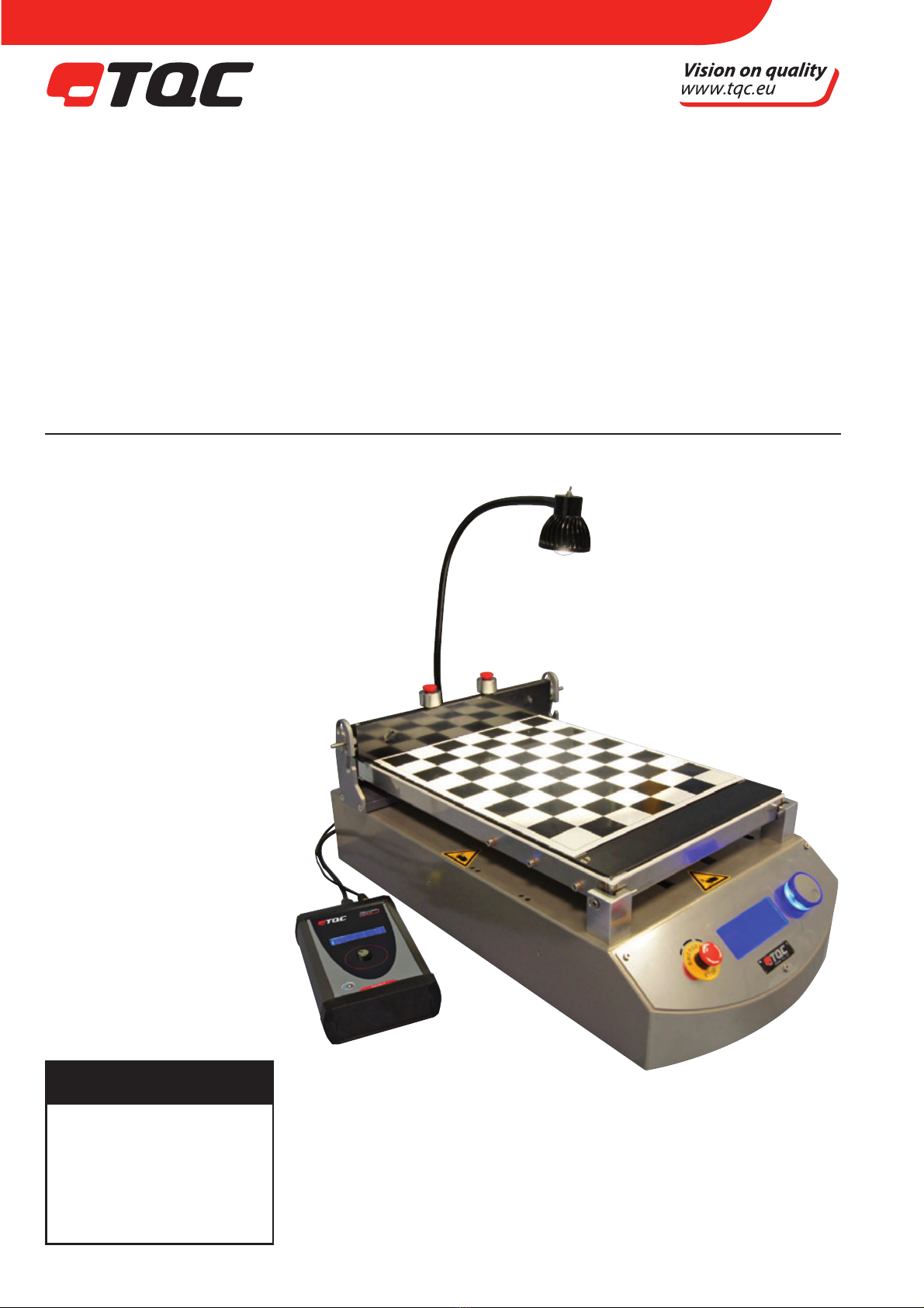
TQC AUTOMATIC FILM APPLICATOR
INCL. OPTIONAL TOOLS
AB3120, AB3220, AB3320, AB3400, AB3420, AB3425, AB3125, AB3225,
AB3325, AB3405, AB3075, AB3090
User Guide
V3.5 0417
IMPORTANT!
Before taking this
instrument in use we
strongly advise you
to read this manual
carefully.

2
CONTENT
1 GENERAL 4
1.1 Importance of operating manual 4
1.2 User-responsibility 4
1.3 Responsibility of personnel 4
1.4 Dangers 4
1.5 Designated purpose 4
1.6 Copyright 5
1.7 Manufacturer’s/Supplier’s address 5
2 SAFETY INSTRUCTIONS 5
2.1 Meaning of Symbols 5
2.2 Availability of Safety Information 5
2.3 Training of Personnel 6
2.4 Dangers from Electrical Energy 6
2.5 Points of Special Danger - Moving Zone tool carrier 6
2.6 Points of Special Danger - Heated Film applicator 6
2.6 Care, Maintenance, Repairs 7
2.7 Modications to the Equipment 7
2.8 Cleaning of the Instrument and Disposal of Materials 7
3 TRANSPORT AND STORAGE 7
3.1 Packing 7
3.2 User: Check on Receipt 7
3.3 Reporting Transport Damage and Documentation 8
3.4 Storage and Protective Measures when not in use 8
4 INSTRUMENT DATA 8
4.1 Name / Article 8
4.2 Scope of Supply 9
4.3 Technical Data 9
4.4 Dimensions and Weight 10
4.5 Basic Unit 10
4.6 Noise Level 10
5 INSTALLATION AND ASSEMBLY 11
5.1 Installation and Operation 11
5.2 Preparation of Energy Connections 11
5.3 Vacuum 11
5.4 Mains Connection 11
EN

3
6 INSTRUMENT CONTROLS AND FUNCTIONS 12
6.1 Overview 12
7 INSTRUMENT COMPONENT ASSEMBLY 13
7.1 Overview 13
7.2 Instrument Preparations 14
7.3 Glass Bed 14
7.4 Perforated Vacuum Bed 14
7.5 Double Channel Vacuum Bed 14
7.6 Film Applicators (Tools) 15
7.7 Test Charts 15
7.8 Drying Time Recorder 16
7.9 Multi Tool Platform 16
8 MENU DISPLAY INFORMATION AND OPERATION 16
8.1 Automatic Film applicator operation 16
8.2 Drying Time recorder operation 18
8.3 Heated Film bed control 20
8.4 Warning signals 20
9 OPERATION 20
9.1 Preparatory Work 20
9.2 Film Application 20
9.3 Start the instrument 21
10 CARE AND MAINTENANCE 21
10.1 Inspection and Maintenance 21
10.2 Disposal of Materials 21
10.3 Customer Service 21
11 DISCLAIMER 22
ANNEX A | INSTALLATION OF THE VACUUM BED 23
ANNEX B | POSITIONING OF SPIRAL BAR LIFTER 24
ANNEX C | INSTALLATION OF THE LAMP 25
ANNEX D | POWER SUPPLY HEATED MODELS 26
ANNEX E1| TEST CHART PLACEMENT - NON-HEATED-MODELS 30
ANNEX E2 | TEST CHART PLACEMENT - HEATED MODELS 34
ANNEX F | GRINDOMETER TOOL FOR AFA 39
ANNEX G | TQC HARDNESS PEN HOLDER FOR AFA 48
EN

4
1 GENERAL
1.1 Importance of operating manual
This manual is written in order to become familiar with all the functions and possible applications
of the instrument. It contains important instructions about how to use the instrument safely
and economically; according to the purpose designated. Following these instructions is not only
essential to avoid risks. It also reduces repair costs and down-time and increases the products
reliability and service-life.
Anyone who works with the instrument should follow the instructions in this manual, particu-
larly the safety related instructions. Additionally local rules and regulations relating to environ-
mental safety and accident prevention should be observed.
1.2 User-responsibility
The user should
a) Only allow persons to work with the instrument who are familiar with the general instructions
on how to work safely and to prevent accidents. The use of the instrument should have been
instructed duly. The safety chapter and the warnings in this manual should have been read
and understood; acknowledged as evidenced by their signature.
b) Regularly check the safety-awareness of personnel at work.
1.3 Responsibility of personnel
Before commencing work anyone appointed to work with the instrument should pay attention
to the general regulations relating to working safety and accident prevention. The safety chapter
and the warnings in this manual should have been read and understood; acknowledged as
evidenced by their signature.
1.4 Dangers
This instrument has been designed and constructed in accordance with state-of-the-art techno-
logy and the acknowledged safety regulations. Nevertheless, working with the instrument may
cause danger to the life and health of the operator or to others, or damage to the instrument or
other property. Therefore the instrument should only be used for its designated purpose, and in
a perfect technical condition. Any defect that could have a negative eect on safety should be
repaired immediately.
1.5 Designated purpose
The TQC Film applicator is exclusively designed to apply lms of paint and coatings on test panels
and test charts and as from models launched after Apr. 2013 for testing of the drying time of
coatings on previous described substrates.
Other applications constitute improper use. TQC will not be held liable for damage resulting
from improper use.
EN
5
Danger
Warning
Designated purpose also includes properly observing all instructions in the operation manual,
and adherence to inspection and maintenance schedules.
1.6 Copyright
The copyright of this operating manual remains with TQC.
This operating manual is intended solely for the user and his personnel. Its instructions and
guidelines may not be duplicated, circulated or otherwise passed on to others, neither fully, nor
partly. Infringement of these restrictions may lead to legal action may be taken if this restrictions
are infringed upon.
1.7 Manufacturer’s/Supplier’s address
TQC The Netherlands,
Molenbaan 19 T +31(0)10-7900100,
2908 LL Capelle aan den IJssel F +31 (0)10-7900129
2 SAFETY INSTRUCTIONS
2.1 Meaning of Symbols
The following symbols for dangers are used in this instruction manual.
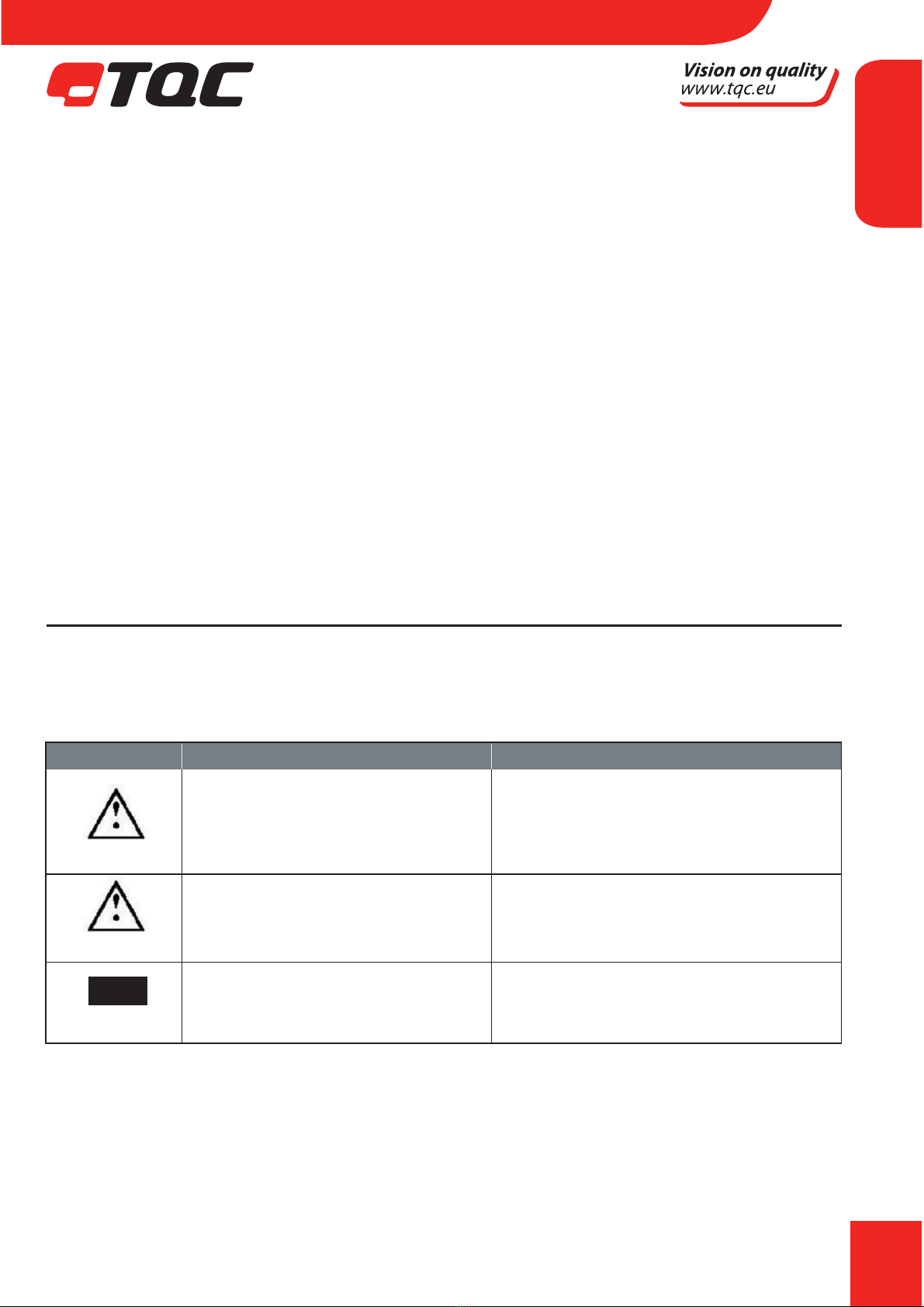
Symbol Explanation Warning
Possible immediate danger to If this guideline is not noted it can
the life or health of personnel lead to severe danger to health,
up to fatal injury
A dangerous situation could Non observance of this guideline
be caused can lead to injury or to
damage to equipment.
NOTE Special tips and particular Guidelines to make optimal use of
information the instrument.
2.2 Availability of Safety Information
The instruction manual should be kept at the place where the instrument is operated.
In addition to the information contained in the instruction manual, general and local regulations
for accident prevention and environmental protection shall be kept available and observed.
EN

6
Always ensure all guidelines in respect of safety and dangers on the instrument are in readable
condition.
In case of danger the instrument has to be switched o by means of the emergency-button on
the front of the instrument. Then eliminate danger.
2.3 Training of Personnel
t "OZPOFXIPPQFSBUFTUIFJOTUSVNFOUTIPVMECFUSBJOFEQSPQFSMZ
t *UIBTUPCFDMFBSXIPIBTXIJDISFTQPOTJCJMJUZSFHBSEJOHDPNNJTTJPOJOHTFUVQPG
maintenance and repairs, installation, and operation.
t "OZPOFXIPIBTOUöOJTIFEUSBJOJOHTIPVMECFTVQFSWJTFECZBOFYQFSJFODFEQFSTPOXIJMF
working with the instrument.
2.4 Dangers from Electrical Energy
t 8PSLPOUIFFMFDUSJDBMTVQQMZNBZPOMZCFEPOFCZBRVBMJöFEFMFDUSJDJBO
t 5IFFMFDUSJDBMFRVJQNFOUPGUIFJOTUSVNFOUNVTUCFDIFDLFESFHVMBSMZ-PPTFDPOOFDUJPOTBOE
cable damaged by heat must be corrected immediately.
t "MXBZTNBLFTVSFUIFJOTUSVNFOUTQPXFSJTUVSOFEPòXIJMFBEKVTUJOHBOZFMFDUSJDBM
component.
2.5 Points of Special Danger - Moving Zone tool carrier
There is one special point of danger in the moving zone of the tool carriers:
Do not move the Applicators Tool Carrier Bar on the instrument manually!
Keep your hands away from the work area and tool carrier bar after the
instrument has started!
2.6 Points of special danger - Heated Film applicators
The TQC AB3400 and AB3405 are both heated lm applicators and are able to reach temperatu-
res above 60 °C.
Contacting the heated lm applicator may cause injuries. Handle the hot surface
with care.
Don’t leave the heated vacuum bed unattended for extended periods.
Danger
Danger
Warning
EN

7
2.7 Care, Maintenance, Repairs
t "MXBZTNBLFTVSFUIFJOTUSVNFOUJTDPOOFDUFEUPBOFBSUIFETPDLFU
t .BJOUFOBODFBOEJOTQFDUJPOTIPVMECFDBSSJFEPVUBUUIFDPSSFDUJOUFSWBMT
t 0QFSBUJOHQFSTPOOFMTIPVMECFJOGPSNFECFGPSFTUBSUJOHXJUINBJOUFOBODFPSSFQBJSXPSL
t "MXBZTNBLFTVSFUIFJOTUSVNFOUTQPXFSJTUVSOFEPòBOEUIFJOTUSVNFOUJTOPUDPOOFDUFEUP
a socket while adjusting any electrical component whenever maintenance, inspection or repair
work is done.
t %POPUPQFOUIFJOTUSVNFOU*ODBTFPGNBMGVODUJPOBMXBZTDPOTVMUUIFNBOVGBDUVSFS
t /FWFSUPVDIFMFDUSPOJDTPSDJSDVJUCPBSETXIFOOPU&4%TFDVSFE
2.8 Modications to the Equipment
t "OZNPEJöDBUJPOTPSBEEJUJPOTPSBMUFSBUJPOTUPUIFJOTUSVNFOUNBZTPMFMZCFNBEFXJUI
permission from the manufacturer.
t "MMNFBTVSFTJOWPMWJOHNPEJöDBUJPOTSFRVJSFXSJUUFODPOöSNBUJPOPGBQQSPWBMGSPN52$
t *OTUSVNFOUTXIJDIBSFOPUJOGBVMUGSFFDPOEJUJPONVTUJNNFEJBUFMZCFTXJUDIFEPò
t 0OMZVTFSFQMBDFNFOUQBSUTGSPNUIFPSJHJOBMTVQQMJFS1BSUTVTFEGSPNPUIFSTPVSDFTBSFOU
guaranteed to take the loading and meet the safety requirements.
2.9 Cleaning of the Instrument and Disposal of Materials
t 8IFOJOVTFJUJTOPUBMXBZTQPTTJCMFUPBWPJETPNFTQJMMPGQBJOUPOUIFXPSLTVSGBDF
t 5SZUPLFFQUIFJOTUSVNFOUBTDMFBOBTQPTTJCMFUPQSFWFOUEJTUPSUJPOTPGGVODUJPOT
t 5PDMFBOUIFJOTUSVNFOUQSPQFSMZVTFBTVJUBCMFTPMWFOUUPEJTQPTFSFNBJOTPGQBJOUPSJOL
t 8FBSHMPWFTEVSJOHDMFBOJOH%POUTQJMMBOPWFSEPTFPGTPMWFOUEVSJOHDMFBOJOH
t $MFBOJOHNBUFSJBMTNVTUBMXBZTCFVTFEBOEEJTQPTFEPGDPSSFDUMZ
3 TRANSPORT AND STORAGE
3.1 Packing
Please take note of pictorial symbols on the packing.
3.2 User: Check on Receipt
Check packing for damage
After unpacking check complete supply.
EN
8
3.3 Reporting Transport Damage and Documentation
Any damage should be documented as accurately as possible (possibly photographed) and
reported to the relevant insurers or, in the case of sales “delivered to customers works”, to the
supplier.
3.4 Storage and Protective Measures when not in use
The instrument must be stored in a dry (± 40%rH) place at a temperature between 10 - 40°C.
The storage period should not be longer than 3 months.
Store instrument in the original packing if possible.
4 INSTRUMENT DATA
4.1 Name / Article
AB3120 TQC motorised automatic lm applicator 230V with
glass bed (A) and combined attachment assembly for
standard block applicators and wire bar coaters.
AB3125 TQC motorised automatic lm applicator 110V with
glass bed (A) and combined attachment assembly for
standard block applicators and wire bar coaters.
AB3220 TQC motorised automatic lm applicator 230V with
perforated vacuum bed (B), built-in vacuum pump
and combined attachment assembly for standard
block applicators and wire bar coaters.
AB3225 TQC motorised automatic lm applicator 110V with
perforated vacuum bed (B), built-in vacuum pump
and combined attachment assembly for standard
block applicators and wire bar coaters.
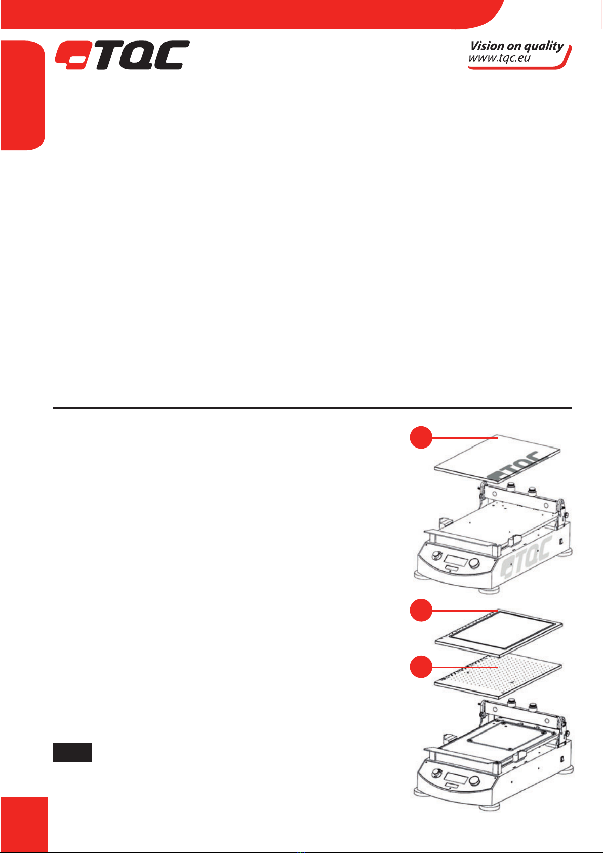
NOTE TQC Automated Film Applicators equipped with a
perforated vacuum bed can be retrotted with an
optional double channeled vacuum bed and vice
versa.
A
C
B
EN

9
AB3320 TQC motorised automatic lm applicator 230V with
double channelled vacuum bed (C), built-in vacuum
pump and combined attachment assembly for
standard block applicators and wire bar coaters.
AB3325 TQC motorised automatic lm applicator 110V with
double channelled vacuum bed (C), built-in vacuum
pump and combined attachment assembly for
standard block applicators and wire bar coaters.
NOTE TQC Automated Film Applicators equipped with a double channelled vacuum bed can
be retrotted with an optional perforated vacuum bed and vice versa.
AB3400 TQC motorised automatic lm applicator 230V with heated perforated vacuum bed,
built-in vacuum pump and combined attachment assembly for standard
block applicators and wire bar coaters.
AB3405 TQC motorised automatic lm applicator 110V with heated perforated vacuum bed,
built-in vacuum pump and combined attachment assembly for standard
block applicators and wire bar coaters. Includes 110 VAC to 230 VAC converter
AB3420 TQC motorized automatic lm applicator 230 VAC
(exclusive application bed) inclusive vacuum pump + automatic clamp unit.
AB3425 TQC motorized automatic lm applicator 110 VAC
(exclusive application bed) inclusive vacuum pump + automatic clamp unit.
NOTE Include one or more application beds form the Accessories (Optional) section
below to complete the TQC motorized automatic lm applicator.
Accessories (Optional)
AB3500 TQC Drying time recorder tool
(Only suitable for models with rmware version 2.01 or above)
AB3000 Rubber mat for TQC Automated Film Applicator.
AB3100 Replacement Glass Bed for TQC Automated Film Applicator
AB3200 Replacement perforated vacuum bed for TQC Automatic Film Applicator
(Not for heated model).
AB3300 Replacement double channelled vacuum bed for TQC Automated Film Applicator.
VF0135 Spiral bar adapters / lengthening rods
AB3416 110 VAC to 230 VAC converter
AB3075 Grindometer tool for AFA
4.2 Scope of Supply
The scope of supply varies due to the specic applications previously mentioned in the purchase
order. (I.e. Glass Bed Perforated Vacuum Bed, Double Channel Vacuum Bed and accessories.)
EN

10
4.3 Technical Data
Automatic Film Applicator
Traverse Speed : 2 – 500 mm/s
Traverse Speed accuracy : +/- 1% of set speed
Stroke length : 50 – 359 mm
Stroke length accuracy : +/- 2 mm
Max test chart size : DIN A3
Max test substrate thickness : 35mm including applied coating
Max. test panel size (only glass bed models) : 460 x 300 x 9 mm ( LxWxH)
Max. Width alternative lm applicators : max. 300 mm
Max. Height alternative lm applicators : max. 80 mm
Wire bar length : max. 325 mm spiral area in 364 mm length at
xation points
Wire bar diameter : max. Ø10 mm at the xation points
Max vacuum : -178 mbar
Drying Time Recorder
Drying time range : 1 min. – 2880 min (48 hours)
Time accuracy : ≤ 1% of set time
Maximum test length : 350mm
Maximum number of tracks : 8
Force per needle : 3,5g / 0,03N
Weight separate weights : 5g / piece
Ø needle : 2 mm
Material : aluminium, stainless steel
Dimensions : 50x60x 315 mm / 1.97x2.36x315x12.4 inch
Weight : 280g
Heated perforated vacuum bed
Minimum temperature : Ambient + 5ºC
Maximum temperature : Ambient + 100ºC (Absolute max 140ºC)
Resolution of set temperature : 1ºC
Resolution of readout temperature : 0.1ºC
Temperature controller : Separate
Power consumption heating : 450 Watt
Power Supply : 230V, 50Hz
4.4 Dimensions and Weight
D x W X H : 650 x 350 x 240 mm
Net weight : 31 kg – 36 kg dependent on model
EN
11
Danger
4.5 Basic Unit
Power Supply : 115 – 230 V, 50 - 60 Hz
Power consumption : max. 80 Watt
Display : Blue Illuminated, graphic 100 x 35 mm, 193x64 pixels
Safety : Emergency Button and intelligent proximity
switches, integrated Acoustic Alarm
Function : Jog Shuttle knob by Rotation / Pushing
Drawn down Speeds : 12 steps selectable from 2 - 500 mm/s. and free selectable (custom)
Drawn down Lengths : A5 / A4 / A3 and free selectable (custom with variable starting/
stopping point), except for the heated vacuum bed which only
operates with A3. If smaller test charts are used a A3 sized paper
frame
has to be created to protect the holes from paint walk.
4.6 Noise Level
The continuous noise level from the instrument does not exceed 70 dB.
5 INSTALLATION AND ASSEMBLY
5.1 Installation and Operation
The instrument has to be installed in a suitable place, preferably on a sturdy table or work area,
with normal ambient temperature. Special xings are not required.
Carefully unpack the apparatus and the accessories and check complete supply.
Place, if necessary, a spirit level on the work surface and adjust the height of the feet.
5.2 Preparation of Energy Connections
The instrument is equipped with a safety tested mains supply cable and may only be connected
to plug sockets with earth connection complying with the safety regulations.
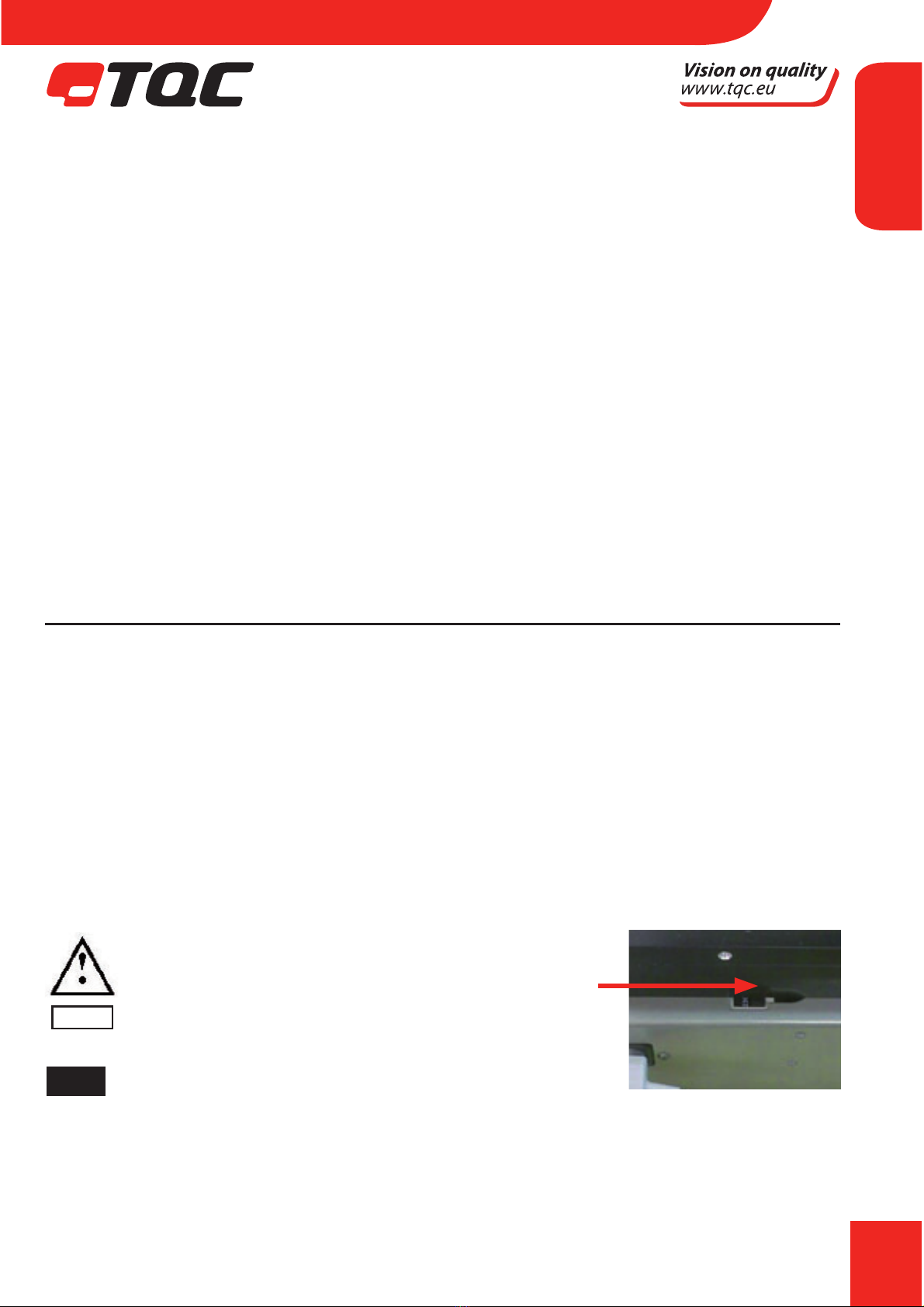
Before connecting the instrument, check whether
the supply voltage specied on the indication label
corresponds to the local supply voltage. If it does not,
the instrument must not be connected under any
circumstances. Contact your local supplier or TQC for
full specications on how to set the correct voltage.
NOTE Voltage selector might be hidden, depending on model.
5.3 Vacuum Connection
Only applicable for selected applicator series. The applicator has a built in vacuum pump to
provide the vacuum bed enough under pressure to hold test charts of either A4 or A3 size. When
the size diers from the stated A4 or A3, cover up all remaining holes to the nearest larger size in
EN

12
order to create adequate vacuum. The level of vacuum created may
dependon operation and age of the machine as well as test substrate used.
5.4 Mains Connection
The mains connection is located at the rear of the instrument. Plug in the female plug in the
socket on the rear of the housing. The ON/OFF Switch is located at the right hand site near the
end of the instrument.
NOTE When installing AB3400 and AB3405, please see Annex D for installation
6 INSTRUMENT CONTROLS AND FUNCTIONS
6.1 Overview
1. Display with process information
2. Jog Shuttle
3. Emergency button
4. Acoustic alarm / Buzzer
5. Levelling supports
6. Glass bed or vacuum bed
7. Automated clamping device for test charts
8. Mains connection
9. Spiral applicator weight
10. Spiral bar release device
11. Hand protection device
12. Adjustable tool holder
13. Main Switch
3 4 1 52
9
7
12
8
13
6
10
11
EN
13
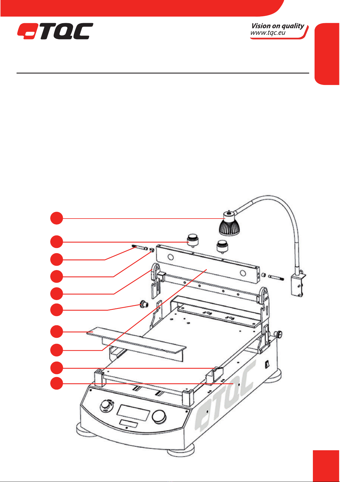
7 INSTRUMENT COMPONENT ASSEMBLY
7.1 Overview
1. Housing
2. Splash shield
3. Tool Carrier
4. Hight Adjustment xation
5. Spiral bar weight
6. Spiral bar weight guide pins
7. Spiral bar weight guide rings
8. Spiral bar weight extra weights
9. Lamp assembly
10. Lifter
9
8
6
7
3
4
2
1
5
10
EN

14
7.2 Instrument Preparations
Position glass bed or vacuum bed between the designated red supporting studs at the 4 corners
on the unit. The heated vacuum bed model comes with a pre assembled vacuum bed. For the
other vacuum models follow the vacuum seal installation instructions in Annex A.
7.3 Glass Bed
This bed 470 x 300 x 12 mm can either be used directly as an application carrier or (for example)
smaller cards or foils.
Charts or foils are automatically clamped in a special device at the end of the unit as soon a test is
performed. For cleaning purposes the glass bed can be removed.
7.4 Perforated Vacuum Bed
In order to create an adequate vacuum the instructions for setting up the vacuum seal O-rings
as in Annex A need to followed. The Perforated Vacuum Bed is automatically connected to the
vacuum pump as soon as placed between the red supporting studs on the O-rings.
The Perforated Vacuum Bed serves to hold thick foils, charts and other papers for coating.
The area size under vacuum depends on the selection made in the menu of the instrument
and on the model. (See 8.1 – RUN SETUP-LENGTH) See ANNEX E1 / E2 for more information on
Test Chart Placement.
7.5 Double Channel Vacuum Bed
In order to create an adequate vacuum the instructions for setting up the vacuum seal O-rings
as in Annex A need to be followed . Double Channel Vacuum Beds are used for testing on foils.
When otherwise the foil will not remain smooth on a normal vacuum bed. The Double Channel
Vacuum Bed only has vacuum in two concentrically rings on the outside of the bed. This requires
the foils to be about A3 size for the Double Channel Vacuum Bed to be able to hold them.
To prevent pollution of some holes outside the dimensions of charts we advise to cover the
surrounded area with paper or tape.
NOTE For assembly please also watch included DVD
EN
15
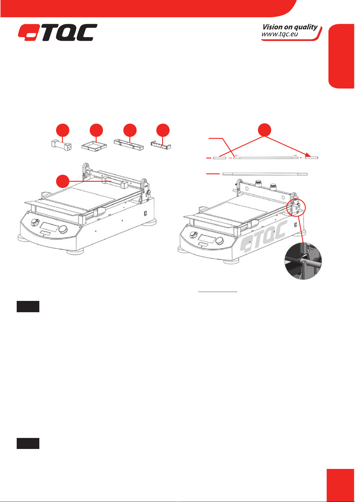
7.6 Film Applicators (Tools)
Spiral Bar applicators, Bird applicators, Baker applicators, Quadruplex applicators, SAG Quadru-
plex applicators Adjustable Micrometer applicators, SAG and levelling applicators. Place the
applicators as shown in below pictures;
For details on lm applicators datasheets are available on www.tqc.eu
NOTE The length of TQC Spiral bar coaters has changed during the years. The older shorter
version can be used on the TQC Automatic Film Applicator by the use of optional
available lengthening rods.
7.7 Test Charts
We supply a range of test charts (TQC, Leneta® or equivalent) like:
Opacity (hiding power) charts, Opacity Display charts, Sag and levelling charts, Brush out charts,
Plain White charts or others. CERTIFIED TQC TEST CHARTS!!!
For more details go to:
http://www.tqc.eu/en/products/productlistarticles/214/1/false/Test-charts
NOTE For details on Test Chart placement, please see Annex E
2 3 4 5
1
A
Total length 334 mm
Total length 440 mm
Detail A scale 2:3
Ø 8 mm
Ø 10 mm
Ø 10 mm
EN

16
7.8 Drying Time Recorder
The TQC Automated Film Applicator can be used as a Drying Time Recorder. In order to use the
TQC Automatic Film Applicator as a Drying Time Recorder following steps need to be followed:
t 3FNPWFUIF4QJSBMCBSXFJHIUGSPNESBXJOHDIBQUFSCZQVMMJOHPVUUIF4QJSBMCBSXFJHIU
guide pins(6).
t 5BLFDBSFUIBUCPUI4QJSBMCBSXFJHIUHVJEFQJOTBOE4QJSBMCBSXFJHIUHVJEFSJOHTBSF
stored in a safe place. In order to not to lose them.
t 1MBDFUIFPQUJPOBMBWBJMBCMF%SZJOH5JNF3FDPSEFS5PPMPOUIFCBSPGUIF52$"VUPNBUJD'JMN
Applicator as illustrated in below image:
8 MENU DISPLAY INFORMATION AND OPERATION
8.1 Automatic Film applicator operation
TQC Start screen after switched on.
Switch on instrument by mains switch at the right side on
the housing. This is the rst screen shown after switching
on the instrument.
NOTE The version number displayed is the rmware version number.
RUN - Automatically the rst selection screen or the
MAIN MENU appears
Press the Jog shuttle knob to start the sequence.
The applicator carrier bar is moved and set in position.
3A A
Detail Ascale 1:1
3B
B
Detail Bscale 1:1
Click
Automatic Film Applicator
V2.01
RUN
Press START to activate the
automatic lm applicator.
START
EN

17
RUN - Positioning Chart
The current draw down speed as well as the length is
shown in the top of the display. Press the Jog shuttle knob
to conrm or turn it to go back in the menu and make
changes. Place the draw down chart on the glass bed or
glass bed or vacuum bed. Choose the appropriate
applicator to full the test.
RUN – Applicator and Paint applying
Apply just enough paint to full the test on the test chart
chosen. Press the Jog shuttle knob to start the run or turn
it to go back in the menu and make changes. Display
shows“Running”. Keep your hands away from moving
parts.
MAIN MENU – Run, Run setup, Instrument setup
In the main menu you can change parameters according to
your needs. Rotate the Jog shuttle knob to select and press
to
choose. Follow the questions as they come.
RUN SETUP - Set Speed
Push the Jog shuttle knob to set the draw down speed.
RUN SET-SPEED
There are 12 preset speeds to choose from, 2 – 500 mm/s.
Custom is a free selectable speed in 1mm/s intervals.
After made changes rotate to BACK and press the Jog
shuttle knob.
RUN SETUP – Set Length
Push the Jog shuttle knob to set the traverse length.
RUN SETUP-LENGTH
There are 3 preset chart sizes selectable, A5 - A4 - A3
followed by an auto return of the tool carrier bar. Selecting
“Custom” oers you to set a Start and End point on the
platform. The traverse length is automatically set in
RUN
Place applicator and apply
print.
Stay clear from moving parts !
RUN BACK
50 mm/s A4
RUN
Place applicator and apply
print.
Stay clear from moving parts !
RUN BACK
50 mm/s A4
MAIN MENU
Run
Run setup
Instrument setup
Drying time recorder
RUN SETUP
Set speed
Set length
Set drying time recorder BACK
RUN SETUP-SPEED
Speed in mm/sec
BACK
[] 2 [ ] 5 [ ] 10
[] 20 [ ] 30 [√] 50
[] 70 [ ] 80 [ ] 100
[] 200 [ ] 300 [ ] 500
[] Custom [ 500 ]
RUN SETUP
Set speed
Set length
BACK
RUN SETUP-LENGTH
BACK
[] DIN A5
[√] DIN A4 [] DIN A3
[] Custom Start point [ 04.9]cm
End point [ 29.2]cm
Length 24.3 cm
[√] Auto return option
EN

18
accordance with the start/end points in millimetres.
After made changes rotate to BACK and press the Jog shuttle
knob VACUUM will only switch dependent on the length
of the test chart to A4 or A3, except for the heated vacuum
bed which only operates with A3. If smaller test charts are
used you have to create a A3 sized paper frame to protect
the holes from paint walk.
NOTE When using the custom length settings the spiral bar release studs can not be used
and need to be set to the end of the application bed, as close as possible to the display.
MAIN-MENU – Instrument setup
In the main menu rotate the jog shuttle knob to
Instrument setup and press on it.
INSTRUMENT SETUP
Select Language to set the desired language.
Select Units to set: Speed in mm/s, cm/s or inch/s and
Length in mm, cm or inches. Select Acoustic signals:
Signals o, Low volume or High Volume.
8.2 Drying Time recorder operation
The TQC drying time recorder is partially preset by the settings of the Automatic Film application.
In order to set up a new drying time test follow the steps below:
MAIN MENU – RUN SETUP
In the run setup menu the general setting of the Film
applicator and separate of the drying time recorder settings
can be entered. Select the “Set drying time recorder” menu
to get into the set-up menu for the drying time recorder.
RUN SETUP-DRYING TIME RECORDER
Within the Drying time recorder setup options as track time
total run time for drying time, alarm interval and vacuum
control can be set. Track time can be set from 1 minute to
48 hours. The speed will be depended on track time and set
track length. A shorter track length will mean a lower speed.
When performing drying time tests for extended test times
turn o the vacuum pump to prevent extensive wear on the
internal vacuum pump. Return to run setup menu by selecting
NOTE The vacuum control is only available for models equipped with vacuum.
MAIN MENU
Run
Run setup
Instrument setup
Drying time recorder
INSTRUMENT SETUP
Language
Units
Acoustics
BACK
RUN SETUP
Set speed
Set length
Set drying time recorder BACK
RUN SETUP-DRYING TIME RECORDER
BACK
Track time [01] hour [01] min
Alarm at [24] hour
Vacuum OFF [ √ ] hour
EN

19
RUN SETUP LENGTH
The length of a drying time test can be set here. The
operation is the same as that for setting the length for an
application.
MAIN MENU
To perform a new drying time test select “Drying time
recorder” in the main menu. This will start a drying time
run with the setting of the previous menus.
DTR-RUN (1)
The drying time recorder will now be initiated. Follow the
instruction on the screen, and position a test chart or a test
substrate. When placed, select conrm to continue.
DTR-RUN (2)
The chart / test substrate is now xed and the drying time
recorder tool can now be placed. Click the tool in place as
shown in below illustrations. When ready select run to
continue.
DTR-RUN (3)
The drying time recorder is now running. The display
shows the set time in the top left corner and the Running
time in the centre of the screen. To end the run select stop.
IT can appear that the drying time recorder is not reacting
to your command. The internal processor causes this. The
processor is at that time busy performing other tasks, and
will execute your command as soon as the performed task
is completed.
DTR-RUN (4)
When the RUN is ended the tool holder can be moved to
the points of interest on the test track by rotating the jog
shuttle. The display will show the elapsed time of when
the tool holder rst passed that point. Select back to
conrm.
DTR-RUN (5)
At this step the vacuum or clamp will be released and the
chart / substrate can be removed from the test bed.
RUN SETUP-LENGTH
BACK
[] DIN A5
[] DIN A4 [√]DIN A3
[] Custom Start point [ 44 ] mm
End point [ 350] mm
Length 306 mm
[√] Auto return option
MAIN MENU
Run
Run setup
Instrument setup
Drying time recorder
DTR-RUN
Position chart
(chart will be xed)
CONFIRM BACK
01: 01 A3
DTR-RUN
Place pins
Stay clear from moving parts !
RUN BACK
01: 01 A3
DTR-RUN
Run ended.
Rotate knob to locate position
Press knob to exit.
Time position: 00:00:27 H:M:S
01: 01 A3
BACK
DTR-RUN
Run completed, remove card
when repositioned
Repositioning . . .
01: 01 A3
DTR-RUN
Running . . .
Runing time: 00 : 00 H:M
STOP
01: 01 A3
EN

20
8.3 Heated Film bed control
The TQC Heated lm bed controller is operated by two buttons.
The power switch on the top and the temperature set knob on
the front. To set the temperature rst turn the machine on and
then set the temperature. The test bed will warm up to the set
temperature.
8.4 Warning signals
Due to circumstances the display can show:
“Release the Emergency Stop” Caused by manually pressing of
the Red emergency button. Check the fault or wrong handling,
and, after assuring that there is no danger, release the
emergency stop
“Lifter is in wrong position” Caused by wrong movement or positioning
after spiral bar lifting situations. The lifter is in position when you feel a click.
See Annex B on lifter positioning
“Emergency Stop” Remove applicator and turn machine o. For
safety reasons 3 sets of detection sensors at each site on the
housing register the proximity of ngers and shuts down any activity of
the instrument.
9 OPERATION
9.1 Preparatory Work
t $POOFDUUIFJOTUSVNFOUUPUIFNBJOTBUUIFSFBSTJEFPGUIFIPVTJOH
t 8IFOVTJOHUIFHMBTTCFEQPTJUJPOUIFUFTUDIBSUPSGPJMUPUBMMZUPUIFSFBSBOEBVUPNBUJD
clamping device.
t 8IFOVTJOHUIFWBDVVNCFEQPTJUJPOUIFUFTUDIBSUUPUBMMZUPUIFSFBSBOEMFUUIF
chart or foil suck in for some seconds.
t *OTUBMMBOEöYUIFUPPMDBSSJFSBOEUIFBQQSPQSJBUFöMNBQQMJDBUPS
9.2 Film Application
For lm application a suitable at and even base, the glass bed or vacuum bed, as well as a
suitable to use type applicator is necessary.
EN
Other manuals for AB3120
1
This manual suits for next models
11
Table of contents
Other TQC Industrial Equipment manuals

Popular Industrial Equipment manuals by other brands


HIK VISION
HIK VISION DS-K3Y501SX Series quick start guide

Little Giant
Little Giant OS3 Series owner's manual

Flex-A-Seal
Flex-A-Seal 73 Installation, operation, maintenance guide

Ebmpapst
Ebmpapst D2E146-AP47-22 operating instructions

woodmizer
woodmizer 4015X5 Safety & operation manual

EL-CELL
EL-CELL PAT-Channel-1 user manual


