Power-Tronics PT-3000 User manual

User Manual
PT-3000
Powertronics Inc.
370 Mountain St.
Willimantic, CT 06226
844-241-1046
www.powertronics.us

Dear Customers:
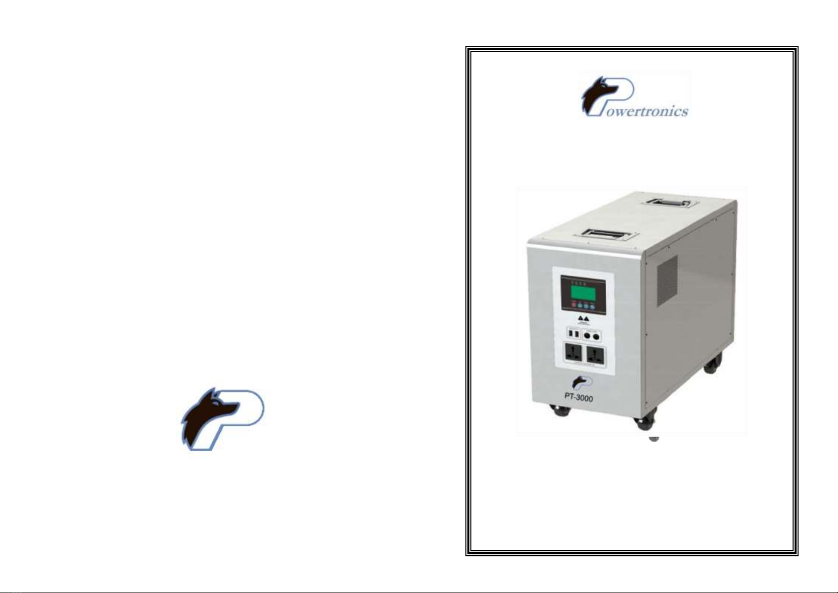
Thank you very much for purchasing Powertronic’s PT-3000. Before use of
this product, please read the user manual fully. Please feel free to
contact ourcustomer service department if you have any questions. It is also
suggested you keep this user manual in the event more detailed information
is needed in the future.
Catalogue
1、Product Features......................................................................................1
2、Installation and storage Guide..................................................................1
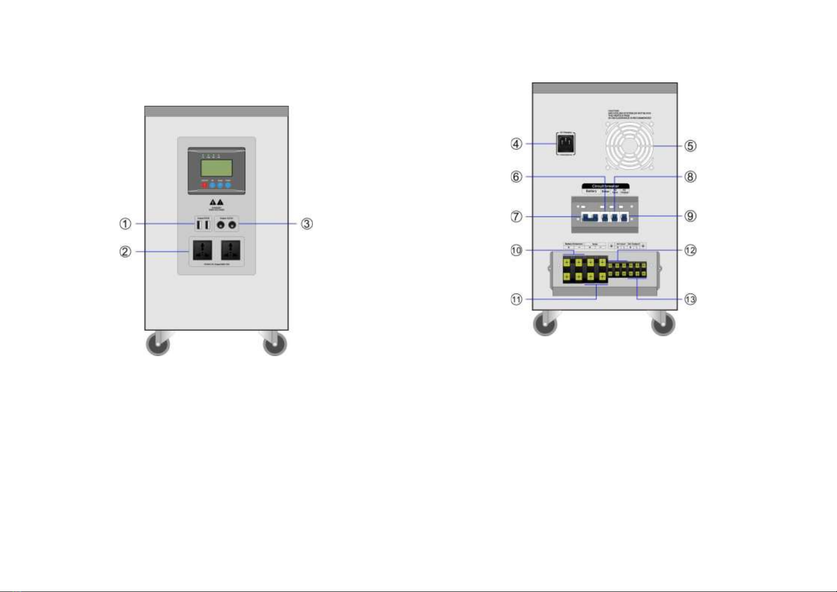
3、Equipment diagram, operation instructions..............................................2
4、Unit connection icon...............................................................................11
5、Power ON/RUN ......................................................................................18
6、Maintenance...........................................................................................21
7、Simple fault diagnosis and troubleshooting............................................22
8、Technical data sheet ..............................................................................23
1
Product Features
●Double CPU intelligent control technology.
●2 programmable working modes, Grid power & battery power.
●Smart fan control.
●Pure sine wave output for clean and reliable power.
●Wide input voltage range, high-precision automatic voltage
output.
●LCD real-time display featuring running status at a glance.
●Battery over-voltage and low-voltage protection, overload protection, short
circuit protection, over-temperature protection
●Intelligent MPPT solar controller with over-charge & over-discharge
protection and current limiting charging protections.
2
Installation & Storage Instructions
2.1 Out of Package Inspection
2.1.1 Open and inspect the equipment for damage, please ensure the Quick
Start and user manual are present.
2.1.2 If the equipment is damaged in transit, such as damaged or missing
parts, do not power on, report the damage to carrier and dealer.
2.2 Installation, Storage Precautions
2.2.1 Installation of equipment should be conducted by a qualified technician.
2.2.2 Transport of equipment, from low temperature to high temperature
environments may cause condensation, before using, equipment must be
completely dry to ensure safety.
2.2.3 Do not expose the equipment to wet, flammable, explosive or a high
dust accumulation environment; do not cover or block the vents, 4 inches of
aircirculationspace requiredforperipheral equipmentinordertohave proper
heat dissipation.
2.2.4 When the equipment is not in use, turn off all the breakers.
-1-

3
Unit Diagram/Operation Instructions
3.1 Front panel icons
3.2 Side Panel Icons
Guide
①-- 5VDC Output (USB sockets)
②-- AC Outlets
③-- 12VDC Output
Guide ④-- AC Input Socket (AC charger)
⑤-- Cooling Fan
⑥-- Solar Input Breaker
⑦-- Battery Input Breaker
⑧-- AC Input Breaker
⑨-- AC Output Breaker
⑩-- External Battery Input Terminals
⑪-- Solar Input Terminals (Solar Charger)
⑫-- AC Input Terminals
⑬-- AC Output Terminals

-2- -3-

3.3 Front Panel Instructions
3.3.1 LCD display and operation interface, displays the working status of the
equipment, including Input/output voltage, frequency, main mode, inverter
mode, battery capacity, charge current, total charge load capacity and
warnings.
3.3.2 Keys Description
Function keys
Description
Power ON/
OFF
Press and hold for 2s to switch between ON and
OFF.
Page up/set
key
Under the main screen, click to view the unit
parameters and set increments
Scroll
down/set
key
Under the main screen, click to view the unit
parameters and set the decrements
Function
keys
Press and hold to enter unit mode settings.
Under settings screen, press to confirm the
parameters and return to the main
screen.
-4-
3.3.3 LED Status Description
LED display
Description
PV
Green
Light
PV start charging
OFF
PV stop charging
LINE
Green
Light
AC is connected and the output is bypassed
OFF
No input AC power is connected or the unit is
under inversion mode.
INV
yellow
Light
The unit is under inversion mode.
OFF
The unit is not under inversion mode.
FAU
red
Light
AC output overload or Inverter fault
OFF
The unit is working normally.
-5-

3.3.4 LCD Display Instruction
3.3.4.1 View themain screen:press DOWN or UP to scroll through the
screens.
-6-
3.3.4.2 Main Menu: From the main screen, press and hold Function
key for 5 seconds to enter the main menu, press DOWN or UP to
view the sub-menu. The function of P0/P1/P2/P3/P4 when flashing is
as follows:
Main Menu
Functions
P4
Buzzer mode
P3
Inverter charging current
P2
-------------------------------
P1
Inverter operating mode
P0
Save & Exit
-7-

3.3.5 Parameters Setting
3.3.5.1 Buzzer Settings
Under the main screen, Press and hold the Function button for 5 seconds to
enterthe main menu, press the DOWN button to select the buzzer
information P4,press the Function button to enter the setting interface, turn
on/off the buzzer state through DOWN or UP key, and press the Function
key to save and exit. On Indicates that the buzzer is on, 0FF Indicates that
the buzzer is off.
3.3.5.2 InverterAC Charging Settings
In the main screen, press and hold the Function button for 5 seconds to
enter the main menu. Press the DOWN button to select inverter charging
information P3. Press the Function button to enter the setting interface
through DOWN or UP keys, increase/decrease the charge current of the
inverter (100%-80%-60%-40%-20%). Press Function to save and exit.
-8- -9-

3.3.5.3 Inverter Working Mode Settings
Under the main screen, press and hold the Function key for 5 seconds or
less to enter the main menu, press the DOWN key to select the inverter
work modeinformation P1, press the Function key to enter the setting
interface, adjust the inverter work mode (01-03) through DOWN or UP key,
press the Function key to save and exit.
con
Working
mode
Running state
01
The grid
priority
mode
(Default)
Under working mode 01, grid power bypasses the
inverter to the load while also charging the battery.
When the grid is over-voltage, low-voltage or has
serious distortion,the unit will transfer to battery
power supply. When the grid power is back to
normal, the unit will transfer back
to grid power bypassing.
03
Battery
priority
mode
Under working mode 03, grid power is not charging the
battery. The unit can be charged via Solar charger only
as Solar and battery are the main power sources. Solar
charge the batteries and supply the power to the loads
through the inverter. When the battery is discharged to
the low-voltage protection threshold, the unit will transfer
to gridpower bypassing (if grid power is available).
When the battery is fully charged, the unit will transfer
back to battery power supply.
-10-
4
Unit connection icon
4.1 Recommended Line Diameter
Battery, AC input / output connecting wire diameter recommendations.:
(1mm 2 copper wire is calculated by current 4-5A)
For example: 5000W/48VDC/220VAC equipment connecting wire diameter
are as follows
-11-

4.2 System working diagram
4.3 Instructions for Solar Power Input
Use the correct size of PV cable, make sure the solar power voltage and
wattage are in range of unit allowance. Wire solar to the "⑪--Solar input
terminals" . Make sure the positive (+) and negative (-) of the solar are wired
correctly. Wrong polarity may cause the unit damage. Turn on the “⑥
--Solar Input Breaker”
-12-
4.4 Instructions for Connecting Expansion Battery
The external battery’s voltage must be consistent with the unit’s internal
battery voltage: 51.2V. Make sure the positive (+) and negative (-) terminals
are wired correctly. Reversing polarity may damage the unit.
4.5 Instructions for AC Input
The unit has 2 ways for AC input wiring,
“
④-
AC
Input
Socket”
and
“
⑫
-
AC
input terminals” . Please check below for details.
-13-
WARNING!!! VERY IMPORTANT!!!
DO NOT connect “AC Input Socket” and “AC input
terminals” at same time! It may cause a short circuit and
damage the unit.
“AC Input Socket” and “AC input terminals” are
designed as an either-or and are for differentpurposes of use.

When you want to use wall power to charge the unit, Turn on “⑧-AC input
breaker” and battery breaker THEN plugthe AC powercordinto”④-ACInput
Socket” and plug the other end into the wall outlet or a generator.
AC Input
MAX 10A
disconnect
VERY IMPORTANT NOTE:
DO NOT connect “④-AC Input Socket” and “⑫-AC input terminals” at
same time! It may cause short circuit and damage the unit.
④
and
⑫
are the EITHER-OR option for AC input.
The “④-AC Input Socket” and “⑫-AC input terminals” are in parallel.
Maximum current of “④-AC Input Socket” is 10A. Maximum current of “⑫
-AC input terminals” is 30A.
-14-
When you want to use the unit as an uninterrupted backup power to your
loads, you are suggested to wire theAC input with terminals. Use the correct
size of AC power cable (2.5mm² or bigger), make sure the AC power voltage
is in the range of unit allowance. Turn on “⑧-AC input breaker” and battery
breaker THEN wire AC power source to the “⑫-AC input terminals” .
VERY IMPORTANT NOTE:
DO NOT connect “④-AC Input Socket” and “⑫-AC input terminals” at
same time! It may cause the short circuit and damage the unit.
④
and
⑫
are the EITHER-OR option for AC input.
The “④-AC Input Socket” and “⑫-AC input terminals” are in parallel.
Maximum current of “④-AC Input Socket” is 10A. Maximum current of “⑫
-AC input terminals” is 30A.
-15-
AC Input
MAX
disconnect

4.6 Outputs
4.6.1 AC outputs
The AC loads are connected to the “②/⑬-- AC Output” outlets on the front
panel. The total AC loads power should be no more than the inverter rated
power.
-16-
4.6.2 DC outputs
The 5VDC loads are connected to the “①- 5VDC Output”(USB souckets)
on the front panel. The total 5VDC USB output current is 2A.
The 12VDC loads is connected to the “③- 12VDC Output” on the front panel.
The total 12VDC output current is 2A.
Make sure the positive (+) and negative (-) of the DC loads are wiring
correctly before plug in. DC output short circuit may cause the unit damage.
-17-
AC Output
MAX 15A
AC Output
MAX
12VDC
LOAD
5VDC
LOAD

5
Power ON/RUN
5.1 Inverter Power ON/RUN
5.1.1 Battery starting
Turn on the battery breaker, press and hold the "ON / OFF" button on the
operation panel for 2 seconds, release it after the buzzer beeps. The "INV"
indicator light lights, turn on the A/C out breaker.
5.1.2 AC Input Power-on
Connect AC input (Utility or Generator), the "LINE" indicator light turns on,
turn on the A/C input breaker.
5.2 Solar Charge Controller
Make sure the solar power voltage and wattage are in range of unit design.
Wire solar panels to the “Solar Input Terminals”, turn on the “Solar Input
Breaker”. When the solar panels are exposed to sunlight, the "PV" indicator
light on. The solar power is charging the batteries through the MPPT solar
charge controller.
-18-
5.3 Shutdown
Shutdown: Turn off the loads, disconnect themains input, and then press the
"power on / off button" for 2 seconds, release after the internal relay action,
the unit AC output is off, LCD screen turned off, turn off all the breakers;
5.4 Battery protection table
When the AC output is turned on, the relevant protections must beexecuted
when the battery voltage reaches the value in the table below.
Inverter protection voltage parameters
Overvoltage
protection
Overvoltage
recovery
Low-voltage alarm
Low-voltage
protection
71.6VDC
68.2VDC
46.0VDC
44.8VDC
Disconnect the
AC output
Restore AC
output
Keep AC output
Disconnect battery
output. Transfer to
Utility power if
applicable.
-19-
Note: Check and make sure the voltage and polarity of battery and
solar panels are connected correctly.
OPERATION PRECAUTIONS: To start the unit, do it according to the
following steps: Turn on the battery circuit breaker, then turn on the
solar input breaker. To shut down the unit, turn off the solar input
breaker, then turn off the battery breaker
Caution: If the unit is idle for long time, please turn off the battery
breaker to avoid the battery deep discharging unless the solar power
or AC charger is connected to maintain the battery.

5.5 Audio alarm reminder instruction
Equipment
running normal
Buzzing
prohibit
Buzzer is no tweet under default
status.
Buzzer
starts
Buzzer tweet 4 times every 15s,
indicate the equipment operated
under battery inverter status.
Battery high
voltage alarm
Buzzer tweets 4 times per second, alarms high
voltage
Battery low
voltage alarm
Buzzer tweets 2 times per second, alarms low
voltage
Over
temperature
alarm
Buzzer alarm 2 seconds pause 1 second
5.6 Electric Generator Connection Announcements:
When connecting an electric generator:
5.6.1 Make sure the generator output voltage is matched to the MPS unit
AC input range. Turn off all the AC switches, wire the generator output to
MPS unit AC input terminals according to the instructions. Start the
generator andhave it running stable. Then make sure the unit output has
no-loads connected. Then start the unit.
5.6.2 After the unit is started, connect the loads one by one.
5.6.3 We suggested generator capacity be 2~3 times that of this unit.
-20-
6
Maintenance
6.1 This series of product requires little maintenance, battery only needs
to maintain its charge for full life expectancy.
6.2 If you do not use the equipment for a long period of time, it is
recommended it be charged every 4-6 months. Under normal
circumstances,the battery’s life will be 3-5 years, if found in poor condition,
you must replace the battery early. Replacement of the battery must be
carried out by qualified personnel. Battery should not be individually
replaced; the overall replacement should follow the battery supplier's
instructions.
6.3 In moderate climates every 4 to 6 months the battery must be discharged
to shut down and recharged to full capacity. In high temperature regions the
battery discharge and charge should be done every 2 months.
6.4 Before replacing the battery, turn off the device and disconnect it from
the main and close the batteryswitch.Remove allmetal objects such as rings
and watches. Use insulated handles and screwdrivers, do not put tools or
other metal objects on the battery pack.
6.5 When connecting the battery cable, it is normal for small sparks to
appear which will not cause any harm to equipment or the personal safety
andthe operator. Do not cross connect the battery terminals.
-21-

7
Simple Fault Diagnosis and Trouble Shooting
WARNING: There is high voltage inside the machine! Do not open and
try to repair or maintenance, high voltage may cause shock or death!
Failure
Possible reason
solution
unit won’t charge
A/C in breaker not on
Make sure that the
Breaker is fully on
Fuse Blown
Change fuse in 10A
port
Improper charge
procedure
Ensure to turn on
battery and A/C
breakers and power on
unit before plugging in
Won’t Power on
The mains input cable or
the battery cable is
poorly connected
Check and reconnect
Boot alarm
The battery is low
Make sure that the
battery is fully charged
Load overload
Removal of noncritical
loads
The buzzer buzzes
for 2seconds then 1
second
The internal temperature
is too high alarm
Check the fan and
cooling holes are
blocked
Short Run Time
Battery not
charged or
overloaded
Make sure battery is
fully charged and does
not have too high of
load
The "PV" indicator
does not light when
there is a sun-lit PV
module
Solar cable connection
Please check whether
the wiring of the Solar
array is correct and the
contact is reliable
When you contact the service staff, please provide the following information:
Type of unit / date of issue / complete description of the problem (including
the relevant indicator display status, battery configuration, connection).
-22-
8
Technical Data Sheet
Model
3KW
Battery rated voltage(vdc)
51.2
Inverter
Rated power(w)
3000
Input voltage range(vac)
85-138VAC
Input frequency(Hz)
45-65
Output voltage(vac)
110
Output frequency(Hz)
50/60
Output wave
Pure Sine Wave
Specification of built-in battery
1*100Ah
MPPT
Solar
input
MPPT Voltage Range
60V~150VDC
PV Power
2600W
Rated charge current
50A(Max)
MPPT efficiency
≥99%
Floating charge voltage
56.8VDC
DC
output
Low voltage recovery voltage
53.6VDC
Low voltage protection voltage
44.8VDC
5VDC USB output
2 units / MAX 2A
12VDC output ports
2 units /MAX 10A
Heat dissipation/Cooling
Temperature control by intelligent
exhaust fan
Operating ambient temperature
-20 - +50℃
Storage ambient temperature
-25 - +55℃
Operating/Storage ambient
0-90% No condensation
External size:W*D*H(mm)
613*275*511
Package size:W*D*H(mm)
730*710*670
Note: We reserve the right of modifying this user manual without any notification.
-23-
Table of contents
Other Power-Tronics Industrial Equipment manuals
Popular Industrial Equipment manuals by other brands

woodmizer
woodmizer LT35 Safety, Installation, Operation, Maintenance & Parts Manual

Alfalaval
Alfalaval ALS Series instruction manual

Home Fires
Home Fires Skytech 4000 Series troubleshooting guide

Alfalaval
Alfalaval Toftejorg MultiJet 50 instruction manual

woodmizer
woodmizer LT30 Safety, Setup, Operation & Maintenance Manual

Metalworks
Metalworks CAT410 manual