Trace Sun Tie ST1000 Setup guide
Installation and Operators Manual
ã
2000 Xantrex/Trace Engineering
Sun Tie Inverter
ST1000, ST1500, ST2000 and ST2500
975-0003-01-02 Rev. A 11/00


i
©2000 Xantrex/Trace Engineering
Sun Tie Inverter
ST1000, ST1500, ST2000 and ST2500
Table of Contents
Section Description Page
1.0 INTRODUCTION .....................................................................................1
Standard Features ...........................................................................1
.0 INSTALLATION .......................................................................................
Pre-Installation ................................................................................
Tools Required ..........................................................................
Hardware/Materials Required ..................................................
AC Connections ........................................................................
DC Connections ........................................................................ 3
ST1500 and ST 500 ............................................................3
ST1000 and ST 500 ............................................................4
Grounding .................................................................................5
AC Grounding .....................................................................5
DC Grounding .....................................................................5
PV Arrays ................................................................................... 5
AC Circuit Breakers ..................................................................6
Wire Routing .............................................................................6
Mounting ..........................................................................................7
Wiring ........................................................................................... 11
DC Wiring ................................................................................ 11
PV Array ................................................................................... 11
ST1500 and ST 500 DC Wiring ....................................... 11
PV Array Conduit/Wire Run ............................................. 11
ST1000 and ST 000 DC Wiring .......................................13
PV Array Conduit/Wire Run .............................................13
AC Wiring ................................................................................14
Lightning Protection ............................................................... 17
3.0 OPERATION .........................................................................................18
Start-up Procedure ........................................................................ 18
Required Equipment ............................................................... 18
AC Utility Voltage Check ........................................................ 18
Solar Array DC Voltage Check ...............................................19
Operational Test ...................................................................... 0
4.0 TROUBLESHOOTING .......................................................................... 4
5.0 SPECIFICATIONS ................................................................................. 7
6.0 SERVICE INFORMATION ..................................................................... 8
7.0 WARRANTY.......................................................................................... 9

©2000 Xantrex/Trace Engineering
ii
Disclaimer of Liability
Since the use of this manual and the conditions or methods of installation, operation, use and
maintenance of the unit are beyond the control of Xantrex/Trace, the company does not assume
responsibility and expressly disclaims liability for loss, damage, or expense arising out of or any way
connected with such installation, operation, use, or maintenance.

©2000 Xantrex/Trace Engineering iii
SAVE THESE INSTRUCTIONS
IMPORTANT SAFETY INSTRUCTIONS
This manual contains important safety instructions that should be followed during the installation
and maintenance of this product.
To reduce the risk of electrical shock, and to ensure the safe installation and operation of this
product, the following safety symbols have been placed throughout this manual to indicate
dangerous conditions and important safety instructions.
WARNING - A dangerous voltage or condition exists in this area.
se extreme caution when performing these tasks.
AVERTISSEMENT - ne tension ou condition dangereuse existe dans cette zone.
Faire preuve dextrême prudence lors de la réalisation de ces tâches.
CAUTION - This procedure is critical to the safe installation or operation of the unit. Follow these
instructions closely.
ATTENTION - Cette procédure est essentielle à linstallation ou lutilisation
de lunité en toute sécurité. Suivre ces instructions de près.
NOTE - This statement is important. Follow instructions closely.
NOTE - Cette déclaration est importante. Suivre les instructions de près.
All electrical work must be done in accordance with local and national electrical codes.
Before installing or using this device, read all instructions and cautionary markings located in
(or on) the manual, the ST and the PV array.
Do not expose this unit to rain, snow or liquids of any type without the rain/weather shield
hood installed (optional on some models).
To reduce the chance of short-circuits when installing or working with the inverter or the PV
array, use insulated tools.
Remove all jewelry such as rings, bracelets, necklaces, etc., prior to installing this system.
This will greatly reduce the chance of accidental exposure to live circuits.
The ST unit contains more than one live circuit (PV array and AC line). Power may be present
at more than one source even when the circuit breakers are off.
This product contains no user serviceable parts. Return the unit to a Trace Authorized Service
Center for maintenance.
Wiring to the utility should only be done after receiving prior approval from the utility company
and performed only by a qualified electrician.
Completely cover the surface of all PV arrays with an opaque (dark) material BEFORE wiring
them. PV arrays produce electrical energy when exposed to light, and could create a
hazardous condition.

©2000 Xantrex/Trace Engineering
iv
NOTE: This is a one line drawing intended as a system overview only. System grounding and other
electrical details are not included.
DC Input Voltage AC Output
Voltage
Main Utility
Service Panel
AC Utility
Meter
Solar Power
AC to Grid
Solar PV Array
975-F00-008SA
ON
OFF
ON
OFF
ON
OFF
ON
OFF
ON
OFF
ON
OFF
ON
OFF
ON
OFF
ON
OFF
ON
OFF
ON
OFF
ON
OFF
ON
OFF
ON
OFF
Sun Tie
Sun Tie Unit

1
1.0 INTR DUCTI N
©2000 Xantrex/Trace Engineering
The Trace Sun Tie (ST) solar power conversion center is designed to convert a home or
business into a green power generating station. The ST unit converts solar electric (PV) power into
utility grade electricity which can be used by the home, or sold to the power company. Installing an
ST unit is as simple as mounting it to the wall and connecting a DC source (PV array), and the AC
output to the utility.
Standard Features
All-in-one Design
All necessary DC input and AC output connections, disconnects and circuit breakers are housed
within the STs easily installed, compact enclosure. A built-in LCD panel provides easy-to-read
system status and daily cumulative energy production information.
Uses Most Types of PV Technology
The ST is designed to take advantage of most types of solar electric technologies. The inverter
allows up to 120 VDC open circuit PV modules to be used so both crystalline and thin film PV
modules can be used.
Maximum Power Point Tracking
The inverter performs a power sweep every minute adjusting array voltage and current,
maximizing PV power generation. Maximum Power Point Tracking (MPPT) ensures the system
produces as much AC power as possible under any light condition.
High Efficiency and Long Life
The high frequency, solid-state design of the ST inverter is extremely efficient. When array
output is over 500 watts, the inversion process is over 90% efficient (with a peak efficiency of 94%).
The ST inverter has a design life of over twenty years.
Expandable
ST inverters may be connected in a parallel configuration for increasing net metering capacity.
The modular expandability of the ST Series allows for system growth.
UL Listed
The ST has complete on-board islanding protection and meets safety operating standards and
code requirements world wide. In North America, it is L listed ( L 1741-First Edition) and c L listed
to CSA C22.2 No. 107.1-95. NEC 690 building code requirements for PV may be met with the
optional ground fault protection (PVGFP).
Options
These features are included on some models:
PV array combiner board with six 20 amp max. protected inputs
PV array Ground Fault Protection PVGFP
2.0 INSTALLATI N
©2000 Xantrex/Trace Engineering
Pre-Installation
Before installing the Trace ST unit, read all instructions and cautionary markings located in
this manual, on the PV array and on the main service panel.
NOTE: The Trace ST weighs approximately 35 pounds (depending upon configuration and model).
Always use proper lifting techniques during installation to prevent personal injury.
Mounting:
The Trace ST unit can be mounted outdoors with the optional Rain Shield (STRS).
Tools required:
Phillips screw drivers level
slotted screw drivers wire strippers
open-end wrenches torque wrench
socket wrench and fittings electrical tape
multimeter (true rms) pencil
frequency counter (optional) utility knife
Hardware/Materials required:
wood screws and washers (supplied)
conduit and appropriate fittings
anchors for screws (material dependent)
AC Connections:
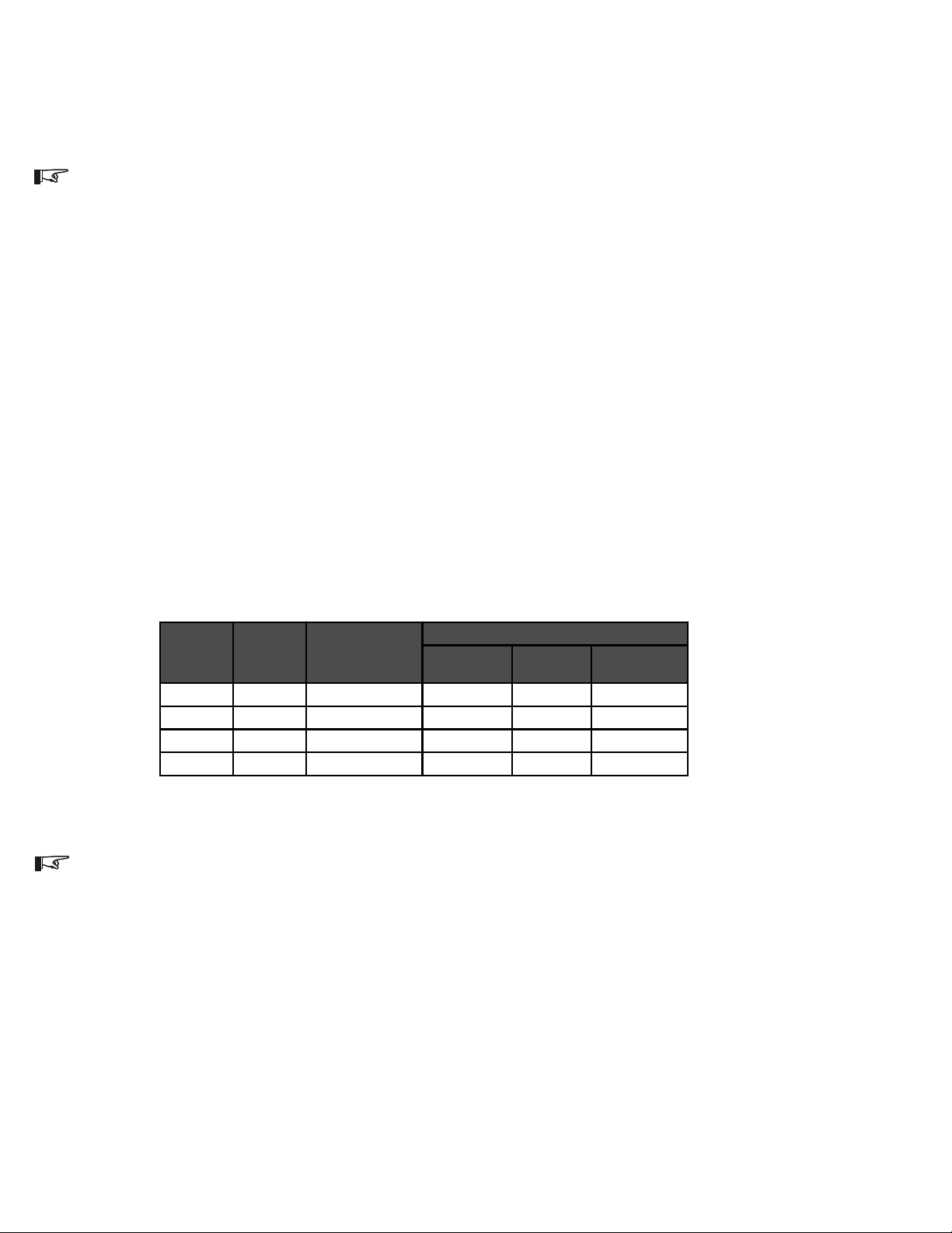
The inverters AC output breakers accept wire sizes from #614 AWG. Refer to the table
below for minimum recommended wire size.
Inverter
Model
AC Amps
Output per
leg
NEC Amp
(Amps *125%)
Minimum Wire Size for Specified Distance
0–50 Ft
One Way 50–100 Ft
One Way 100–200 Ft
One Way
ST1000 4.2 5.2 14 AWG 14 AWG 12 AWG
ST1500 6.3 7.8 14 AWG 12 AWG 10 AWG
ST2000 8.3 10.4 14 AWG 12 AWG 10 AWG
ST2500 10.4 13 14 AWG 12 AWG 8 AWG
975-000-001
Table 1
Recommended Minimum AC Wire Sizes
NOTE: These are the minimum recommended wire sizes in conduit. Installing a large number of
wires in conduit or enclosed locations may require larger wire sizes. Consult your local/national
electrical code for more information.

3
2.0 INSTALLATI N
©2000 Xantrex/Trace Engineering
Pre-Installation (continued)
DC Connections:
ST1500 and ST 500
DC connections are made on the combiner board for models ST1500 and ST2500. The
combiner board accepts wire sizes from #614 AWG. Refer to the table below for minimum
recommended wire sizes.
DC Amps NEC Amp
(Amps x 156%)
Minimum Wire Size for Specified Distance
0–25 Ft
One Way 25–50 Ft
One Way 50–100 Ft
One Way
1.0 1.6 14 AWG 14 AWG 14 AWG
3.0 4.7 14 AWG 12 AWG 10 AWG
5.0 7.8 12 AWG 10 AWG 6 AWG
7.0 10.9 12 AWG 8 AWG 6 AWG
9.0 14.0 10 AWG 8 AWG Not Recommended
11.0 17.2 10 AWG 6 AWG Not Recommended
975-000-002
Table 2
Recommended Minimum DC Wire Sizes
NOTE: These are the minimum recommended wire sizes. Installing a large number of wires in
conduit or enclosed locations may require larger wire sizes. Consult your local/national electrical
code for more information.
NOTE: The National Electrical Code (NEC) places restrictions on minimum DC wire bending radius.
A #6 AWG wire is the largest that may be used on the ST1500 and ST2500 inverters.
Figure 1
Combiner Board Indicating DC P Array Wire Connection Points
PV array iring
(note polarity)
DC conduit iring
(from solar arrays)

4
2.0 INSTALLATI N
©2000 Xantrex/Trace Engineering
Pre-Installation (continued)
DC Connections:
ST1000 and ST 000
DC connections are made at the 100 amp DC circuit breaker and the DC negative terminal
block for models ST1000 and ST2000. Refer to the table below for minimum recommended wire
sizes.
DC Amps
(from PV array) NEC Amp
(Amps x 156%)
Minimum Wire Size for Specified Distance
0–25 Ft
One Way 25–50 Ft One Way 50–100 Ft
One Way
10 15.6 10 AWG 6 AWG 4 AWG
15 23.4 8 AWG 4 AWG *2 AWG
20 31.2 6 AWG 4 AWG *1 AWG
30 46.8 4 AWG *2 AWG Not Recommended
40 62.4 4 AWG *1 AWG Not Recommended
60 93.6 *2 AWG Not Recommended Not Recommended
975-000-004
Table 3
Recommended Minimum DC Wire Sizes
*NOTE: The National Electrical Code (NEC) places restrictions on minimum DC wire bending radius.
If the enclosures side is used for routing the wires to the DC terminals, then the wires must be bent
to make the appropriate connections. A #3 AWG wire is the largest that may be used on the ST1000
and ST2000 inverters if the side panel is used. Side knockouts are NOT provided on the unit.
Figure 2
DC P Array Wire Connection Points
(with no combiner board)
PV array Negative iring
PV array Positive iring
5
2.0 INSTALLATI N
©2000 Xantrex/Trace Engineering
Pre-Installation (continued)
Grounding:
AC Grounding
The Trace ST unit should be connected to a grounded, permanent wiring system.
DC Grounding
The negative PV conductor should be bonded to the grounding system at only one point in the
system. The size for the conductor is usually based on the size of the largest conductor in the DC
system. Negative/ground bonding is accomplished by factory wired PVGFP breakers (when this
option is installed) or a factory installed grounding block (when PVGFP is not installed).
PV Arrays:
The ST unit is optimized to work with 4-each, 12 volt nominal crystalline PV modules in series
(48 VDC nominal), or various combinations of amorphous, thin film PV modules. Ensure the PV
array used in the system operates within the MPPT operational window.
The solar array connected to the ST Series inverter should have a minimum of 50 volts DC
open-circuit in full sunlight conditions. Crystalline solar arrays configured for 48 volts DC nominal will
have a open-circuit voltage in the area of 84 volts DC in full sunlight. The maximum peak power
tracking (MPPT) software controls the output of the solar modules, under loaded conditions, in the
42-85 volts DC range (full inverter output power occurs between 5285 VDC). Other array voltage
will either not operate the inverter or will not allow maximum harvest of the suns energy.
WARNING: WHENEVER A PV ARRAY IS EXPOSED TO SUNLIGHT, A SHOCK HAZARD EXISTS
AT THE OUTPUT CABLES OR EXPOSED TERMINALS. TO REDUCE THE RISK OF SHOCK
DURING INSTALLATION, COVER THE ARRAY WITH AN OPAQUE (DARK) MATERIAL BEFORE
MAKING ANY CONNECTIONS.
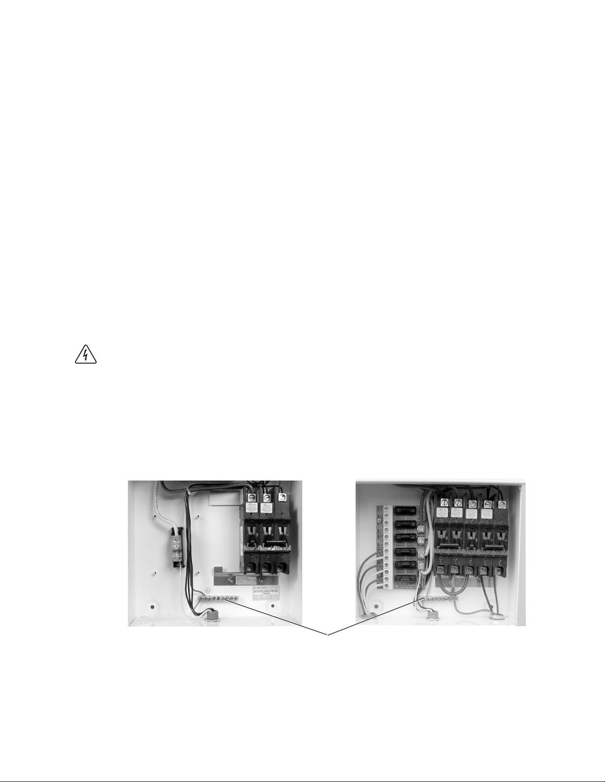
Figure 3
Ground Bar Location
Ground Bar Location
(connect to solid earth ground)
ST1000 and ST2000 Models ST1500 and ST2500 Models
6
2.0 INSTALLATI N
©2000 Xantrex/Trace Engineering
AC Circuit Breakers:
The main service panel must dedicate a 15 amp minimum, double pole breaker (120/240 volts
AC) to operate the ST unit.
Wire Routing:
Determine all wire routes both to and from the Sun Tie. Possible routing considerations include:
AC input wiring from the main service panel to the ST
DC input wiring from the PV array to the ST
DC ground from the PV array to an external ground rod
All wiring and installation methods should conform to applicable electrical and building codes.
Pre-plan the wire and conduit runs. The DC terminal blocks accept up to a #6 AWG wire
(ST1500 and ST2500) and #2 AWG* wire (ST1000 and ST2000); the AC circuit disconnects
accept cable sizes up to #6 AWG.
For maximum safety, run AC and DC wires/cables in (separate) conduits.
*NOTE: #2 AWG wire can only be used if the bottom knockouts are used. If punching side walls for
wire routing, the largest wire for acceptable wire bend radius is #3 AWG maximum.
WARNING: CHECK FOR EXISTING ELECTRICAL OR PLUMBING PRIOR TO DRILLING HOLES
IN THE WALLS!

7
2.0 INSTALLATI N
©2000 Xantrex/Trace Engineering
Mounting:
The ST unit must be mounted to a flat, vertical surface such as wallboard or wood siding.
Installation onto wallboard or concrete requires the use of anchors to properly hold the screws.
Outdoor installation requires the use of the optional rain shield (STRS) to prevent water from enter-
ing the unit.
WARNING: DO NOT INSTALL THE SUN TIE UNIT OUTDOORS WITHOUT THE RAIN SHIELD
HOOD. WATER ENTERING THE UNIT COULD CAUSE A DANGEROUS CONDITION AND
CAUSE THE UNIT TO FAIL. FAILURE DUE TO IMPROPER INSTALLATION WILL VOID THE
WARRANTY.
Procedure
WARNING: BEFORE DRILLING HOLES TO MOUNT THE SUN TIE, ENSURE THERE ARE NO
ELECTRICAL WIRES OR PLUMBING IN THIS AREA. SINCE THIS UNIT IS INSTALLED CLOSE
TO THE UTILITY ENTRANCE OR METER, THERE MAY BE A HIGH CONCENTRATION OF
ELECTRICAL WIRES IN THE AREA.
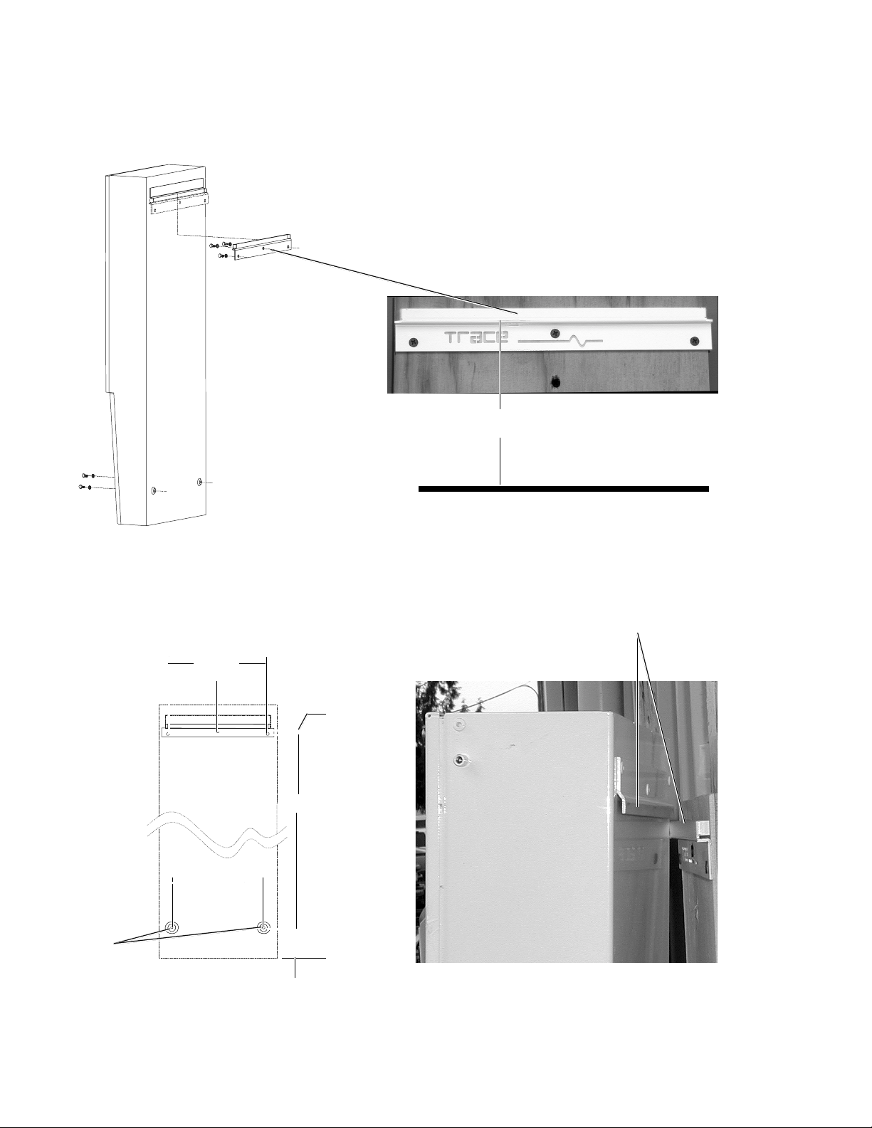
1. Locate the area where the ST is to be installed. It should be as close to the utility service panel as
possible. The bottom of the unit must be at least 36 inches from the floor or ground when
mounted.
. sing a level, place the mounting bracket up to the wall (in a horizontal position) and mark the
area for the three screws (Figure 4A). To achieve the 36 inch height from the bottom of the ST
unit to the ground, mount the bracket 70 inches from the ground.
3. If required, remove the bracket and drill the holes using a #10 (0.193 inch diameter) drill bit. Drill
appropriately sized holes for anchors when installing on non-wood surfaces.
4. Mount the bracket to the wall using the screws and washers provided. If mounting to other than a
wood wall or surface, use appropriate screws and anchors if required.
5. Place the Sun Ties rear lip, located on the back top of the enclosure, over the bracket and
ensure it is seated properly (Figure 4B).
6. Remove the lower external cover to access the internal circuit breaker panel by removing the
screw on each side of the cover (Figure 5).
7. Remove the internal breaker panel by removing the screws in the breakers and two screws from
the underside of the unit, then lifting until the lower locking tabs are free, then gently pull the inner
cover outward (Figure 6). Save the screws for reinstallation.
8. After the unit is correctly seated on the upper bracket, locate the two screw holes in the bottom
(back) area of the enclosure and mark these locations on the wall (Figures 4B and 7A). Remove
the ST (if required).
9. Drill two pilot holes (as above, if required).
10. Reinstall the ST, to the bracket and secure the bottom of the unit with the wood screws and
washers provided (or appropriate screws and anchors for non-wood surfaces) and tighten
(Figures 4B and 7A).
NOTE: Mounting hardware for surfaces other than wood is not supplied.
8
2.0 INSTALLATI N
©2000 Xantrex/Trace Engineering
Figure 4A
Bracket Mounting
Mounting: (continued)
Figure 4B
Enclosure Mounting
4068-E00-002
Scre
holes
Enclosure
mounted on all
bracket
3.20"
26 - 21/32"
19/64"
8 - 55/64"
4 - 13/16"
9 - 41/64"
Slide ST enclosure lip onto bracket
4068-E00-001
Sun Tie back vie
Wall Bracket, scre s
and ashers
(supplied)
Mount 70 inches from ground

9
2.0 INSTALLATI N
©2000 Xantrex/Trace Engineering
Figure 5
Outer Cover Components
Figure 6
Inner Breaker Cover
Remove breaker scre s
Lift up and pull for ard to
remove
Remove scre s
from tabs
Locking tabs
Upper cover
External breaker cover
(remove during installation)
Remove scre s
(one on each side)
10
2.0 INSTALLATI N
©2000 Xantrex/Trace Engineering
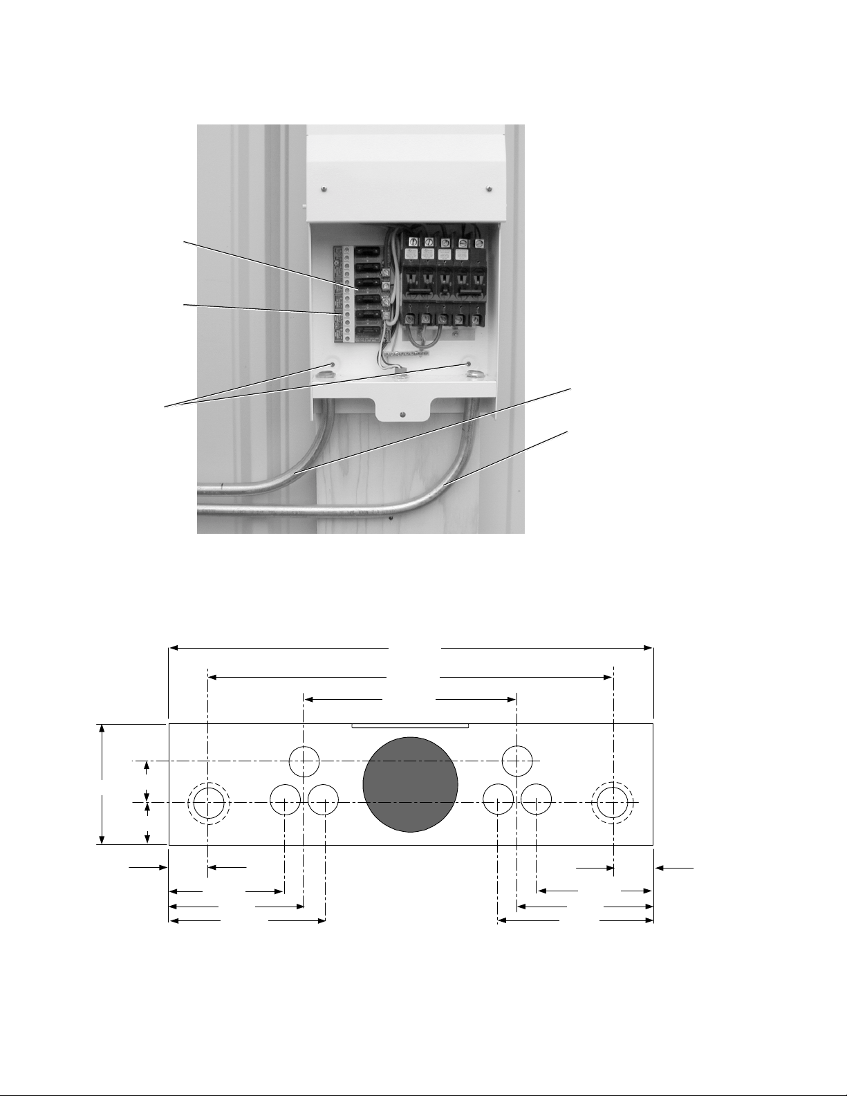
Figure 7A
Mounting Holes and AC DC Conduit in Customer Access Area
Internal mounting
holes
DC Conduit
AC Conduit
PV Combiner Board
(included on some
models)
NOTE: The internal
Combiner Board is not
available on all models.
Lightning Arrestor
5-1/64"
9-15/32"
11-13/64"
61/64"
61/64"
2-13/32"
2-13/32"
3-5/32"3-5/32" 3-23/32"
3-23/32"
27/32"
2-1/16"
3-11/32"
975-0003-D-001
Figure 7B
Conduit Hole Locations
11
2.0 INSTALLATI N
©2000 Xantrex/Trace Engineering
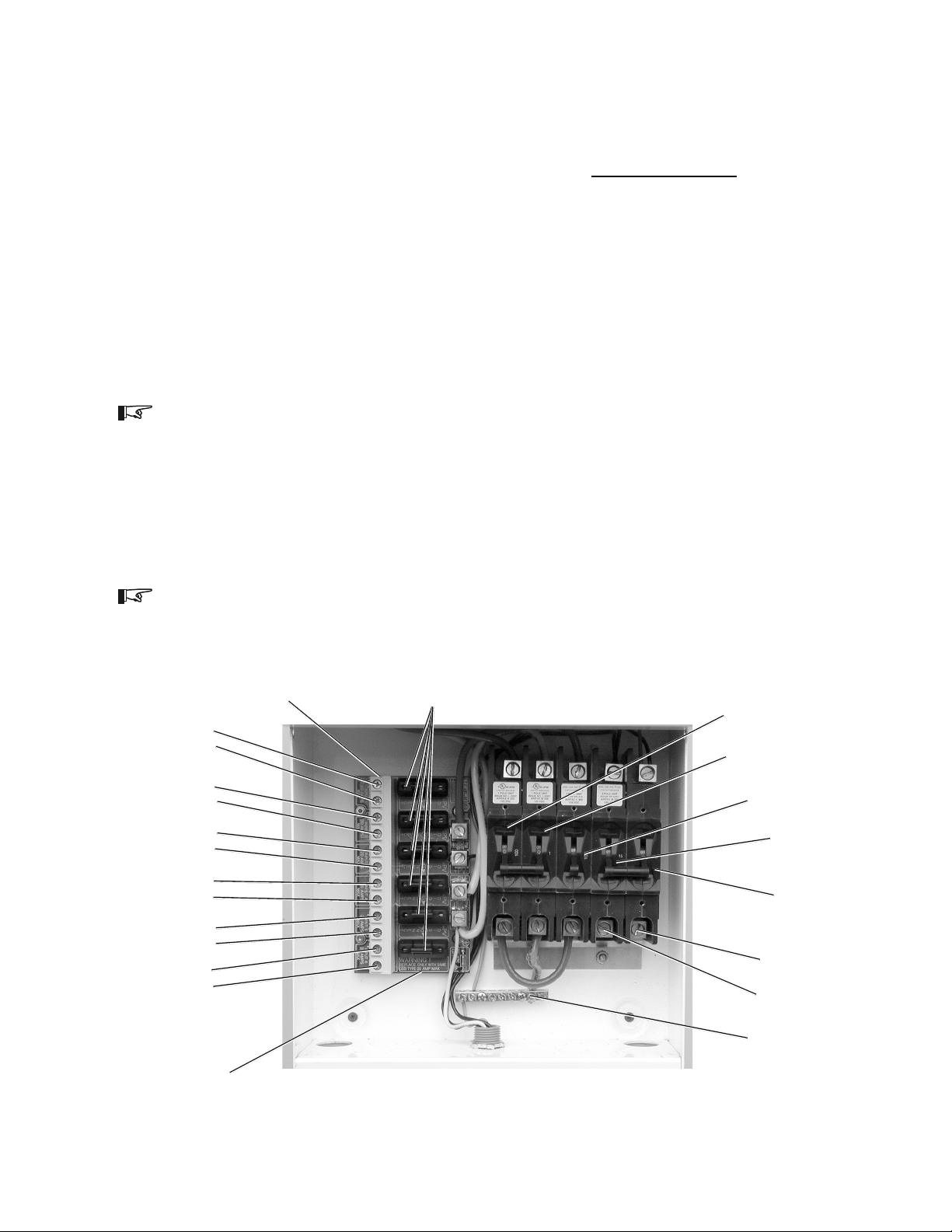
Figure 8
ST1500 and ST 500 Electrical Component Location
Wiring:
DC Wiring
The combiner board (included on some models) in the ST accepts up to six individual PV array
circuits (positive and negative wires). Each circuit on the combiner board contains a fuse to protect
against over-current. Always replace this fuse with one of the same type and rating (GBB, 20 amp
maximum, ceramic type, 0.25" x 1.25").
The combiner board PV array input connection block is located in the lower section of the ST
unit.
ST1500 and ST 500 DC Wiring (Refer to Figures 8 and 9)
PV Array Conduit/Wire Run
1. Install the DC conduit from the PV arrays to the bottom of the ST unit, via one of the knockout
holes (Figures 7A and 7B).
. Route the wires from the PV array(s) through conduit and into the lower section of the ST
enclosure (Figure 9).
NOTE: If more than one PV array is used, label the wire pairs (positive and negative) appropriately
(i.e., PV 1, PV 2, etc.).
3. Connect the positive (+) wire from the #1 array to the terminal strip labeled PV INP T 1
POSITIVE terminal. Check that the wire is in the proper location and tighten the screw.
4. Connect the negative () wires from the PV array to the PV INP T 1 NEGATIVE terminal.
Check that the wire is in the proper location and tighten the screw.
5. Repeat this procedure for each PV array circuit, connecting the #2 PV Positive wire to the
terminal labeled PV INP T 2 POSITIVE, etc.
NOTE: The solar arrays do not have to connect in the order marked on the board (this is just for
reference). All solar array positives on the combiner board are joined together AFTER the fuse.
L1 breaker
AC connection
L2 breaker
AC connection
Solar array
100 amp DC breaker
PVGFP (ganged)
1 amp DC breaker
PVGFP (ganged)
100 amp DC breaker
Solar DC terminal block
Solar input 4
+
-
Solar input 3
+
-
Solar input 2
+
-
Solar input 1
+
-
Solar input 5
+
-
Solar input 6
+
-
Solar DC Fuses
Grounding
block
L1
15 amp AC breaker
(ganged)
L2
15 amp AC breaker
(ganged)
Combiner board
1
2.0 INSTALLATI N
©2000 Xantrex/Trace Engineering
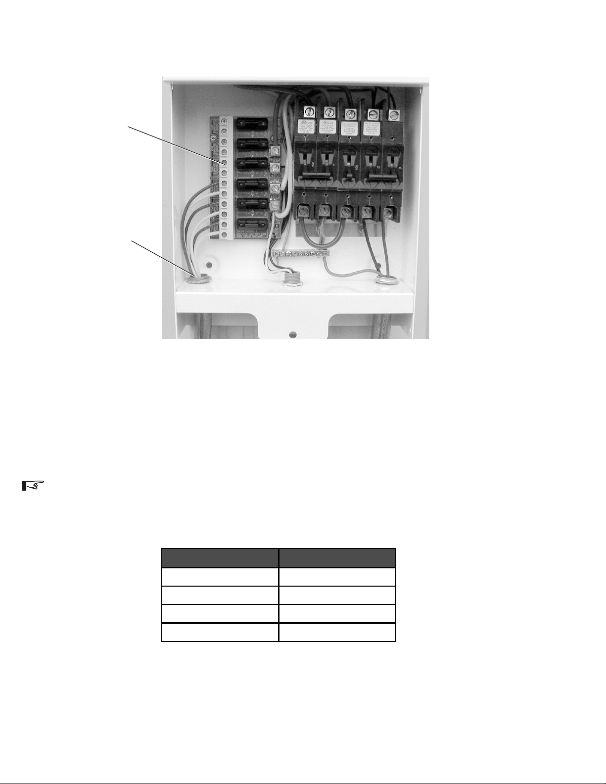
Figure 9
PV Array DC Connection Points (ST1500 and ST 500)
Wiring: (continued)
Wire Size Torque (in-lb)
14 -10 AWG 35
8 AWG 40
4 - 6 AWG 45
2 - 1/0 AWG 50
975-000-003
6. Repeat this procedure for each PV array circuit, connecting the #2 PV Negative wire to the
terminal labeled PV INP T 2 NEGATIVE, etc.
NOTE: The solar arrays do not have to connect in the order marked on the board (this is just for
reference). All solar array negatives on the combiner board are electrically tied together.
7. Torque wires according to the following table.
Table 4
Wire Torque alues
PV array iring
(note polarity)
DC conduit iring
(from solar arrays)
13
2.0 INSTALLATI N
©2000 Xantrex/Trace Engineering
Wiring: (continued)
ST1000 and ST 000 DC Wiring (Refer to Figure 10)
PV Array Conduit/Wire Run
1. Install the DC conduit from the PV arrays to the bottom of the ST unit, via one of the knockout
holes.
. Route the wires from the PV array through conduit and into the lower section of the ST
enclosure.
3. Connect the positive (+) wire from the array to the 100 amp DC CIRC IT BREAKERs lower
terminal. Check that the wire is in the proper location and tighten the screw (Figure 10).
4. Connect the negative () wire from the PV array to the DC NEGATIVE TERMINALs lower
connection. Check that the wire is in the proper location and tighten the screw (Figure 10).
5. Torque all wires according to Table 4 (previous page).
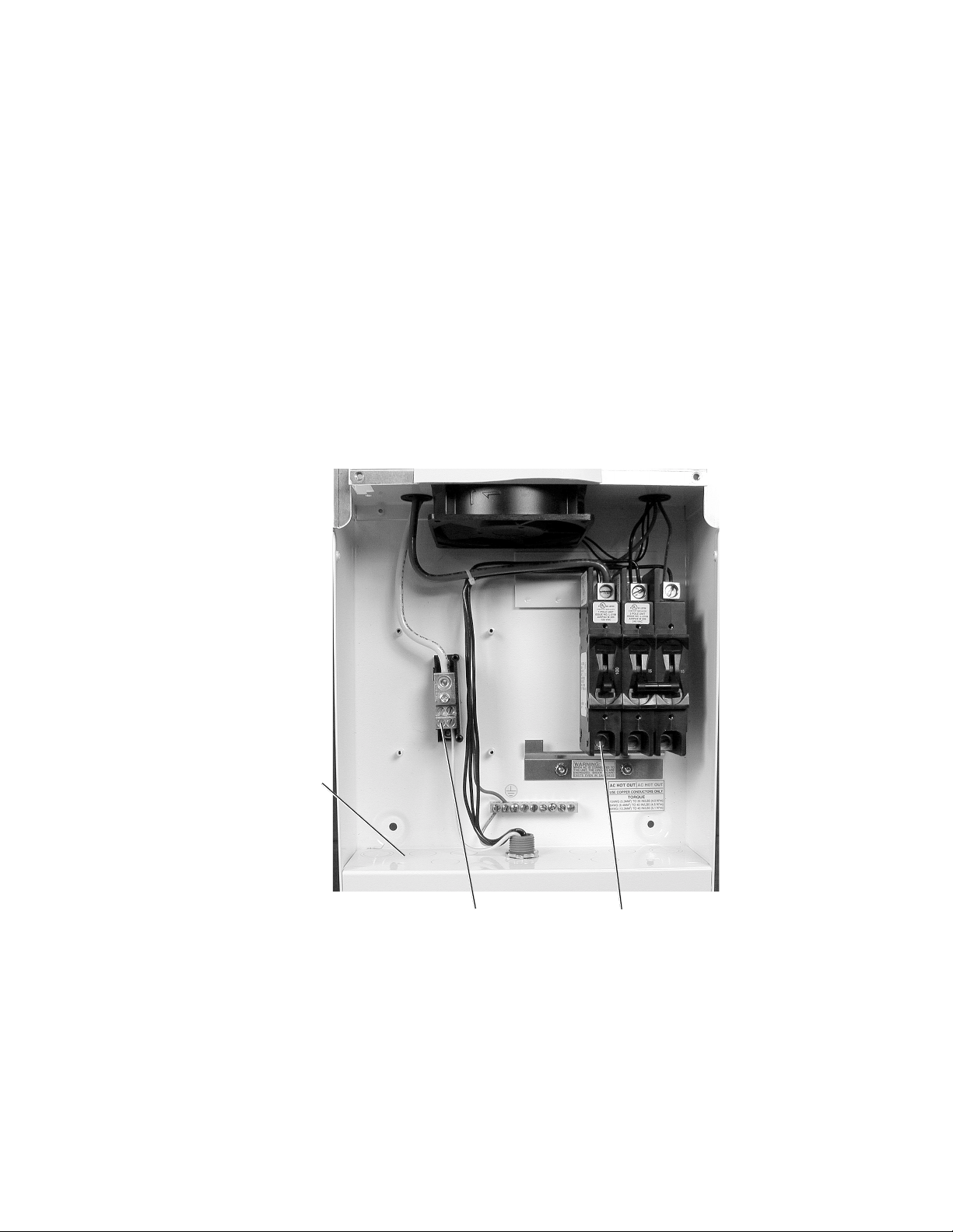
Figure 10
PV Array DC Connection Points (ST1000 and ST 000)
PV Array DC Negative
(-) Wire
PV Array DC Positive
(+) Wire
Use knockouts in lo er
section of ST for installing
conduit and routing ires

14
2.0 INSTALLATI N
©2000 Xantrex/Trace Engineering
Wiring: (continued)
AC Wiring
AC HOT wiring is connected to the ST units L1 and L2 breakers, the ground wire connects to
the GRO ND bar. All AC wiring is located in the lower section of the ST unit.
WARNING: AC UTILITY WIRING TO THE ST UNIT IS PERFORMED DIRECTLY AT THE MAIN
BREAKER PANEL. THIS SHOULD BE DONE ONLY BY A QUALIFIED UTILITY INSTALLER OR
ELECTRICIAN WITH PRIOR UTILITY COMPANY APPROVAL.
NOTE: The ST unit can be connected to a single bidirectional meter, or to dual meters, where one
meter indicates power used the second meter indicates power sold (power supplied back to the
utility). The installer and utility must determine the proper components to install.
WARNING: BEFORE WIRING THE ST UNIT, ENSURE THE MAIN 1 0/ 40 VOLT BREAKER IN
THE MAIN UTILITY BREAKER BOX IS SWITCHED OFF. SWITCH THIS BREAKER TO ON ONLY
AFTER ALL WIRING IS COMPLETED AS INSTRUCTED IN THE PROCEDURES.
1. Run conduit from the main utility breaker panel to the lower section of the ST unit. Run the
two HOT wires (L1 and L2) and ground through the conduit and into the ST units lower
section.
. Install a dual 15 amp, ganged circuit breaker in the main utility breaker panel.
3. Connect the L1 HOT wire (black) from the 15 amp, double-pole breaker installed in the main
breaker panel, to the breaker labeled L1 in the ST unit. Refer to Figure 11A for ST1500 and
ST2500, or Figure 11B for ST1000 and ST2000 models.
4. Connect the L2 HOT wire (red) from the remaining 15 amp, double-pole breaker installed in
the main breaker panel, to the breaker labeled L2 in the ST unit.
5. Connect the ground wire (green or bare copper) from the GRO ND bar in the main breaker
panel, to the GRO ND bar in the lower section of the ST unit.
6. Ensure all connections are correctly wired and properly torqued.
7. Torque wires according to the following table.
Table 5
Wire Torque alues
Wire Size Torque (in-lb)
14 -10 AWG 35
8 AWG 40
6 AWG 45
975-0003-D-003
This manual suits for next models
3
Table of contents
Popular Inverter manuals by other brands


Onan
Onan 3.0 kW AJ GEN SET Operator's manual

Fimer
Fimer UNO-DM-COM KIT Quick installation guide

Analytic Systems
Analytic Systems IPSi1200 Series Installation & operation manual

Goodwe
Goodwe EH Series Quick installation guide

Kostal
Kostal PIKO MP plus installation guide

Huawei
Huawei SUN2000 M0 Series user manual


