TrackSo WS 102 User manual

Internet of Things Solar Energy
Datasheet & Installation Guide
Wind Speed Sensor [WS 102]

Table of Contents
MODEL.............................................................................................................................................................................. 3
DATASHEET....................................................................................................................................................................... 3
Introduction.................................................................................................................................................................. 3
Specifications................................................................................................................................................................ 3
INSTALLATION .................................................................................................................................................................. 4
Guidelines..................................................................................................................................................................... 4
Tools and Materials Needed......................................................................................................................................... 4
Location Recommendation .......................................................................................................................................... 4
Mounting ...................................................................................................................................................................... 5
Example Installations................................................................................................................................................ 6
Calibration .................................................................................................................................................................... 7
Logger Connections ...................................................................................................................................................... 7
Sensor Maintenance..................................................................................................................................................... 7
Troubleshooting ............................................................................................................................................................... 8
Disclaimer ......................................................................................................................................................................... 9
Warranty........................................................................................................................................................................... 9

MODEL
WS 102
DATASHEET
Introduction
Wind Speed Sensor is designed with rugged components stand up to hurricane‐force wind yet is sensitive to a light
breeze. It includes sealed bearings for long life. The range and accuracy specifications have been verified in wind‐tunnel
tests. In areas where icing of the anemometer is a problem, drip rings deflect water from the joint between moving
parts.
Theory of Operation
The sensor’s cup assembly consists of three cups mounted on a cup assembly hub. A shaft, which rotates on precision‐
sealed ball bearings, connects the cup assembly to a magnet assembly. When the shaft is rotated, the turning magnet
assembly causes a reed switch to close. It closes twice for every rotation of the shaft. The pulses produced by this
closure is counted by the connected electronics.
Specifications
Sensor Type
Three cups
Material
Control Head UV‐resistant ABS
Wind Cups
Polycarbonate
Range
0 to 250 km/hr
Startup wind speed
0.5 m/s or 1.8 km/hr
Accuracy
± 3%
Output
A, B, C, D are 4 different models
A. 0 – 5 VDC
B. 4 – 20 mA
C. MODBUS RTU‐RS485
D. Pulse, 62 Hz = 250 km/hr
Dimensions
3 cup dia. 15 cm
Operating Temperature
‐ 40 ~ 75 ° C
Potential lead
Two wire
Sensor Cable Length
2m
Wiring Diagram
I/O Specifications for 0-5V Sensor Output
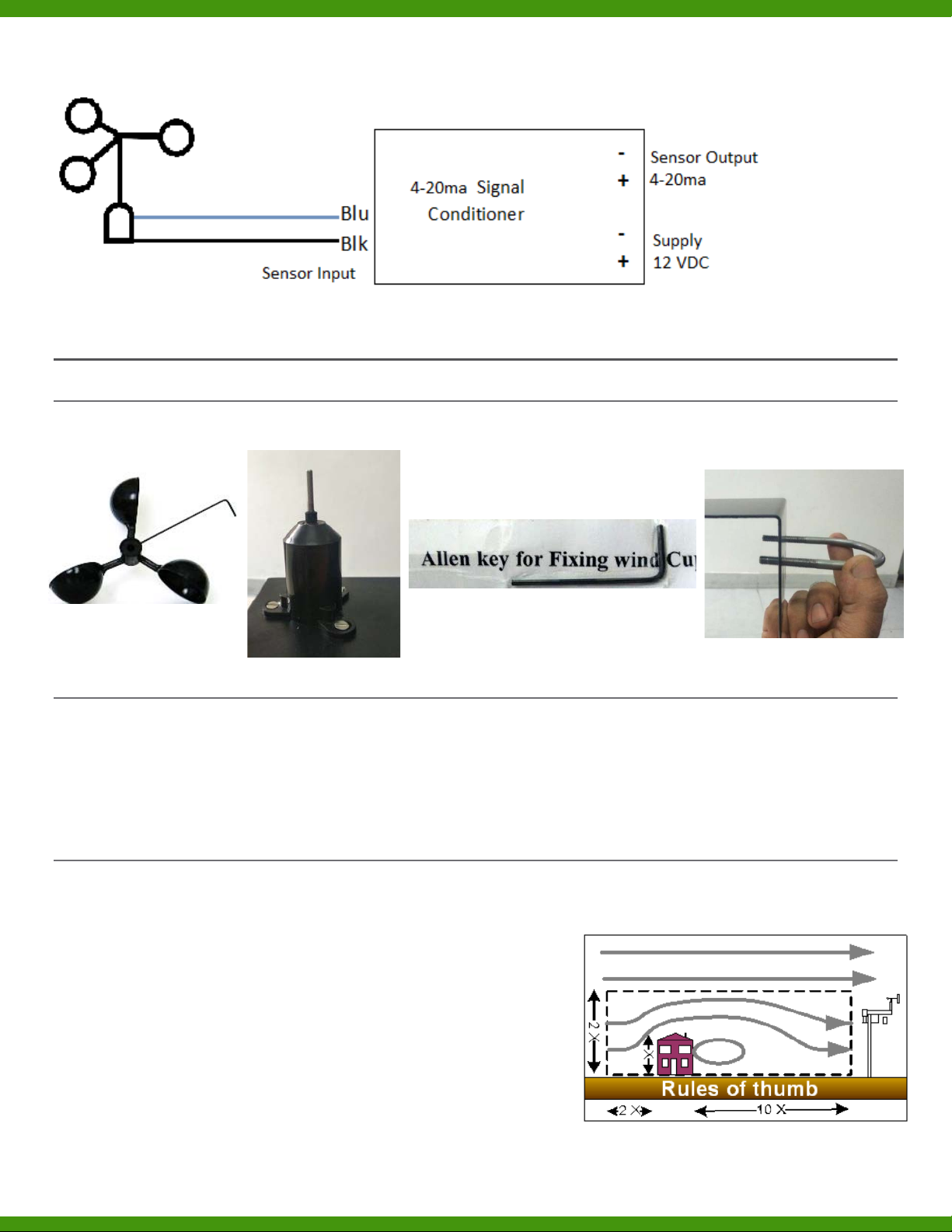
I/O Specifications for 4-20ma Sensor Output
INSTALLATION
Guidelines
The wind speed sensor comes in three different parts. We have the sensor body, the anemometer cup wheel and an
Allen key to mount the cup wheel on the sensor body. There are different ways to mount the sensor.
Tools and Materials Needed
Please make sure you have all the necessary material as mentioned below:
‐ Wire cutters and stripper
‐ Multi meter
‐ Screwdriver
‐ Electrical tapes to cover the wire
‐ Cable ties
‐ Adjustable Wrench
‐ Allen wrench (Supplied with sensor)
Location Recommendation
In order to report accurate weather information, you must take care in deciding where to place your weather station.
The process of deciding how and where to install your weather station is called "Siting". Siting is the single most
important factor in ensuring accurate readings. In fact, siting influences
the accuracy of weather readings much more than the quality of the
weather instruments themselves.
When selecting your mounting system, take into consideration that you
will occasionally need to access the anemometer for preventive
maintenance. Use the following guidelines to determine the best
location for mounting the wind speed sensor
•Allow sufficient clearance for the wind sensor.
•Install the anemometer in a location where wind flow is

unobstructed by trees and nearby buildings.
•Rule of Thumb-Near a building, mount the sensors outside the zone of influence. Horizontally this extends
roughly twice the height of the building upstream and ten times downstream. Vertically it extends to about
twice the height of the structure
If the requirement is to measure the true local conditions
•Mount the sensor so that the wind cups are at least 7 feet (2.1 m) above obstructions such as trees or buildings
that may obstruct wind flow
•Mount the sensor as the highest object for 50 feet in all directions.
Mounting
The Anemometer can be mounted using the three holes in the bottom mounting plates. This allows mounting on any flat
LEVEL surface.
Caution:
To prevent damaging the wind cups properly mount the sensor/bracket combination on the mast before fitting the wind
cup-unit whenever possible.
Note: Do not lubricate the force bearings
Orientation: The Anemometer should be mounted with its axis as close to vertical as possible to provide for the best
measurement of horizontal wind movement
Steps for Mounting:
1. With the supplied U‐bolt, the sensor suite can be mounted on a pole or rod
2. While holding the mounting base of the sensor suite against the pole, place the two ends of the U‐bolt around
the pole and through the two holes in the C‐shaped bracket on the base.
3. Gently slide the wind cup assembly down onto the anemometer’s stainless‐steel shaft
4. Use the allen wrench provided to tighten the set screw slightly on the side of the wind cups.
NOTE: DO NOT PUT EXCESS PRESSURE ON THE ALLEN WRENCH AS THIS CAN DAMAGE THE SENSOR PERMANENTLY
5. Spin the wind cups. If they do not spin freely, loosen the set screw, then retighten the set screw.
6. Repeat above step until the wind cups spin freely
7. When the sensor is properly oriented, tighten the hex nuts with a wrench.

Local Testing: Spinning the anemometer cup assembly will produce a series of pulses. To verify sensor output, monitor
this signal with either a translator module, data logger or an ohmmeter.
Caution
Do not Open the sensor bottom. This can permanently damage the sensor
and void warranty.
Guidelines for Securing Cables
•To prevent fraying or cutting of cables, secure them so they will not whip about in the wind.
•Secure cable to a metal pole using cable ties or by wrapping tape around both the cables and the pole.
•Place clips or ties every 3' – 5' (1 – 1.6 m).
Example Installations

Calibration
•If using Modbus sensor then the Wind speed Sensor is factory calibrated.
•If using analog output senor then use the following info to calibrate:
oOutput: 0 ‐ 5 VDC (0 to 250 km/hr)
oWind Speed in km/hr = 50*Sensor Output voltage (in Volt)
oOutput: 4‐20mA (0 to 250 km/hr)
oWind Speed in km/hr = 15.625*(Output in mA ‐ 4)
If the cable length is insufficient for the installation, additional cable can be added to the existing cable. If this is done, an
accuracy de‐rating factor must be added to the overall wind speed accuracy of this sensor.
It is highly recommended that the calibration be checked annually
Logger Connections
•For ANALOG output connections (Voltage or Current) , please search for ‘Installation Guide – Analog
Sensors’ on: https://trackso.in/trackso‐installation‐manuals/
•For MODBUS output connections, please search for ‘Installation Guide – MODBUS Sensors’ on:
https://trackso.in/trackso‐installation‐manuals/
Sensor Maintenance
•Maintenance includes inspection of mechanical operation and cleaning.
•Rotate wind cup assembly; look for smooth rotation and a gradual stop. If the cup wheel or the vane is not
rotating smoothly or it creates detectable noise, the bearings must be replaced
•Inspect mounting hardware for secure fasteners; mounting pipe must be vertical.
•Replace any loose or corroded fasteners.
•Inspect the cable and connections.
•It is recommended to check the ball bearings of the anemometer every year. If the cup wheel is not rotating
smoothly or it creates detectable noise, the bearings/sensors must be replaced.
•Clean any accumulation of dirt, dust, or bird droppings that may affect proper rotation of the wind speed sensor.
Use only soapy water and a soft cloth. Never use solvents or abrasive cleansers. Do not immerse the
anemometer in water.

Troubleshooting
.
Situation
Comments
If wind speed seems low
•A stiff bearing on the wind cups shaft‐ Use an Allen wrench to loosen the setscrew on
the side of the wind cups. Remove the wind cups, and also clean the exposed portion of
the shaft with a damp cloth or cotton swab. After tightening the setscrew, check to
make sure that the wind cups spin freely. If they do not, the bearings may be worn and
need factory repair.
•If all of the potential causes of zero wind speed listed above can be ruled out then it is
highly probable that the recorded wind speeds are essentially correct but anemometer
exposure is suboptimal. Get the anemometer up high and do so in as open a space as is
available.
High wind speed spikes
•Moisture getting into the PCB, sockets into which the anemometer cable is plugged.
•
Earth/ground issues where a ground loop is the culprit.
No Wind speed
detected
•Loss of supply voltage. Check +12 supply & connecting cables
•Faulty detector. Replace detector

Disclaimer
This sensor is a low‐cost alternative to the Class 1/Class 2 sensors of the same type. Since this sensor fall under no class,
there will be some variation in the real vs. expected values. If you wish to minimise the error/deviation in output values,
we recommend that you purchase Class 1/Class 2 sensor.
Please note this product is not manufactured by TrackSo, but sold by TrackSo, warranties are only to the limits extended
by the original manufacturer.
The document is compiled only to help our customer learn about the product and install it with minimum hassles. We do
not manufacture the product mentioned in this document or claim any part of it. Any information or services in this
document does not constitute any endorsement or recommendation of such products or services by us. We do not
warrant that the information contained in this document will be uninterrupted or error free, or that defects will be
corrected. We will not be liable to you or to any other person for any direct, indirect, incidental, punitive or
consequential loss, damage, cost or expense of any kind whatsoever from out of your usage of this document or the
information provided therein.
Warranty
Applicable Warranty Term & Conditions is available on ‐ https://trackso.in/warranty/
Repair ‐ For all returns for repair or warranty claims, the customer must fill out a “Service Form”. The form is available
from our website at https://trackso.in/service‐form/. A completed form must be submitted online. TrackSo is unable to
process any returns for repair or warranty until this form is received. If the form is not received within three days of
product receipt or is incomplete, the product will be returned to the customer at the customer’s expense.

FREE SPIRITS GREEN LABS PVT. LTD.
WZ 49, 1ST Floor, Budella, Vikas Puri, New Delhi ‐ 110018
GST: 07AACCF3845R1Z3
Sales: sales@trackso.in , Support: [email protected]
4000+
UNITS MONITORED Inverters, Sensors, Meters, Water Pumps
2000+
SOLAR SITES Rooftop & Commercial, Solar Water Pumps, Zero Export systems
Monitoring Sites
Table of contents
Popular Inverter manuals by other brands

Lenze
Lenze L-force 8400 Series Reference manual

LG
LG LG340N1C-A5 installation manual

Huawei
Huawei SU2000L-CN quick guide

Everpower Electronics
Everpower Electronics SD700 Programming and Software Manual

BWT
BWT AQA blue Assembly, Commissioning, Operation and Maintenance Manual

Deye
Deye SUN-10K-SG04LP3-EU Operation guide


SILENCE
SILENCE NOMAD user manual

Sunleaf
Sunleaf 3000TL Installation and operator's manual

Technaxx
Technaxx TX-203 user manual

SMA
SMA SUNNY HIGHPOWER PEAK3 Quick reference guide

Northern Lights
Northern Lights OM844W3 Operator's manual

Donauer
Donauer High Efficiency 3.0 Installation and operating instructions