4
(Optional) Installing the RS485 Communications Cable
3.5
When laying out communications
cables, separate them from power
cables to avoid strong signal
interference sources.
Ensure that the exposed core wire is
totally inserted into the cable hole and
connected securely.
RS485B, RS485 differential
signal
RS485A, RS485 differential
signal+
RS485B, RS485 differential
signal
RS485A, RS485 differential
signal+
Negative of the 12 V power
supply (reserved, power ≤ 3 W)
Positive of the 12 V power
supply (reserved, power ≤ 3 W)
Grounding the shield layer
If only one signal cable needs to
be connected, block the unused
cable hole on the seal using a
cap and tighten the cable gland.
If two signal cables are required,
ensure that they have the same
outer diameter.
4Verifying the Installation 5Powering On the System
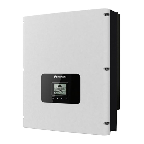
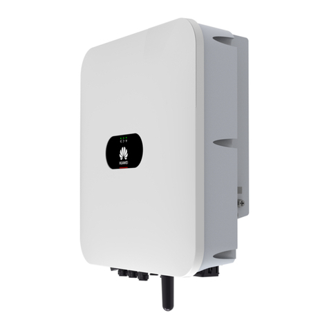
The SUN2000L is installed correctly, securely, and reliably.
antenna or 4G module is installed correctly, securely,
and reliably.
Cables are routed properly as required by the customer.
Cable ties are secured evenly and no burr exists.
The ground cable is connected correctly, securely, and reliably.
The DC switch and all the switches connecting to the
SUN2000L are OFF.
The AC output power cable, DC input power cable, and signal
cable are connected correctly, securely, and reliably.
Unused terminals and ports are locked by watertight caps.
The installation space is proper, and the installation
environment is clean and tidy, without foreign matter.
Before turning on the AC switch between the SUN2000L and the
power grid, check that the AC voltage on the power grid side of the
AC switch is within the specified range.
1. Turn on the AC switch between the SUN2000L and the power grid.
2. Turn on the DC switch between the PV string and the SUN2000L if there
is any.
3. Turn on the DC switch at the bottom of the SUN2000L.
4. Perform quick setting over the app by referring to the SUN2000L App
Quick Guide.
5. (Optional) Measure the temperatures at the joints between the DC
terminals and the connectors using a point-test thermometer.
6. Observe the LEDs to check the SUN2000L operating status.
Huawei Technologies Co., Ltd.
Huawei Industrial Base, Bantian, Longgang
Shenzhen 518129 People's Republic of China
solar.huawei.com
Status (Blinking at Long
Intervals: On for 1s and then
Off for 1s; Blinking at Short
Intervals: On for 0.2s and then
Off for 0.2s)
The SUN2000L is
exporting
Blinking green
at long intervals
The DC is on and the AC is off.
Blinking green
at long intervals
The DC is off and the AC is on.
Blinking green
at long intervals
Blinking green
at long intervals
The DC is on and the AC is on.
The SUN2000L is not exporting
power to the power grid.
The DC is off and the AC is off
or the SUN2000L is in low
power consumption mode.
Blinking green at short intervals
The SUN2000L is in
communication.
Blinking green at long intervals
The SUN2000L has connected
to the mobile phone.
communication
LED1 LED2
LED3
Blinking: The period is 2s. The LED is on for
0.1s, then off for 0.1s, then on for 0.1s, and
finally off for 1.7s.
No service is provided or the service
is limited.
Blinking: The period is 2s. The LED is on for
0.1s and then off for 1.9s.
The SUN2000L has connected to the
network.
The SUN2000L is in communication.
7. If a 4G module is installed, wait for about 15 seconds for dialup after the
inverter is powered on. Then observe the LED indicator on the 4G
module to check the module status.
Under normal operation conditions of the SUN2000L, the temperature
rise at DC connectors should remain below 40°C at all time.
Service Contact Information
The United
States and
Canada
mea_inverter_support@huawei.com
