Trackunit ME500-X User manual
ME500-X
Trackunit ME500-X, Technical Manual v.1.1, January
2016 Page 1
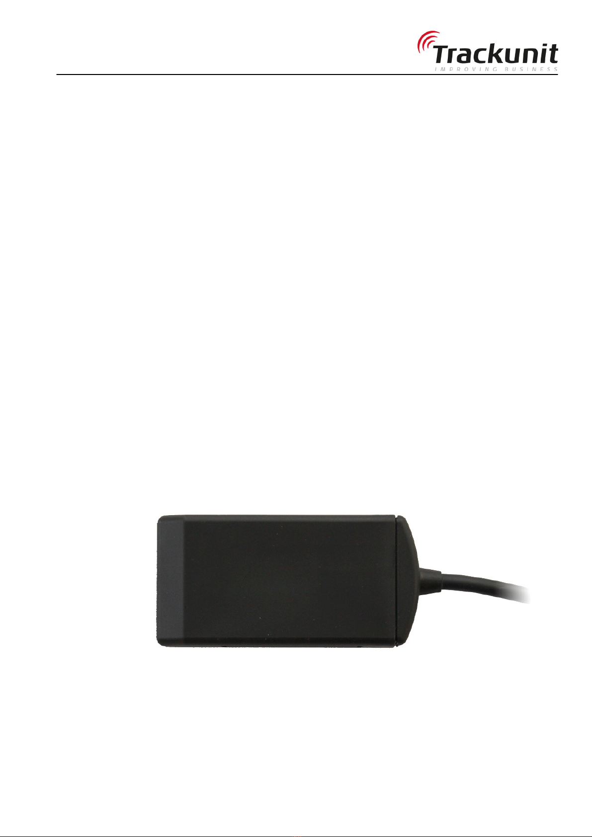
ME500-X
Technical Manual
Version 1.1, January 2016

ME500-X
Trackunit ME500-X, Technical Manual v.1.1, January 2016 Page 2
Content
Content.......................................................................................................... 2
Related Information..........................................................................................................5
Safety first...................................................................................................... 5
Simple Guidelines ............................................................................................................5
Detailed Safety Information............................................................................ 6
Exposure to Radio Frequency Signals .............................................................................6
Delivered standard content............................................................................ 9
Installing the unit.......................................................................................... 10
Practical installation advice ............................................................................................10
Connections ...................................................................................................................10
Power supply ..............................................................................................................11
Digital inputs ...............................................................................................................11
Digital output...............................................................................................................11
Motion/acceleration sensor.........................................................................................11
1-Wire input ................................................................................................................11
Functionality check ...................................................................................... 12
LED ................................................................................................................................12
Status SMS Commands .................................................................................................13
Installation of the digital output .................................................................... 15
SMS commands for output control .................................................................................16
Safety precautions..........................................................................................................16
Warranty...................................................................................................... 17
Technical Assistance ................................................................................... 17
Minimum Information Required for Technical Assistance...............................................17
Return Merchandise Authorization - RMA ......................................................................18
Specifications .............................................................................................. 19
Product specifications ....................................................................................................19
Connections:...............................................................................................................19
Temperature range:....................................................................................................19
GSM/GPRS-specifications:.........................................................................................19
Mechanical specifications ...........................................................................................21
Approvals and certificates............................................................................ 21

ME500-X
Trackunit ME500-X, Technical Manual v.1.1, January 2016 Page 3
Corporate Office
M-Tec Trackunit A/S
Industrivej 10
9490 Pandrup
Denmark.
www.trackunit.com
Copyright and Trademarks
© 1998-2016, M-Tec Trackunit A/S. All rights reserved.
M-Tec, the red M hyphen TEC logo, Trackunit, Trackunit logo
and Trackunit are trademarks of M-Tec Trackunit A/S,
registered in the United States and in other countries. All other
trademarks are the property of their respective owners.
Release Notice
This document is release 1.X of the ME500-X, Technical
Manual.
THIS MANUAL IS INTENDED FOR USE BY SYSTEM
INTEGRATORS, SERVICE PROVIDERS AND APPLICATION
DEVELOPERS (COLLECTIVELY, “RESELLERS”). IT IS NOT
INTENDED FOR END-USERS OF THE ME500-X. ANY END-
USER DOCUMENTATION IS TO BE PREPARED AND
FURNISHED BY THE RESELLERS.
The following Product Limited Warranty gives Resellers
specific legal rights. You may have others, which vary from
state/jurisdiction to state/jurisdiction.
Product Limited Warranty
Subject to the terms and conditions set forth herein, M-Tec
Trackunit A/S (“Trackunit”) makes the following warranty only
to its Resellers who purchase the ME500-X hardware product
(“Product”) directly from Trackunit: for a period of one (1)
year from the date of shipment from Trackunit, the Product will
substantially conform to Trackunit’s standard published
specifications for the Product and the Product hardware will be
substantially free from defects in materials and workmanship.
The foregoing warranty shall not apply to embedded
software/firmware components.
THIS PRODUCT LIMITED ARRANTY IS PROVIDED TO
RESELLERS AND TO RESELLERS ONLY. RESELLER IS
SOLELY RESPONSIBLE FOR ANY AND ALL ARRANTIES
MADE TO ITS CUSTOMERS, AND TRACKUNIT MAKES NO
ARRANTIES, EXPRESS OR IMPLIED, AND SHALL HAVE
NO OBLIGATIONS OR LIABILITY TO RESELLER’S
CUSTOMERS OR END-USERS OF THE PRODUCT.
RESELLER SHALL NOT
MAKE ANY REPRESENTATIONS OR ARRANTIES ON
TRACKUNIT’S BEHALF, AND SHALL FULLY INDEMNIFY,
DEFEND AND HOLD TRACKUNIT HARMLESS FROM ANY
BREACH OF THE FOREGOING. IF RESELLER DISTRIBUTES
PRODUCT TO END-USER CUSTOMERS, RESELLER SHALL
BE SOLELY RESPONSIBLE FOR PREPARING AND
PROVIDING PRODUCT ARRANTIES AND PRODUCT
LITERATURE TO END-USERS.
Warranty Remedies
If the Product fails during the warranty period for reasons
covered by this Product Limited Warranty and Reseller notifies
Trackunit of such failure during the warranty period, Trackunit
at is option will repair OR replace the nonconforming Product,
OR refund the purchase price paid by Reseller for the Product,
provided that Reseller returns the Product to Trackunit in
accordance with Trackunit’s standard return material
authorization procedures or as otherwise instructed by
Trackunit.
Warranty Exclusions and Disclaimers
The foregoing Product Limited Warranty shall only apply in the
event and to the extent that (i) the Product is properly and
correctly installed, configured, interfaced, maintained, stored
and operated in accordance with Trackunit’s specifications, and
(ii) the Product is not modified or misused. This Product
Limited Warranty shall not apply to, and Trackunit shall not be
responsible for, defects or performance problems resulting from:
(a) the combination or utilization of the Product with hardware
or software products, information, data, systems, interfaces,
services or devices not made, supplied or specified by
Trackunit; (b) the operation of the Product under any
specifications other than, or in addition to, Trackunit’s standard
published specifications for the Product; (c) the unauthorized
installation, modification or use of the Product; (d) damage
caused by: accident, lightning or other electrical discharge,
water immersion or spray, or exposure to environmental
conditions for which the Product is not intended; or (e) normal
wear and tear on consumable parts, including by way of
example and without limitation, batteries.
TRACKUNIT DOES NOT ARRANT OR GUARANTEE THE
RESULTS OBTAINED THROUGH THE USE OF THE
PRODUCT. THE FOREGOING TERMS OF THE PRODUCT
LIMITED ARRANTY STATE TRACKUNIT’S ENTIRE
LIABILITY, AND RESELLER’S EXCLUSIVE REMEDIES,
RELATING TO THE USE AND PERFORMANCE OF THE
PRODUCT EXCEPT AS OTHER ISE EXPRESSLY PROVIDED
FOR IN THIS PRODUCT LIMITED ARRANTY, THE
PRODUCT, ACCOMPANYING DOCUMENTATION AND
MATERIALS, AND/OR ANY EMBEDDED
SOFT ARE/FIRM ARE AND UPDATES THERETO ARE
PROVIDED “AS-IS” AND ITHOUT EXPRESS OR IMPLIED
ARRANTIES OF ANY KIND, BY EITHER TRACKUNIT OR
ANYONE HO HAS BEEN INVOLVED IN ITS CREATION,
PRODUCTION, INSTALLATION OR DISTRIBUTION,
INCLUDING, BUT NOT LIMITED TO, THE IMPLIED
ARRANTIES OF MERCHANTABILITY AND FITNESS FOR
A PARTICULAR PURPOSE, TITLE AND
NONINFRINGEMENT. THE STATED EXPRESS
ARRANTIES ARE IN LIEU OF ALL OBLIGATIONS OR
LIABILITIES ON THE PART OF TRACKUNIT ARISING OUT
OF, OR IN CONNECTION ITH, THE PRODUCT.
ITHOUT LIMITING THE GENERALITY OF THE
FOREGOING:
TRACKUNIT IS NOT RESPONSIBLE FOR THE OPERATION
OR FAILURE OF OPERATION OF GPS SATELLITES OR
IRELESS SERVICE OR THE AVAILABILITY OF GPS
SATELLITE SIGNALS OR IRELESS SERVICE. THE
PRODUCT MAY CONTAIN TECHNOLOGY THAT IS NOT
FAULT TOLERANT AND IS NOT DESIGNED,
MANUFACTURED OR INTENDED FOR USE IN
ENVIRONMENTS OR APPLICATIONS IN HICH THE
FAILURE OF THE PRODUCT OULD LEAD TO DEATH,
PERSONAL INJURY OR SEVERE PHYSICAL OR
ENVIRONMENTAL DAMAGE OR SEVERE FINANCIAL LOSS.
ANY USE OR DISTRIBUTION BY RESELLER OR ITS
CUSTOMERS IN CONNECTION ITH ANY SUCH
ENVIRONMENT OR APPLICATION SHALL BE AT
RESELLER’S AND ITS CUSTOMERS’ SOLE RISK, AND

ME500-X
Trackunit ME500-X, Technical Manual v.1.1, January 2016 Page 4
TRACKUNIT SHALL HAVE NO LIABILITY HATSOEVER IN
CONNECTION THERE ITH. RESELLER SHALL INDEMNIFY
AND HOLD TRACKUNIT AND ITS SUPPLIERS HARMLESS
FROM ANY CLAIM BROUGHT AGAINST TRACKUNIT
HICH ARISES FROM RESELLER’S USE OR
DISTRIBUTION OF THE PRODUCT IN CONNECTION ITH
SUCH ENVIVRONMENTS OR APPLICATIONS. SOME
STATES AND JURISDICTIONS DO NOT ALLO
LIMITATIONS ON DURATION OR THE EXCLUSION OF AN
IMPLIED ARRANTY, SO CERTAIN OF THE ABOVE
LIMITATIONS MAY NOT APPLY TO EVERY RESELLER.
Embedded Software/Firmware
The Product and associated tools, if any, may contain embedded
software/firmware, which is licensed, not sold, and is only for
use within the Product as an integral part thereof. Such
embedded software/firmware (which includes all updates
thereto) contains valuable trade secrets and is proprietary to
Trackunit and its suppliers. To the greatest extent permitted by
law, such embedded software/firmware may not be modified,
copied, disassembled, decompiled or reverse engineered.
Trackunit reserves all other rights.
Limitation of Liability
TRACKUNIT’S ENTIRE LIABILITY REGARDING THE
PRODUCT SHALL BE LIMITED TO THE AMOUNT
ACTUALLY PAID BY RESELLER FOR THE PRODUCT. TO
THE MAXIMUM EXTENT PERMITTED BY APPLICABLE LA ,
IN NO EVENT SHALL TRACKUNIT OR ITS SUPPLIERS BE
LIABLE FOR ANY INDIRECT, SPECIAL, INCIDENTAL OR
CONSEQUENTIAL DAMAGES HATSOEVER UNDER ANY
CIRCUMSTANCE OR LEGAL THEORY RELATING IN ANY
AY TO THE PRODUCTS, ACCOMPANYING
DOCUMENTATION AND MATERIALS, AND ANY
EMBEDDED SOFT ARE/FIRM ARE AND UPDATES
THERETO (INCLUDING, ITHOUT LIMITATION,
DAMAGES FOR LOSS OF BUSINESS PROFITS,
BUSINESS INTERRUPTION, LOSS OF DATA OR ANY
OTHER PECUNIARY LOSS), REGARDLESS OF HETHER
TRACKUNIT HAS BEEN ADVISED OF THE POSSIBILITY OF
ANY SUCH LOSS AND REGARDLESS OF THE COURSE OF
DEALING BET EEN TRACKUNIT AND RESELLER.
BECAUSE SOME STATES AND JURISDICTIONS DO NOT
ALLO THE EXCLUSION OR LIMITATION OF LIABILITY
FOR CONSEQUENTIAL OR INCIDENTAL DAMAGES, THE
ABOVE LIMITATION MAY NOT APPLY TO EVERY
RESELLER.
Notices
Class B Statement – Notice to Users. This equipment has been
tested and found to comply with the limits for a Class B digital
device, pursuant to Part 15 of the FCC rules. These limits are
designed to provide reasonable protection against harmful
interference in a residential installation. This equipment
generates, uses, and can radiate radio frequency energy and, if
not installed and used in accordance with the instructions, may
cause harmful interference to radio communication. However,
there is no guarantee that interference will not occur in a
particular installation. If this equipment does cause harmful
interference to radio or television reception, which can be
determined by turning the equipment off and on, the user is
encouraged to try to correct the interference by one or more of
the following measures:
– Reorient or relocate the receiving antenna.
– Increase the separation between the equipment and the
receiver.
– Consult the dealer or an experienced radio/TV technician for
help.
Changes and modifications not expressly approved by the
manufacturer or registrant of this equipment can void your
authority to operate this equipment under Federal
Communications Commission rules.
Regulatory Approvals
CE
The ME500-X product comply with the essential requirements
of the R&TTE Directive 1999/5/EC as stated by the EC
Declaration of Conformity (CE 0682). The ME500-X product
comply with the European Telecommunications Standards
Institute Specifications EN 301 489-1, EN 301 489-7 (EMC for
GSM 900MHz and DCS 1800MHz for Radio Equipment and
Systems).
EC/ International
The ME500-X product comply with the essential requirements
of the Automotive directive 2004/104/EC clause 6.5, 6.6, 6.8
and 6.9, UN regulative ECE R10 EMC rev4.
The ME500-X product comply with the essential requirements
of the Directive 2003/37/EEC and Directive 2006/42/EEC.
The ME500-X product comply with the international standards
ISO-13309, ISO-13766 and EN ISO-14982, for tractors, forest
and agricultural machinery, moving machinery and construction
machinery.
The ME500-X product complies with the essential and
environmental requirements of the Interoperability of trans-
European conventional rail system 2001/16/EC and 2004/50/EC
directives according to ISO 50121-3-2 and DIN EN 50125-1,
when used as intended on rolling stock and transportation.
The ME500-X complies with the essential requirements of the
2011/65/EC directive on the restriction of the use of certain
hazardous substances in electrical and electronic equipment.
FCC
The ME500-X product comply with the FCC Part 15, Part 22,
Part 24, and the Industry Canada requirements RSS-GEN, RSS-
102, RSS-132, RSS-133.
The ME500-X product comply with Part 15 of the FCC rules.
Operation is subject to the following two conditions: (1) This
device may not cause harmful interference, and (2) This device
must accept any interference received, including interference
that may cause undesired operation.
For fixed mounted operations the ME500-X must be installed to
provide a separation distance of at least 20 cm from all persons.
ME500-X:
FCC ID: ZMF-ME500
IC-ID: 9746A-ME500

ME500-X
Trackunit ME500-X, Technical Manual v.1.1, January
2016 Page 5
Introduction
This document contains the installation guide for the (GSM/GNSS) product type series
ME500-X units. This manual is intended for use by system integrators, service providers
and application developers (collectively, “Resellers”). It is not intended for end-users of the
ME500-X. Any end-user documentation is to be prepared and furnished by the Resellers.
This manual covers the ME500-X with 60.010 and later firmware operating on 2.5G bands
850 MHz, 900 MHz, 1800 MHz and 1900 MHz Global System for Mobile communication
(GSM) networks.
Data and Event Reporting support is by Short Message Service (SMS), General Packet
Radio Service (GPRS), or both.
This manual describes how to set up, configure, install, operate, and troubleshoot the
product. Even if you have used other GSM or Global Positioning System (GPS) products
before, Trackunit recommends that you spend some time reading this manual to learn
about the special features of this product.
Trackunit assumes that you are familiar with Microsoft Windows.
Related Information
The Trackunit web site is found at www.trackunit.com. This site links to the fleet
management system from M-Tec Trackunit A/S called Trackunit Manager. ME500-X
devices are integrated to Trackunit but can also be used together with third part system
providers.
Safety first
Simple Guidelines
Please follow these guidelines when configuring, using or recycling the ME500-X. Violating
these guidelines may be dangerous, illegal or otherwise detrimental. Further detailed
information is provided in this manual.
Do Not Operate Where Prohibited
Do not allow the ME500-X unit to operate wherever wireless phone use is prohibited or
when doing so may cause interference or danger. The ME500-X cannot be turned off after
installation, so any vehicle, moving machinery, construction machinery using ME500-X etc.
must not enter areas where it is prohibited to operate wireless phones as the device
periodically turns on the transmitter in a short period of time to perform tracking reporting.
Examples include but are not limited to operation in hospitals, aircrafts, near blasting sites
or wherever operation can cause interference.
Interference
Table of contents
Other Trackunit Automobile Accessories manuals

Popular Automobile Accessories manuals by other brands


ULTIMATE SPEED
ULTIMATE SPEED 279746 Assembly and Safety Advice

SSV Works
SSV Works DF-F65 manual

ULTIMATE SPEED
ULTIMATE SPEED CARBON Assembly and Safety Advice

Witter
Witter F174 Fitting instructions

WeatherTech
WeatherTech No-Drill installation instructions

TAUBENREUTHER
TAUBENREUTHER 1-336050 Installation instruction