Tractel Group jockey Manual

jockey®&J5
Lifting and pulling machines
models
JOCKEY
J5
equipment
in accordance
with CE directives
operating
and
maintenance
instructions
109325-03 - ind 04 - 09/02
Anglia Handling Services Ltd
2
CONTENTS Page
General warning 3
Technical data 3
1. Description of equipment 4
2. Rigging arrangements 4
3. Installing the wire rope 5
4. Releasing and closing the jaws 6
5. Anchoring 6
6. Operation 6
7. Taking out of service and storage 7
8. Safety devices 7
9. Wire rope 8
10. Mantenance instructions 8
11. Warnings against hazardous operations 9
12. Troubleshooting 9
13. Health and safety at work 9
Always concered to improve the quality of its
products, theTRACTEL Group reserves the right
to modify the specifications of the equipment
described in this manual.
The companies of the TRACTEL Group and their
agents or distributors will supply on request
descriptive documentation on the full range of
TRACTEL products : lifting and pulling machines,
permanent and temporary access equipment,
safety devices, electronic load indicators,
accessories such as pulley blocks, hooks, slings,
ground anchors, etc.
1. Anchor hook
2. Forward operating lever
3. Reverse operating lever
4. Rope release catch
5. Side buttons
6. Rope guide
7. Wire rope
8. Operating handle
9. Anchor sling
8
6
7
9
1 4 2
A B
3
8
6
7
9
1 4
23
5
ORIGINAL MANUAL
The TRACTEL network is able to
supply an after-sales and regular
maintenance service.
Anglia Handling Services Ltd

3
1- Before using the machine, it is essential for safe and correct operation of the equipment that
this manual be read and fully understood and that all the instructions be followed. This manual
should be made available to every operator. Extra copies of this manual will be supplied on
request.
2- The JOCKEY machine allows the operator to carry out work with complete safety. Ensure that
the machine is only handed over for use or rigging to an operator who is trained to operate it in
a responsible manner
3- Never use a machine which is not in good working condition. Replace any worn or damaged wire
rope. A continous monitoring of the condition of the machine, its wire rope and anchor sling is an
important safety consideration.
4- The manufacturer declines any responsibility for the consequences of dismantling or altering the
machine by any unauthorised person. Specially excluded is the replacement of original parts by
parts of another manufacturer.
5- The models covered by this manual must not be used under any circumstances for lifting people.
6- Moreover, these models are designed for manual operation and must not be motorised.
TRACTEL has designed special motorised models (TU-16H and TU-32H).
7- Never apply or attempt to apply to the machine a load or effort greater than the working load limit.
8- JOCKEY machines are not designed for use in explosive atmospheres.
9- IMPORTANT : If the equipment described in this manual is supplied to an employed person,
check and ensure that you meet your obligations with respect to the safety at work regulations,
particularly relating to inspection and tests before operation (See section 13 on page 9).
LIFTING PEOPLE AND SPECIAL APPLICATIONS
For further information on equipment for lifting people, and for any special application, please refer to
TRACTEL TECHNICAL DATA
MODELS jockey jockey J5
Working load limit kg 300 500
Weight
machine kg 1.750 3.750
operating handle kg 0.270 0.350
standard length of wire rope 10m/20m kg 1.0 / - 1.9 / 3.7
Total weight of standard equipment kg 3.0 / - 6.0 / 7.8
Machine dimensions
length mm 320 370
height mm 200 215
width mm 40 55
operating handle mm 400 500
JOCKEY wire rope
diameter mm 4.72 6.5
guaranteed breaking strain* kg 1800 3100
weight per meter kg 0.09 0.185
Rope travel (foward/reverse)** mm 28 / 32 24 / 34
*Including end fittings of the wire rope.
** One complete cycle of the operating lever with working load limit.
Anglia Handling Services Ltd
4
1. DESCRIPTION OF EQUIPMENT
The JOCKEY machine is a hand-operated lifting
and pulling machine. It is versatile, portable and
multipurpose, not only for pulling and lifting but
also for lowering, tensioning and guying.
The originality of the JOCKEY machine is the
principle of operating directly on the wire rope
which passes through the mechanism rather than
being reeled onto a drum of a hoist or conventional
winch. The pull is applied by means of two pairs of
self-energised jaws which exert a grip on the wire
rope in proportion to the load being lifted or pulled.
An operating handle fitted to either the forward or
the reverse lever transmits the effort to the jaw
mechanism to give forward or reverse movement
of the wire rope.
The machine is fitted with an anchor hook so that
it can be secured quickly to any suitable anchor
point.
The JOCKEY machines, intended for lifting and
pulling materials, are available in two models :
• Jockey, capacity 300 Kg
• Jockey J5, capacity 500 Kg
Jockey : the standard kit comprises a machine
with its operating handle, a 10 m length of special
Jockey wire rope fitted with a hook with safety
catch and two wire rope slings, one 1m in length
and the other 2 m in length. The equipment is
contained in a sturdy carton for carrying and
storing the kit. Other lengths of wire rope are
available on special order.
Jockey J5 : the J5 is available in two standard kits
comprising a machine with its operating handle
and with :
• either a 10m length of special wire rope fitted
with a hook with safety catch and two anchor
slings of 2m in length :
• or a 10m length of special wire rope fitted with a
hook with safety catch, two anchor slings of 2m in
length and pulley block allowing the capacity of the
machine to be doubled.
This manual together with a guarantee card are
supplied with each machine, as well as the CE
declaration of conformity.
IMPORTANT : JOCKEY wire rope has been
specially designed to meet the particular
requirments of the JOCKEY machines.
TRACTEL does not guarantee the safe
operation of JOCKEY machines used with wire
rope other than JOCKEY wire rope.
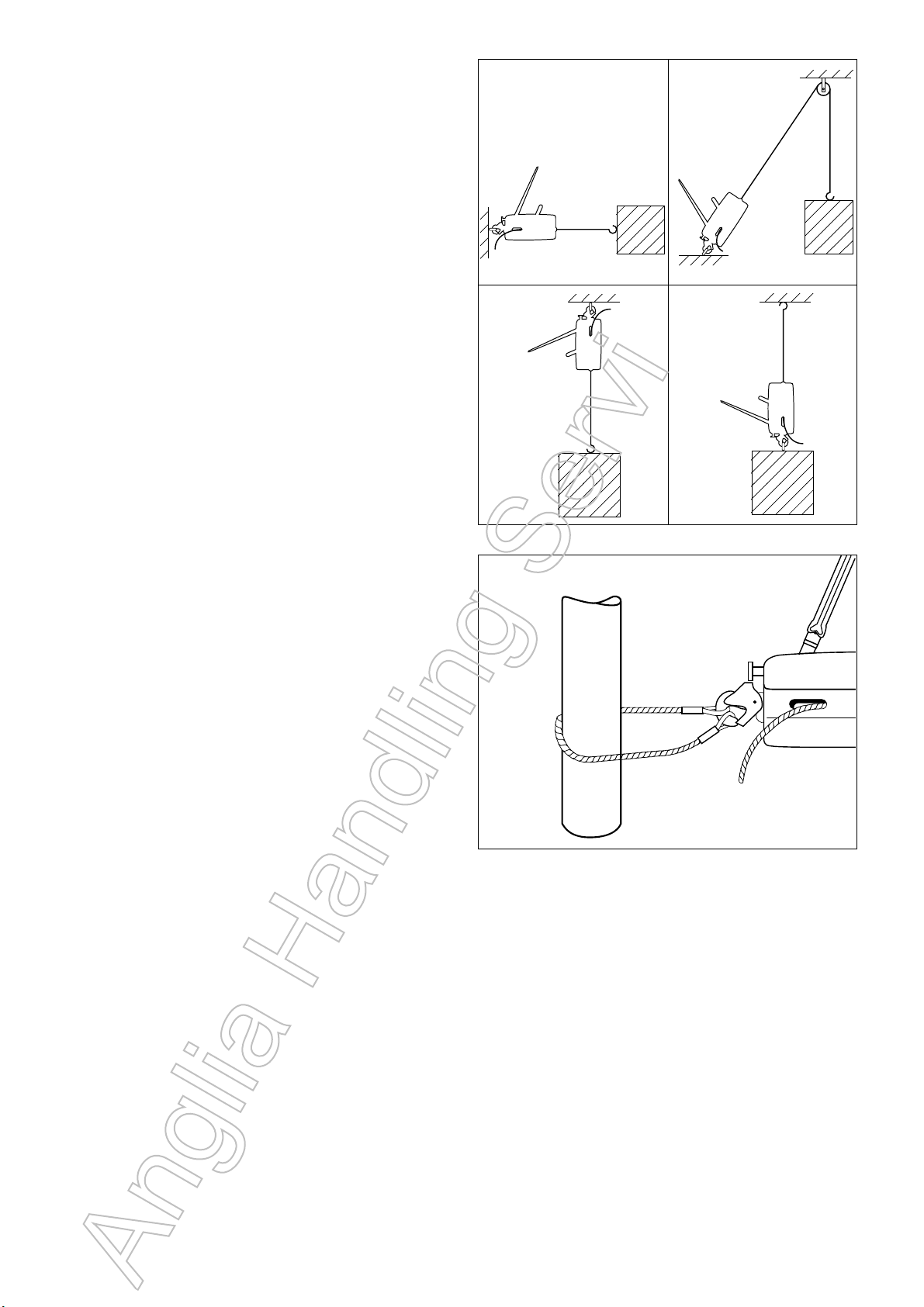
2. RIGGING ARRANGEMENTS
Various ways of rigging are shown in Figs. 2.1,
2.2, 2.3 and 2.4. Figs. 4 and 5 show particular
arrangements (one forbidden and the other
recommended).
The machine may be anchored to a fixed point
with the wire rope travelling towards the machine
(Figs. 2.1, 2.2, 2.3, or travel along the wire rope,
with the load, the wire rope itself anchored to a
fixed point (Fig. 2.4).
In example 2.2, the capacity of the pulley and the
anchor point should be greater than twice the load.
N.B. : Whatever the rigging arrangement, and if
the machine is anchored directly to a fixed point,
ensure that there are no obstructions around the
machine which could prevent the wire rope, the
machine and anchor from operating in a straight
line. It is therefore recommended to use a sling of
an appropriate capacity between the anchor point
Fig. 2.1 Fig. 2.2
Fig. 2.3
Fig. 3
Fig. 2.4
,
,
,
,
,
,
Anglia Handling Services Ltd
5
and the machine (Fig. 3).
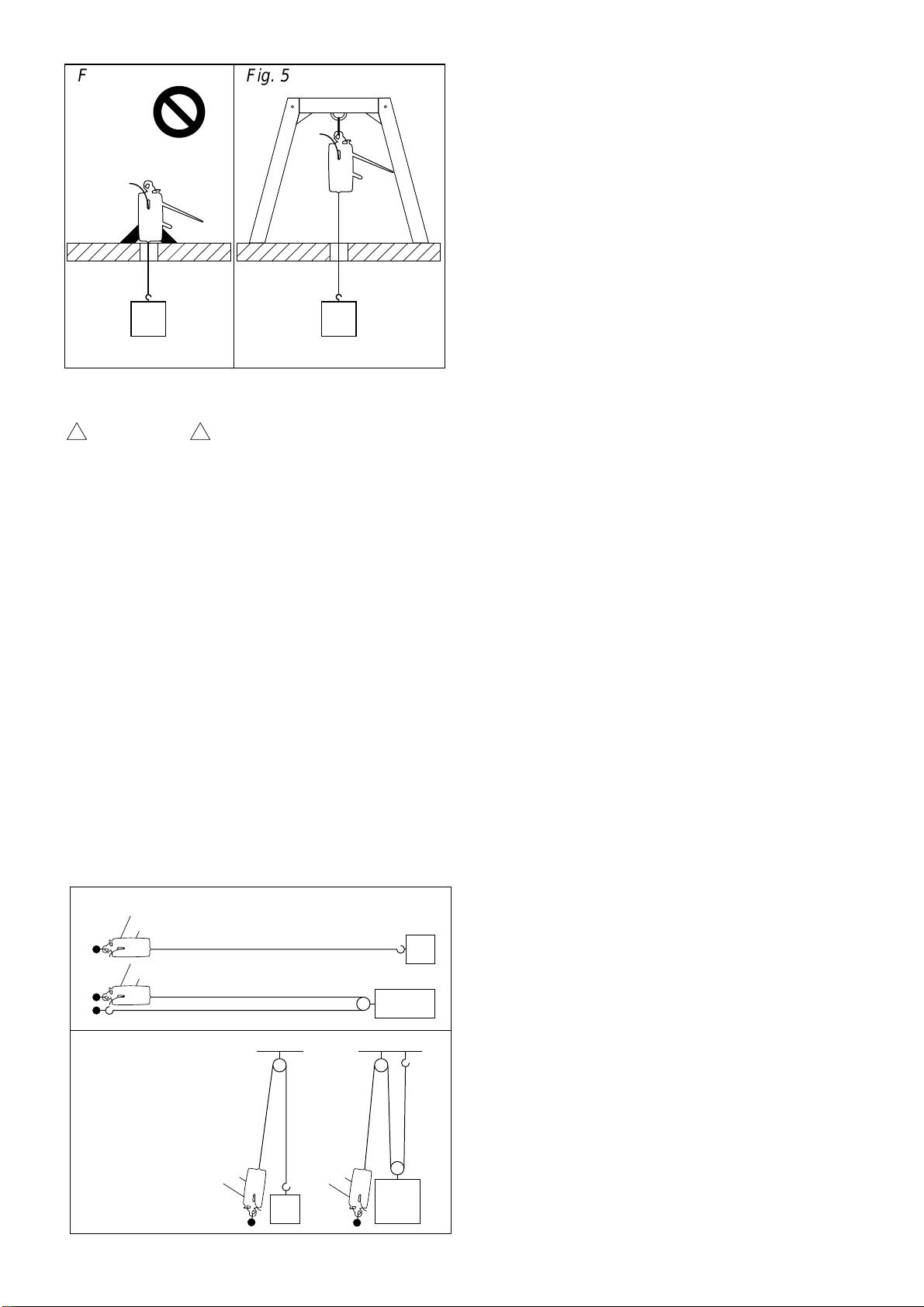
WARNING : Any rigging arrangement
which requires the calculation of the forces applied
should be checked by a competent engineer, with
special attention to the appropriate strength of the
fixed points used.
For work such as guiding the trunk in tree felling,
the operator should ensure that he is outside the
danger area by passing the wire rope around one
or more return pulleys.
The capacity of the machine may be inceased
considerably for the same effort by the operator by
using a pulley block. (See the examples set out in
Figs. 6.1 and 6.2). The increase in the capacity
shown is reduced depending on the efficiency of
the pulleys.
The diameter of the pulleys used should be equal
to at least 18 times the diameter of the wire rope.
(Refer to the applicable regulations).
For any rigging arrangement other than those
described in this manual, please consult
TRACTEL or a competent specialist engineer
before operating the machine.
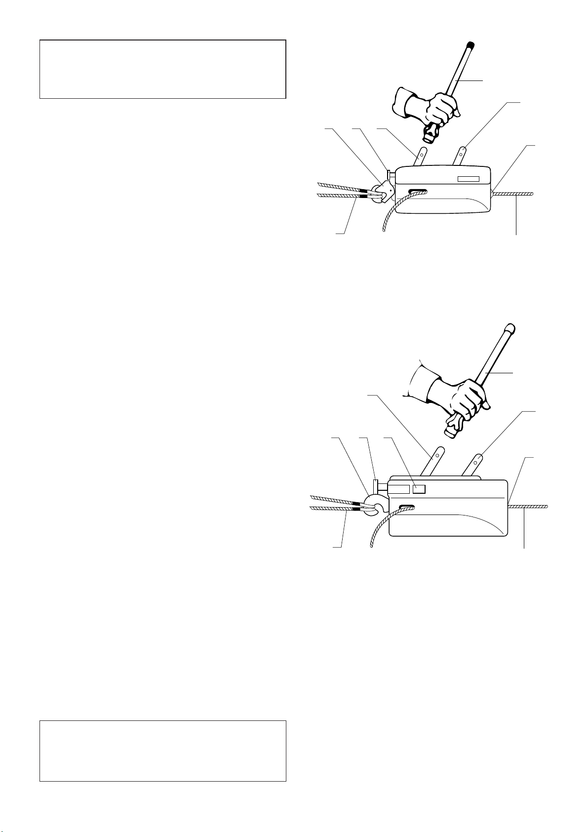
3. INSTALLING THE WIRE ROPE
N.B. : When handling the wire rope it is
recommended to protect the hands by using work
gloves.
If the wire rope is to be anchored to a high anchor
point, the wire rope should be anchored before
fitting the wire rope in the machine.
3.1. Jockey (green plastic casing).
1. Uncoil the wire rope in a straight line to prevent
loops or kinks.
2. Release the internal mechanism (See section 4 :
‘Releasing and closing the jaws’).
3. Insert the tapered end of the wire rope through
the rope guide E and push it through the
mechanism until it emerges at S (Fig. 7.2).
4. Pull the slack wire rope through the machine to
the point required.
5. Engage the jaws by operating the rope release
catch (See section 4 : ‘Releasing and closing
the jaws’).
6. Couple the two eyes of the sling which is around
the anchor point to the hook of the machine.
(See section 5 : ‘Anchoring’).
7. Fit the operating handle on the forward
operating lever and by moving it back and forth
the wire rope will be pulled through the
machine. The reverse operating lever allows the
user to slacken off tension or to lower the load.
After this procedure the machine is ready for
operation, providing the load is correctly anchored
to the machine or the wire rope (See section 5 :
‘Anchoring’ and section 2 : ‘Rigging arrangement’).
3.2. Jockey J5 (aluminium casing)
1. Uncoil the wire rope in a straight line to prevent
loops or kinks.
2. Release the internal mechanism (See section 4
: ‘Releasing and closing the jaws’).
3. Insert the tapered end of the wire rope through
the rope guide E and push it through the
mechanism until it emerges at S (Fig. 8.2).
4. Couple the two eyes of the sling which is around
the anchor point to the hook of the machine.
(See section 5 : ‘Anchoring’).
5. Pull the slack wire rope through the machine to
the point required.
6. Engage the jaws by operating the rope release
catch (See section 4 : ‘Releasing and closing
the jaws’).
!
!
Fig. 5Fig. 4
INTERDIT BON
1
1
2
2
Fig 6.1 - Traction
Fig 6.2 - Levage
1
1 1 1 1 1
1
1
1
1
12
2 2
2
1
Anglia Handling Services Ltd

6
7. Fit the operating handle on the forward
operating lever and by moving it back and forth
the wire rope will be pulled through the
machine. The reverse operating lever allows the
user to slacken off tension or to lower the load.
After this procedure the machine is ready for
operation, providing the load is correctly anchored to
the machine or the wire rope (See section 5 :
‘Anchoring’ and section 2 : ‘Rigging arrangements’).
4. RELEASING AND CLOSING THE JAWS
Each machine is fitted with a rope release catch
(item 4 in Fig. 1 on page 2) for releasing the jaw
mechanism and which should only be operated
when the machine is not under load.
4.1. Jockey
Releasing : Release the rope release catch by
pushing it against the machine lightly and
upwards. Then pull the catch outwards. (Fig. 7.1).
Closing : Push the rope release catch towards the
machine and then downwards, until it locks in
position. (Fig. 7.2).
4.2. Jockey J5
Releasing : Release the rope release catch by
pushing it against the machine and then pressing in
the two catches on either side of the machine.
Then pull the rope release catch outwards. (Fig. 8.1).
Closing : Push the rope release catch towards the
machine until it locks in position. (Fig. 8.2).
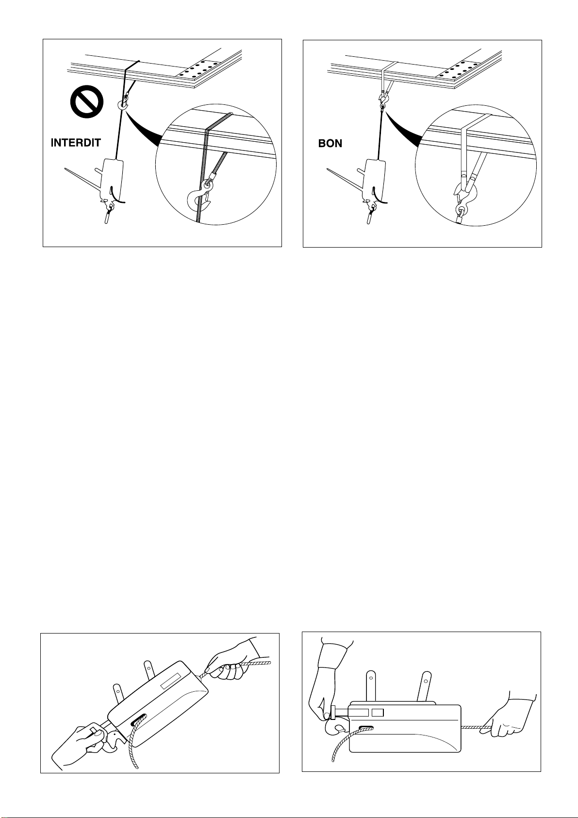
5. ANCHORING
Failure to anchor the JOCKEY machine
correctly runs the risk of a serious accident.
The user must always check, before operating
the machine, that the anchor point of the
machine and the wire rope are of sufficient
strength to take the load applied (lifting or
pulling).
It is recommended to anchor JOCKEY machines
to the fixed point or to the load using an
appropriate capacity sling. It is forbidden to use
the machine’s wire rope as a sling by passing it
around the load and hooking it back onto itself
(Fig. 9.1 : forbidden anchoring arrangement ; Fig.
9.2 correct anchoring arrangement).
Warning : It is essential for the safe
operation of the machine to ensure that, before
loading the machine, the anchor points (hooks) are
correctly secured, (with the safety catch correctly
located on the hook).
Pass one of the slings around the fixed point (tree,
beam, etc…)
Anchor the other sling to the load to be lifted or
pulled. Attach the two eyes of this sling to the wire
rope hook.
6. OPERATION
JOCKEY machines are very easy to use. Place the
operating handle on either the forward or reverse
operating lever and move the operating handle to
!
!
!
!
Fig. 7.1 Fig. 8.1
SS
Fig. 8.2
E
E
Fig. 7.2
Anglia Handling Services Ltd
and fro. The operating arc is variable for ease of
operation.
When operation stops, both jaws automatically grip
the wire rope and hold the load which is spread
equally between the jaws.
The to and fro operation of forward or reverse lever
gives continous movement of the load.
7. TAKING OUT OF SERVICE AND STORAGE
7.1. Jockey
When the work is completed take the load off the
machine before attempting to release the jaws. To
do this, operate the reverse operating lever until
there is no tension in the wire rope
Remove the sling and release the machine as
follows:
-release the mechanism by pushing the rope
release catch towards the machine and
upwards (Fig. 7.1).
-pull the wire rope out with one hand while
holding the machine by its rope release catch with
the other hand (Fig. 10).
Carefully coil the wire rope avoiding any loops or
kinks.
Only normal effort is required to operate the
Jockey. Do not force the operating handle;
otherwise the unit will be overloaded. Reduce the
load or use a pulley block to increase the capacity
of the unit.
7.2. Jockey J5
When the work is completed take the load off the
machine before attempting to release the jaws. To
do this, operate the reverse operating lever until
there is no tension in the wire rope
Remove the sling and release the machine as
follows :
-release the mechanism by pushing the rope
release catch towards the machine ;
-at the same time, press the two catches, one
on either side of the machine ;
-release the rope release catch which should
come out from the machine (pull it if necessary).
(Fig. 8.1) ;
-pull the wire rope out which one hand while
holding the machine by its rope release catch
with the other hand (Fig. 11).
Carefully coil the wire rope avoiding any loops or
kinks.
Storage : Store the machine and wire rope in a dry
place, away from the effects of the weather. The
wire rope should be completely removed from the
machine and carefully coiled. Before coiling the
wire rope, it is recommended to inspect it, clean it
and then grease it. (See section 9 : Wire rope.)
7
Fig. 9.1 - Pas d'élingage
Fig. 9.2 - Elingage correct
Fig. 10
Fig. 11
Anglia Handling Services Ltd

8
8. SAFETY DEVICES
8.1. Jockey
Only use the operating handle supplied. Its length
has been specifically set in accordance with the
capacity of the machine. The handle breaks if
the machine is overloaded.
8.2. Jockey J5
The Jockey J5 has a shear pin which breaks
should the machine be overloaded.
To replace the shear pin :
- Unscrew the 5 side case fixing screws.
-Remove the side case and then the
mechanism. Knock out the sheared pin with a
5mm punch. Position one of the two spare
shear pins located in the side case corner and
drive it in with hammer.
- Reassemble the machine.
WARNING : It is forbidden to replace
sheared pins by nonstandard pins. Use only
genuine TRACTEL shear pins of the same
model.
9. WIRE ROPE
To guarantee the safe operation of
JOCKEY machines, it is essentiel to use them
exclusively with JOCKEY wire rope which has
been specially designed to meet the
requirements of the JOCKEY machine.
One end of the wire rope has a safety hook, fitted
to a thimble fixed by a metal ferrule (see Fig. 12).
The other end of the wire rope is fused and
tapered (see Fig. 13).
A wire rope in good condition is a
guarantee of safety, to the same extent as a
machine in good condition. It is necessary to
continously monitor the state of wire rope, to clean
and oil it with a rag soaked with motor oil or
grease. Grease or oil containing graphite additives
or molybdenum disulphide must not be used.
Visual examination of the wire rope
The wire rope should be examined daily to detect
any signs of wear (damage or broken wires : see
examples in Fig. 14).
In case of any apparent wear, have the wire rope
checked by a competent person. Any wire rope
with a reduction from the nominal diameter by
more than 10 % should be replaced. (see Fig. 15
for the correct method of measuring the diameter
of a wire rope).
IMPORTANT : It is recommended, specially for
lifting applications, to ensure that the length of wire
rope is greater than actually required. Allow an
extra meter approximately beyond the machine
side case at the anchor point.
For lifting or lowering loads over long lengths of
wire rope, steps should be taken to stop the load
from rotating to prevent the wire rope from
unlaying.
Never allow a tensioned wire rope from rubbing
over sharp edges. The wire rope must only be
used with pulleys of an appropriate diameter.
Never expose the wire rope to temperatures
beyond 100 degrees C. Never use wire rope that
has be subject to damage such as fire, corrosive
chemicals or atmosphere, or exposed to electric
current. Storage : see section 7.
10. MAINTENANCE INSTRUCTIONS
The machine should be inspected, cleaned and
lubricated at regular intervals, at least annually, by
an approved repairer.
Never use grease or oils containing graphite
additives or molybdenum disulphide.
!
!
!
!
max. 1.5 dia.
Fig. 13
Fig. 12
dia.
Fig. 14 - Exemples de câble détérioré inutilisable.
position
correcte
pour mesure
Fig. 15
d
Anglia Handling Services Ltd

9
13. HEALTH AND SAFETY AT WORK
It is the responsibility of every company to ensure that its employees have been fully and properly
To clean the machine , allow the machine to soak
in a bath of some proprietary cleansing fluid but not
acetone and derivatives or ethylene trichloride and
derivatives. Then shake the machine vigorously to
loosen foreign matter and turn it upside down to
allow the dirt to come out through the openings for
the operating levers. Allow the mechanism to drain
and become dry.
After this treatment, ensure that the machine is
well lubricated by applying a quantity of oil (type
SAE 90 - 120) onto the internal mechanism
through the openings for the operating levers. To
carry out this procedure it is best for the machine
to be not under load and in the released position.
Alternatively operate the forward and reverse
operating levers to allow the lubricant to penetrate
all parts of the mechanism.
N.B. : Excess lubrication cannot cause the
machine or wire rope to slip. Any machine, the side
cases of which show signs of dents or damage, or
of which the hook is damaged, should be returned
to an approved repairer.
11.
WARNINGS AGAINST HAZARDOUS OPERATIONS
The operation of JOCKEY machines in
accordance with the instructions of this manual is
a guarantee of safety. Nevertheless, it is useful to
draw the attention of users to the following
instructions :
-JOCKEY machines described in this manual
must not be used for lifting people.
-Never attempt to motorise the models of
JOCKEY machines described in this manual.
-JOCKEY machines must not be used beyond
their nominal capacity.
-JOCKEY machines must not be used for
applications other than those for which they are
intended.
-Never attempt to operate the rope release catch
whilst the machine is under load.
-Always ensure that the operating levers and the
rope release catch are not obstructed.
-Never operate the forward and reverse operating
levers at the same time.
-Use only the operating handle supplied to
operate the JOCKEY machine.
-It is forbidden to replace sheared pins by
nonstandard pins. Use only genuine TRACTEL
shear pins of the same model (Jockey J5).
-Never anchor the machine other than by its
appropriate anchor point.
-Ensure that there are no obstructions around the
machine which could prevent the machine, the
wire rope and the anchor points from operating
in a straight line.
- Never use the JOCKEY wire rope as a sling.
-Never apply a load to the loose wire rope exiting
from the JOCKEY machine.
- Never subject the controls to sharp knocks.
-Do not operate the JOCKEY machine so that the
talurit pressing of the wire rope hook fouls the
machine side case.
-Never attempt to reverse the rope completely
through the machine whilst under load.
12. TROUBLESHOOTING
1) The forward operating lever moves freely
and does not operate the mechanism : the
machine has been overloaded and the shear pin
has sheared. See section 8.2 for replacing the
shear pin (Jockey J5).
2) Pumping : a lack of lubricant in a machine
sometimes brings about a condition known as
‘pumping’ which is not at all dangerous but which
is inconvenient. This situation occurs when the jaw
which is gripping the rope becomes locked onto it
preventing the other jaw from taking over the load.
As the operating lever is moved in one direction
the machine travels a few centimetres, but when
the operating lever travels in the other direction
the machine moves back the same distance in
sympathy with the jaw which is locked onto the
rope. The JOCKEY machine should be thoroughly
lubricated and it will recommence working
normally. If necessary, operate the machine in
reverse direction over a short distance to help
lubrication of the mechanism.
3) Jerkiness : this is also a symptom of lack of
lubrication. The JOCKEY machine should be
thoroughly lubricated. Follow the instructions for
‘pumping’ above.
4) Blockage : if the wire rope becomes blocked in
the machine, generally because a damaged section
of wire rope is stuck within the jaws, it is imperative
to stop operating the machine. The load should be
taken by another machine on a separate wire rope,
or by another means, whilst ensuring that all safety
precautions are taken. When the blocked machine
is no longer under load, it may be released and
removed. Should this not be possible, return the
machine and wire rope to an approved repairer.
!
!
Anglia Handling Services Ltd
Other manuals for jockey
2
This manual suits for next models
1
Table of contents
Other Tractel Group Lifting System manuals


Popular Lifting System manuals by other brands


MATOT
MATOT 100 installation manual

Bend-Pak
Bend-Pak HD-12LS Installation and operation manual

Bend-Pak
Bend-Pak SP-7XF Installation and operation manual

Bend-Pak
Bend-Pak HD-75BXT Installation and operation manual

BilJax
BilJax ESP 19 manual

ARJO HUNTLEIGH
ARJO HUNTLEIGH Malibu Sovereign Maintenance and Repair Manual

SmartMetals
SmartMetals 052.7250 product manual

Bend-Pak
Bend-Pak HD-9STX Installation and operation manual

Bend-Pak
Bend-Pak HDSO-14P Service manual

Bend-Pak
Bend-Pak HDSO-14AX Installation and operation manual

BraunAbility
BraunAbility Vista 2 owner's manual

FOG
FOG QUADRA 493 9021 Installation operation & maintenance