5
EN
Table of contents
1. Important instructions ..............................................6
2. Denitions and pictograms ......................................6
2.1. Denitions.......................................................6
2.2. Pictograms......................................................7
3. Operating conditions................................................7
3.1. Checks before use..........................................7
3.1.1. Blocfor™ 20R and 30R..........................8
4. Functions and descriptions......................................8
4.1. Blocfor™ 20R and 30R...................................8
4.2. Carol™............................................................8
4.2.1. Carol™ R...............................................8
4.2.2. Carol™ TS.............................................9
4.2.3. Carol™ MO............................................9
4.3. Scafor™ R ......................................................9
5. Installation ...............................................................9
5.1. Blocfor™ 20R and 30R...................................9
5.1.1. Installation of the Blocfor™ 20R and
30R on the Blocfor™ Davitrac bracket ..9
5.1.2. Installation of the Blocfor™ Davitrac
bracket on the mast of the Davitrac.....10
5.1.3. Dismantling of the Blocfor™ bracket
from the Davitrac mast ........................10
5.2. Carol™..........................................................10
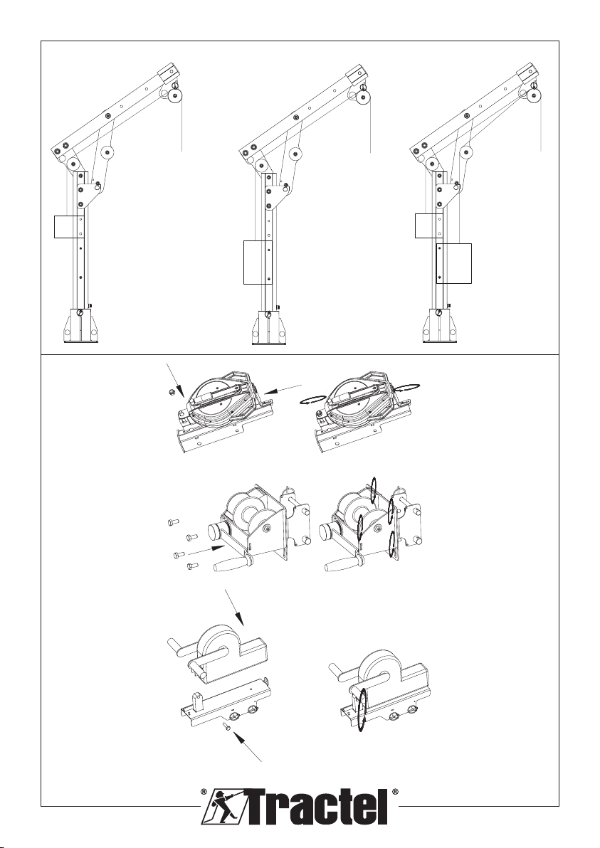
5.2.1. Installation of Carol™ winches on
the Carol™ Davitrac bracket ...............10
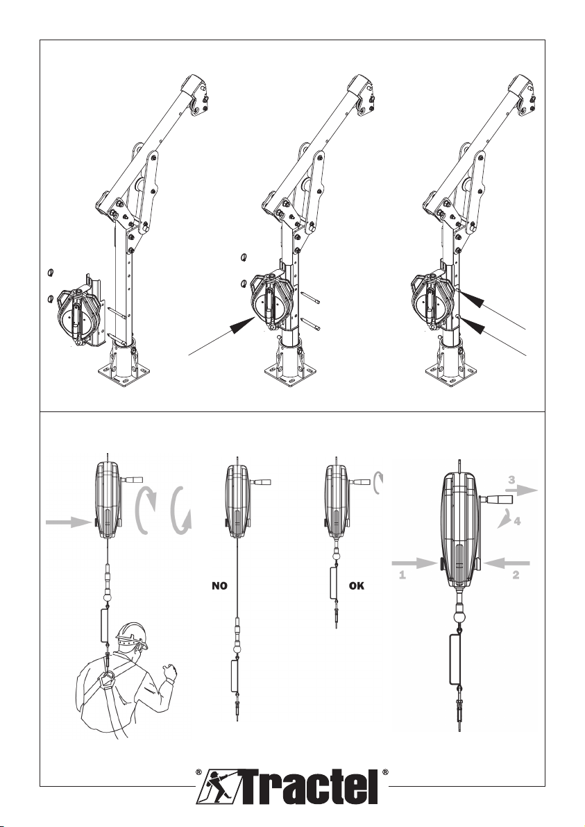
5.2.2. Installation of the Carol™ Davitrac
bracket on the mast of the Davitrac.....10
5.2.3. Dismantling of the Carol™ Davitrac
bracket.................................................10
5.3. Scafor™ R ....................................................10
5.3.1. Installation of the Scafor™ R winch
on the Scafor™ Davitrac bracket.........10
5.3.2. Installation of the Scafor™ Davitrac
bracket on the mast of the Davitrac.....10
5.3.3. Dismantling of the Scafor™ R
Davitrac bracket................................... 11
6. Use ....................................................................... 11
6.1. Blocfor™ 20R and 30R................................. 11
6.1.1. Rescue operation with Blocfor™ R...... 11
6.1.1.1. Activating the recovery
function.................................. 11
6.1.1.2. Return to the fall arrest
function.................................. 11
6.2. Carol™..........................................................12
6.2.1. Carol™ R.............................................12
6.2.1.1. Rescue operation with the
Carol™ R winch ....................12
6.2.1.2. Load lifting operation .............. 12
6.2.2. Carol™ TS...........................................12
6.2.3. Carol™ MO..........................................12
6.3. Scafor™ R ....................................................12
7. Prohibited use........................................................12
8. Associated equipment ........................................... 12
8.1. PPE...............................................................12
8.2. Lifting ...........................................................13
9. Transport and storage .......................................... 13
10. Equipment compliance ........................................13
11. Marking................................................................13
12. Periodic inspection and repair .............................13
12.1. Checking the cable .....................................14
12.1.1. Composition of the cable .....................14
12.1.2. Checking the general condition of
the cable ..............................................14
12.2. Checking the Blocfor™ R ...........................14
12.2.1. Checking the marking..........................14
12.2.2. Checking the compulsory
components are present......................14
12.2.3. Checking the general condition of
the fall arrest .......................................15
12.2.4. Checking the general condition of
the cable .............................................15
12.2.5. Checking the general condition of
the tear-o energy absorber ...............15
12.2.6. Checking the fall arrest function .......... 15
12.2.7. Checking the rescue lifting system ......15
12.3. Checking the Carol™ R, Carol™ TS
and Carol™ MO winches............................ 15
12.3.1. Checking the marking..........................15
12.3.2. Checking the compulsory
components are present......................16
12.3.3. Checking the general condition of
the Carol™ winch ...............................16
12.3.4. For the Carol™ MO ............................. 16
12.3.5. Checking the general condition of
the cable ..............................................16
12.3.6. Checking the proper functioning of
the Carol™ winch ................................16
12.3.6.1. Additional check for the
Carol MO...............................16
12.4. Checking the Scafor™ R ............................16
12.5. Checking the Blocfor™, Carol™ and
Scafor™ brackets .......................................16
12.5.1. Checking the marking..........................17
12.5.2. Checking the compulsory components
are present ..........................................17