Trademaster TM26005 User manual

Operator’s Manual for
10" Sliding Compound Mitre Saw
Model No. TM26005 UPC 7-72142-26005-4
Trademaster Parts & Service
205 Frobisher Drive
Waterloo, ON
N2V 2G4
tel: 866-332-3307
fax: 866-332-3308

GENERAL SAFETY INSTRUCTIONS
WARNING! Read and understand all instructions. Failure to follow all instructions listed below may result in
electrical shock, fire and/or serious personal injury.
SAVE THESE INSTRUCTIONS
Work Area
• Keep your work area clear, clean and well lit.
Cluttered work surfaces and dark areas invite
accidents.
• Keep people not involved in the work, especially
children away from the work area while operating
a power tool. Distractions can cause you to lose
control of the tool.
• Do not operate power tools in an unsafe
environment such as in an explosive atmosphere,
near flammable liquids, gases and dust. A spark
created by a power tool may ignite the fumes or dust.
• DON’T USE IN DANGEROUS ENVIRONMENT. Don’t
use power tools in damp or wet locations, or expose
them to rain. Keep work area well lighted.
Electrical Safety
• Double insulated tools are equipped with a
polarized plug (one blade is wider than the other.)
This plug will fit into a polarized outlet only one
way. If it does not fit fully in the outlet, reverse the
plug and try again. If it still does not fit fully, contact
a qualified electrician to install a polarized plug. Do
not modify the plug in any way. Double insulation
eliminates the need for the three wire grounded power
cord and grounded electrical system.
• Avoid body contact with grounded surfaces such
as radiators, pipes, ranges and refrigerators. There
is an increased risk of electrical shock if your body is
grounded.
• Do not operate power tools in the rain or wet
conditions. Water entering a power tool increases the
risk of electrical shock.
• Do not stress the power cord. Never carry the
power tool by the cord or disconnect the plug from
the receptacle by yanking on the cord. Keep cord
away from sharp edges, heat, solvents and oil.
Replace damaged cords immediately. Damaged cords
increase the risk of electrical shock.
• Use outdoor extension cords when operating the
power tool outside. Outdoor power cords are
marked "W-A" or "W" and are rated for outdoor use.
These cords reduce the risk of electrical shock.
Personal Safety
• Dress appropriately. Do not wear loose clothing
or jewelry. Keep long hair in place and contained.
Keep clothing, hair and gloves away from moving
parts. Loose clothing, jewelry and hair can be
snagged in moving parts.
•Use common sense, stay alert and watch what
you are doing while operating a power tool. Do
not use tools while under the influence of alcohol,
medication, or drugs. Keep focusing on the work at
hand while using a power tool to prevent personal
injury.
• Make sure the power switch is in the "OFF" position
before plugging it into the receptacle. This will
prevent accidental starting. Carrying tools with your
finger on the switch or plugging in the tools with the
switch in the "ON" position invites accidents.
• Remove adjusting tools such as wrenches or keys
before turning the tool on. A wrench or key left
attached to a rotating part will fly off and may cause
personal injury.
• Do not overreach while operating a power tool.
Keep proper footing and balance at all times. Good
balance and solid footing enables better control in
unexpected situations.
• Always wear appropriate safety equipment. Always
wear eye protection while operating a power tool.
Use appropriate dust respirators, hearing protection,
hard-hat, face shield or safety shoes as dictated by the
work and tool.
• NEVER STAND ON TOOL. Serious injury could
occur if the tool is tipped or if the cutting tool is
unintentionally contacted.
• NEVER LEAVE TOOL RUNNING UNATTENDED. TURN
POWER OFF. Don’t leave tool until it comes to a
complete stop.
WARNING
b) Keep hands out of path of saw blade.
c) Do not operate saw without guards in place.
d) Do not perform any operation freehand.
e) Never reach around saw blade.
Tool Use and Care
• Secure the work piece with clamps or other
practical methods to provide a secure work
platform. Holding the work by hand or against your
body is not secure and may lead to loss of control.
• Use the correct tool for the work. The proper tool
will do the work faster and safer.
• Do not use the tool if the "ON/OFF" switch is not
working. Operating a tool that cannot be controlled
by you is dangerous and must be repaired before use.

• Always disconnect the power cord from the
electrical outlet before storing the tool, making
adjustments or adding/replacing accessories. This
simple prevention will reduce the risk of accidental
starting of the tool.
• Store the tool in a secure place out of reach of
children. A secure storage location will prevent the
unauthorized use by untrained users.
• Properly maintain tools. Keep all cutting tools sharp
and clean. Remove contaminants from the tool and
keep clean. Check for broken parts or binding of
moving parts before use. If damaged, have the tool
serviced before use. Prevent accidents caused by
poorly maintained tools.
• Use only accessories recommended for your
model. Accessories suitable for one tool may become
hazardous when used on another tool.
• MAKE WORKSHOP KID PROOF with padlocks, master
switches, or by removing starter keys.
• DON’T FORCE TOOL. It will do the job better and
safer at the rate for which it was
designed.
• USE RIGHT TOOL. Don’t force tool or attachment to
do a job for which it was not designed.
Service
• Tool service, mechanical and/or electrical is to
be performed only by qualified repair personnel.
Service performed by unqualified personnel may
result in a risk of injury.
• When servicing a tool, use only identical
replacement parts. Use of unauthorized parts or
failure to follow maintenance instructions may create
a risk of electrical shock or injury.
Additional Safety Instructions for Mitre
Saws
• Wear safety goggles.
• Always wear appropriate safety equipment when
operating the tool.
• Do not use this tool in the presence of flammable
liquids or gases.
• The saw blade must be properly sharpened to ensure
maximum cutting capacity. Replace any deformed
or broken saw blades to avoid accidents before you
operate this tool.
• Use only the special flanges provided for this tool.
• Be careful not to damage the output spindle, flanges
(especially the fitting surfaces) and the bolt. Check
whether the saw blade is in good condition.
• Make sure the rotary table is secured firmly so that it
cannot move while it is operating.
• Clear chips and small blocks on the base to ensure a
smooth, clean surface.
• Before cutting any work pieces, make sure that the
nails and screws around the cutting position have
been cleared.
• Make sure that the armature shaft lock is in the off
position by the shaft locking arm before you turn it on.
• Make sure that the saw blade will not touch the rotary
table when the saw blade is in its lowest position.
• Never operate this tool with a single hand. Secure the
work piece with the vice. Holding the work by hand is
not secure and may lead to loss of control.
• Hold the handle of the saw firmly.
• Keep your hand away from the cutting line and do not
touch the saw blade during operation.
• Do not approach the saw blade during operation.
• Before switching on the motor, the saw blade must not
contact the work piece.
• Before carrying out any work, allow the motor to
idle for a while. Make sure there is no oscillation
caused by improper installing of the saw blade or the
unbalance of a warped saw blade.
• Start your work after the motor has reached its
maximum speed.
• If anything goes wrong during operation, switch the
tool off and stop working immediately.
• Do not try to fix the saw when the switch is in the
“ON” position.
• Before carrying out any maintenance and adjustment
of the saw, make sure to disconnect the power cord
from the electrical outlet and the saw blade has
stopped rotating.
• Stay alert and watch what you are doing while
operating the saw, especially in repeat and
monotonous operation. Do not create an illusive safe
feel, because the saw blade is dangerous.
• Be sure to use the accessories specified in this
manual.
• Do not damage the cord. Never carry the tool by the
cord or disconnect the plug from the receptacle by
yanking on the cord. Keep the cord away from heat,
oil and sharp edges.
• KEEP GUARDS IN PLACE and in working order.
• ALWAYS USE SAFETY GLASSES. Also use face or dust
mask if cutting operation is dusty. Everyday eyeglasses
only have impact resistant lenses, they are NOT safety
glasses.
• DIRECTION OF FEED. Feed work into a blade or
cutter against the direction of rotation of the blade or
cutter only.

Total Extension Cord Length (in feet)
Table A
25 50 100 150 200
AMP Rating Wire Gauge
0–10 18 14 12 10 8
10–12 16 14 10 8 8
12–14 14 12 10 8 6
14–16 14 12 10 8 6
16–18 12 12 8 8 6
Extension Cords:
Make sure your extension cord is not damaged. When
using an extension cord, be sure to use one heavy
enough to carry the current your product draws.
For lengths more than100 ft, No. 10 AWG extension
cords should be used. An undersized cord results in a
drop in line voltage and loss of power and overheating.
(NOTE: Table A below shows the correct size to use
depending on cord length and nameplate ampere
rating. When in doubt, use the next heavier gauge. The
smaller the gauge number, the heavier the cord.)
Using the Laser collimator system
WARNING: Do not stare directly at the laser beam.
Never aim the beam at any person or an object other
than the work piece.
Do not deliberately aim the beam at personnel and
ensure that it is not directed towards the eye of a person
for longer than 0.25s.
Always ensure the laser beam is aimed at a sturdy work
piece without reflective surfaces, i.e. wood or rough
coated surfaces are acceptable. Bright shiny reflective
sheet steel or the like is not suitable for laser use as
the reflective surface could direct the beam back at the
operator.
Only turn the laser beam on when the tool is on the work
piece.
1. Mark the line of the cut on the work piece.
2. Adjust the depth of the cut and bevel angle as
required.
3. Rest the front edge of the base on the work piece.
4. Switch on the laser beam using the laser light on/off
button.
5. Align the beam with the line on the work piece.
6. Start the motor by squeezing the trigger switch.
7. Always let the blade reach full speed (approximately
2 seconds) before you begin to cut into the work
piece.
8. Slowly push the saw forward using both hands,
keeping the red laser light beam on the line of cut.
9. After completing your cut, release the trigger switch
and allow the blade to come to a complete stop. Do
not remove the saw from the work piece while the
blade is moving.
10. Switch off the laser beam on completion of the cut.
Safety rules for laser lights
The laser guide used in the tool is Class II with a
maximum output of 1 mW and a wavelength of 650 nm,
Complies with 21 CFR, Subchapter J, Parts 1010 and
1040, Class II laser product. The laser guide does not
normally present an optical hazard, although staring at
the beam may cause flash blindness.
User Information
CAUTION – The use of optical instruments with this laser
product will increase eye hazard.
CAUTION – The use of controls or adjustments or
performance of procedures other than those specified
herein may result in hazardous radiation exposure.
• Do not stare into the laser beam.
• The laser shall be used and maintained in accordance
with the manufacturer’s instructions.
• Never aim the beam at any person or an object other
than the work piece.
• Do not disassemble the laser.
• Operate the laser only when cutting. Turn the laser off
after use.
Always ensure the laser beam is aimed at a sturdy work
piece without a reflective surface, i.e. wood or rough
coated surfaces are acceptable. Bright shiny reflective
sheet or the like is not suitable for laser use as the
reflective surface could direct the beam back at the
operator.
This label is located on the top of the motor enclosure
(part # 63).
This label is located on the top
of the rocker arm (#87) beside
the laser battery box (#145) and
switch of laser (#139).
This label is located
on the lower back
edge of the safety
guard (#105)

Technical Specifications
OPERATING INSTRUCTIONS
SAVE THESE INSTRUCTIONS
ITEM DESCRIPTION
Motor No-Load Speed:4600RPM
Power Supply 120V/60Hz/Single Phase/15 Amps
Arbor Diameter 0.625” (5/8")
Blade Diameter 10”
Cutting Capacity Cross cut 90°: 11.81” x 2.95” (300mm x 75mm)
Bevel cut 45° x 90°: 8.26” x 2.95” (210mm x 75mm)
Compound cut 45° x 45°: 8.26” x 1.57” (210mm x 40mm)
Mitre cut 45°: 11.81” x 1.57” (300 x 40mm)
Accessories 10” x 40T Carbide Tipped Blade
Material Hold Down Clamp
Material Support Brackets
Stop Plate For Repeated Cuts Of Same Dimension
Lug Style Arbor Wrench
Dust Bag
Spare Carbon Brushes
Changing the Saw Blade
To remove the saw blade loosen the bolt that fixes the
central cover by turning it counter clockwise using the
socket wrench provided. Then, raise the central cover
and move it down from the original position.
Central Cover
Socket Wrench
Shaft Locking
Arm
Socket Wrench
When removing the saw blade, first raise the lowest
position handle and press down the shaft locking arm to
lock the saw blade. Then loosen the hex bolt by turning
it clockwise using the socket wrench and remove the hex
bolt, the outer flange and the saw blade.
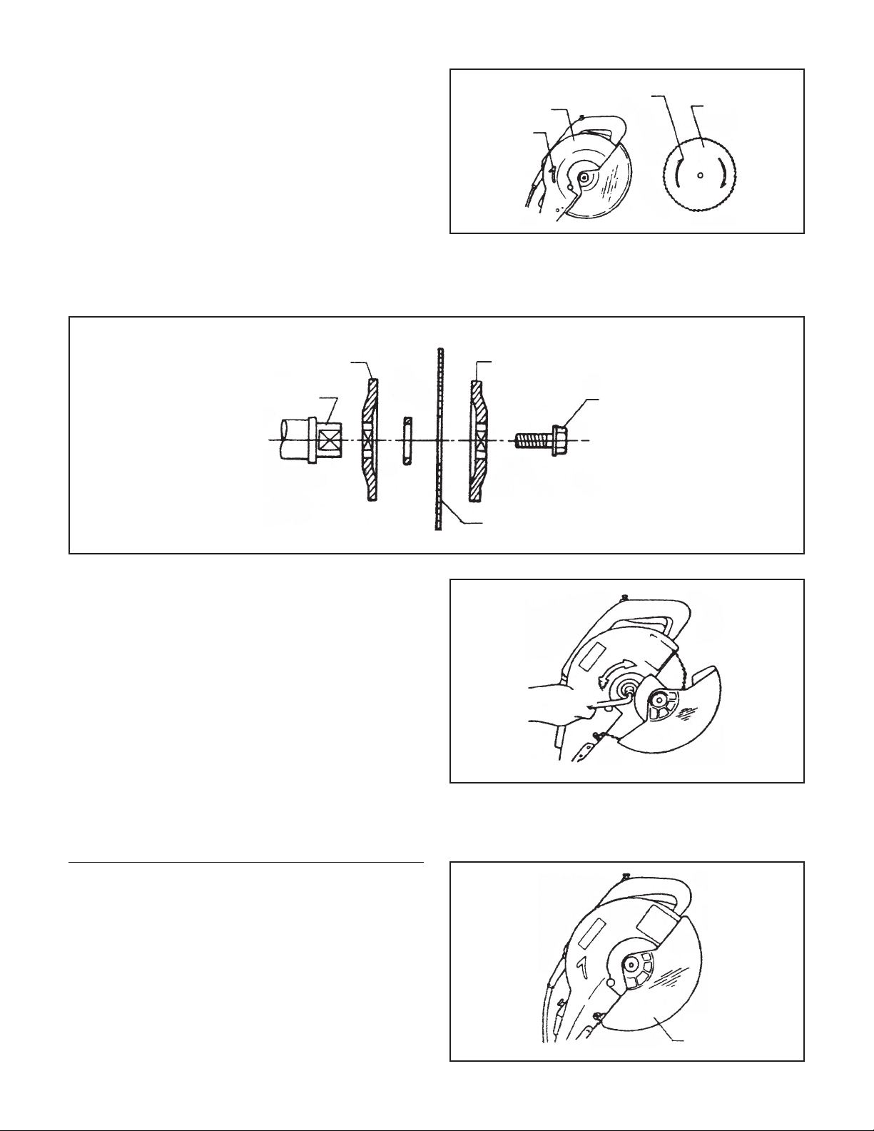
Install the outer flange and the hex bolt. Then, press
down on the shaft locking arm, and tighten the hex bolt
firmly by turning it counter clockwise using the socket
wrench. Adjust the hex bolt in a clockwise direction to fix
the central cover.
Blade Guard
When sawing, the blade guard will be lifted up by the
work piece. After you finish cutting, the blade guard will
automatically reset to its original position with the handle
raised. Never abandon or remove the blade guard.
Inner Flange
Install Shaft
Outer Flange
Hex Bolt
Saw Blade
Loosen
Tighten
Blade Guard
Protective
Cover
Arrow
Arrow Saw Blade
When installing the new saw blade check that the teeth
point in the direction of the arrow (See the protective
cover).

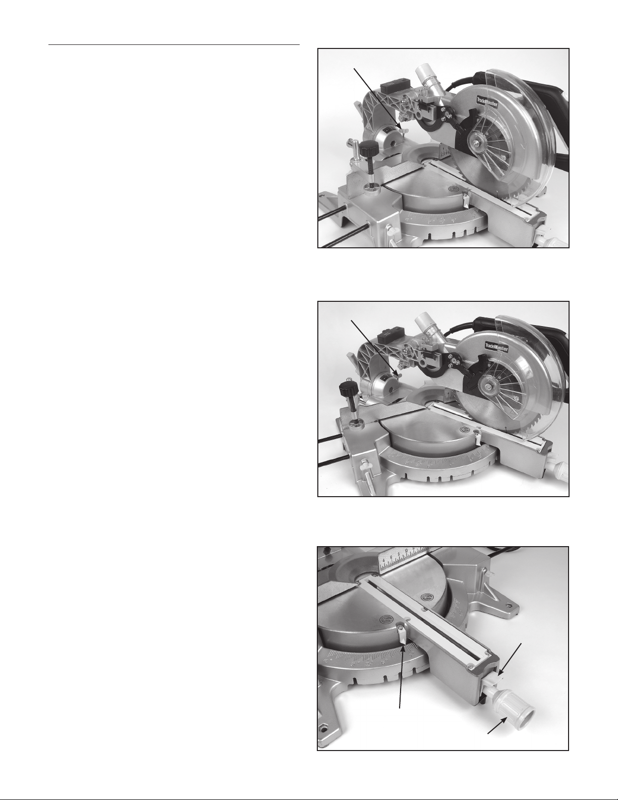
Sawdust Collector
You can operate this machine more conveniently with the
sawdust collector. Connect the adapter of the collector
to the nozzle of the protective cover, then, fix the collector
inlet to the adapter of the collector. When the sawdust
collector is half full, take the collector off of the protective
cover and open the collector door at the bottom. Clean
the sawdust out of the collector completely.
Operating the Switch
To prevent accidental starting, the tool is equipped with a
protective switch. To start the tool, you should first press
the protective switch and then press down the trigger
switch. The tool shuts off when you release the trigger
switch.
Sawdust Nozzle
Sawdust Collector
Collector Door
Protective Button
Trigger Switch
Replacing the Carbon Brushes
Check and remove the carbon brushes regularly. Replace
them when they wear down to the limit mark. Keep the
carbon brushes clean and free to slip in the holders.
Both carbon brushes should be replaced at the same
time.
Use a screwdriver to remove the brush holder caps. Take
out the worn carbon brushes and insert the new ones
and secure the brush holder caps.
Limit Mark
Screwdriver
Brush Holder Cap
Operation
Press Cut (cutting a small work piece)
The work piece size within the scope of 70mm(H) x
210mm(W) can be cut in the following way:
Push the carriage to the end towards the cross bar,
tighten the knob to fix the carriage. Then use the vice to
secure the work piece. Switch the machine on and wait
for the saw blade to reach its maximum speed before
slowly pressing the handle downwards. After you have
finished cutting, turn the switch off and wait until the
saw blade stops rotating before you completely raise the
handle.
Slip Cut (cutting a wide work piece)
The work piece size within the scope of 80mm(H) x
300mm(W) can be cut in the following way:
Release the knob to slip the carriage freely. Completely
pull the carriage towards the operator. Switch the
machine on and wait for the saw blade to reach its
maximum speed. Then press down on the handle and
push it to the cross bar to cut the work piece. After you
have finished cutting, turn the switch off and wait until
the saw blade stops rotating before you completely raise
the handle.
Setting a Bevelled Joint Angle
Loosen the hand shank by turning it counter clockwise.
Press down on the spring pin so that the rotary table is
free to turn. When the desired angle on the scale on the
base matches up with the arrow marked on the rotary
table, turn the hand shank clockwise to tighten it.
Knob
Knob
Indicator
Hand Shank
Spring Pin
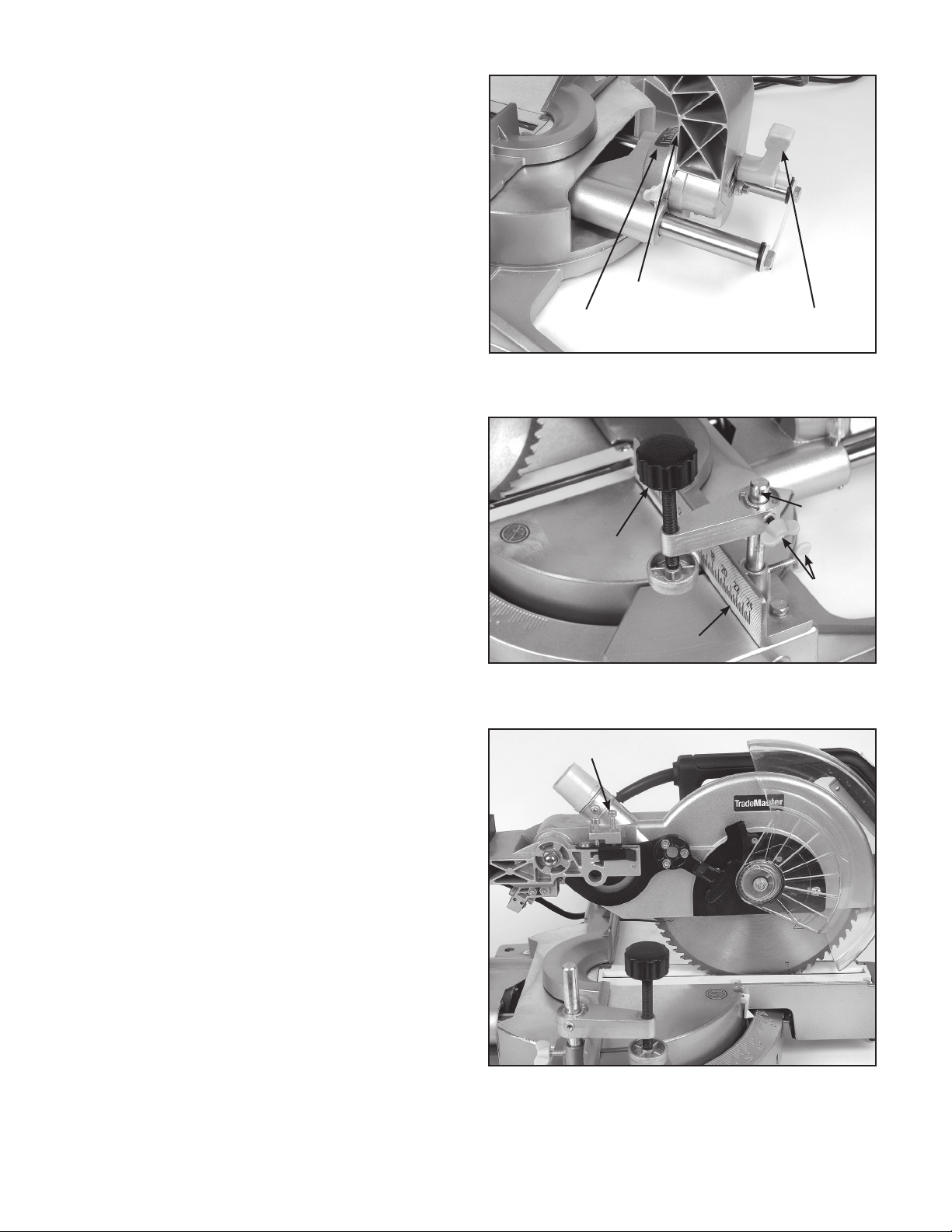
Setting a Bevelling Angle
Only when the auxiliary stopper is fixed on the left side,
as shown on the drawing, can the saw blade be bevelled
to a 45° angle. To adjust the bevelling angle, loosen the
fixed handle, then incline the saw blade to the left until
the indicator reaches the desired angle on the mitre
square. Then tighten the fixed handle firmly.
Indicator
Mitre Square Fixed Handle
Keep the Maximum Cutting Capacity
Before making any adjustments, remove the plug from
the socket. This machine has been adjusted by the
manufacturer to keep the maximum cutting capacity
using a ø210mm(8”) saw blade. When the diameter of
the sawblade becomes smaller, because of grinding,
adjust the machine by following the illustration: Push the
carriage to the cross bar direction and put the handle
to the lowest position. Turn the adjustable bolt using the
socket wrench to make the place where the saw blade
edge on the top of the rotary table surface and the front
surface of the cross bar intersect below the top surface
of the rotary table. Be sure the plug has been removed,
and then turn the saw blade with you hand. Press the
handle to its lowest position to check that the saw blade
does not contact the table. If necessary, you can adjust it
a bit.
Note: Before installing the new saw blade, make sure the
saw blade does not contact the table.
Secure the Work piece
The vertical vise can be installed in the hole of the guide
bar or the work piece supporter component (selective
purchasing). Install the vise rod in the hole of the guide
bar or work piece supporter component and then tighten
the bolt. You should adjust the position of the vise arm
according to the shape and thickness of the work piece
and tighten the vise arm with the bolt. Lean the work
piece against the guide bar and the rotary table and
place the work piece in the desired cutting position. Then
tighten the clamp bolt to secure the work piece.
Clamp Bolt
Guide Bar
Bolt
Vise Rod
Adjusting Bolt
1716
15
14
13
11
10
9
8
12
7
6
5
4
3
2
1
18
19
20
21
22
23
24
25
26
27
28
29
30
31
32
33
34
35
36
62
63
64
65
66
67
68 69 70
72 73 74 75
76 77 78
79
80
71
44
45 46
47 48
49
51 52 53
54
55
61
60 59 58
57 56
42
41
40 39 38 37
43
145
144
142
143
141
113 112
111 110 108 107
106
105
109
81
82 83 84 85
104
86 87
88 89
91
90 92 93
103
102
101
100
99
98 97
96
95
124
123
122
118 117
114
115
120
121
125
116
126
127
128
129 130 131 132
133
134
135
136
137
138
139
140
119
147
146
94
50
157
158
159
160 161 162
163
164
148
149
150
151
152
153
154
155
156
TM26005
02/2009

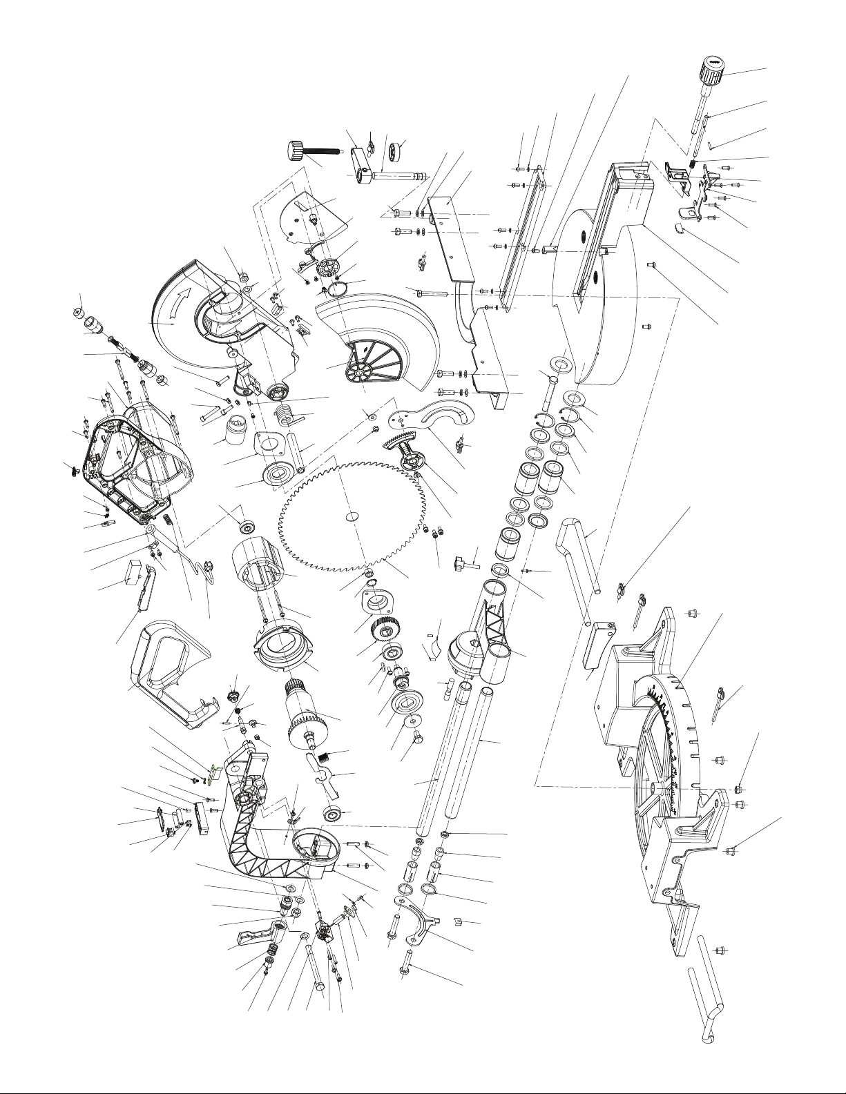
Item Description Qty.
110 Screw 1
111 Sliding Bar Ring 1
112 Screw M4X10 1
113 Needle 1
114 Cap Nut M10 1
115 Flat Washer D10 1
116 Cross Screw M4X6 2
117 Cross Screw M4X10 2
118 Positioning Plate 1
119 Cross Screw M6 1
120 Cross Screw ST3.5X9C 2
121 Safety Fence 1
122 Movable Safety Guard 1
123 Washer D6 1
124 Cross Screw ST3.5X9C 2
125 Spring 1
126 Column Pipe 1
127 Nylon Nut M6 1
128 Hex Bolt M8X55 1
129 Spring 1
130 Cross Screw M4X6 1
131 Gear 1
132 Cover of Gear 1
133 Fixed Plate of Movable
Safety Guard 1
134 Positioning Handle 1
135 Vise Jaw 1
136 Short Handle M6×20 1
137 Lever of Vise 1
138 Press Plate 1
139 Outer Hex Bolt M8×30 4
140 Elastic Washer D8 4
141 Flat Washer D8 4
142 Fence 1
143 Cross Screw M5X12 6
144 Flat Washer D5 6
145 Kerf Board 1
146 Cross Screw M5X12 1
147 Needle 1
148 Rivet 2
149 Cross Screw M4X10 2
150 Battery Box 1
151 Spring 1
152 No.7 Battery 2
153 Cover of battery box 1
154 Switch of Laser 1
155 Spring 1
156 Spring 1
157 Holder of Laser 1
158 Cross Screw M4X20 3
159 Cross Screw M4X16 3
160 Laser 1
161 Bushing of Laser head 1
162 Cover of laser head 1
163 Flat Washer D4 1
164 Cross Screw M4X10 1
Item Description Qty.Item Description Qty.
1 Rubber Bracket 4
2 Nylon Nut M8 1
3 Long Handle M6×70 2
4 Base 1
5 Plastic Fence 1
6 Short Handle M6×20 1
7 Extension 2
8 Cross Screw M6×12 2
9 Worktable 1
10 Rubber Washer 1
11 Sunk Head Screw
M5×12 6
12 Indexing Cover Plate 1
13 Indexing Spanner 1
14 Indexing Spring 1
15 D3×20 Pin 1
16 Indexing Pin 1
17 Indexing Handle 1
18 Outer Hex Bolt M10×85 1
19 Big Rubber Ring 2
20 Ring D40 2
21 Dustproof Cover 4
22 Felt Ring 4
23 Linear Bearing 3
24 Cross Screw M4×10 1
25 Braking Ring 1
26 Short Handle M6×10 1
27 Bracket 1
28 Screw M8×35 1
29 Short Sliding Bar 1
30 Hex Nut M10 2
31 Holder 2
32 Ring 2
33 Small Rubber Ring 2
34 Bracket of Sliding
Bar Support 1
35 Sliding Bar Support 1
36 Outer Hex Bolt M10×50 2
37 Short Handle M6×20 2
38 Sliding Slot of Gear 1
39 Big Gear 1
40 Screw M6 1
41 Inner Hex Bolt M5X12 3
42 Saw-Blade 1
43 Scale 1
44 Shaft Bolt 1
45 Shaft Washer 1
46 Outer Flange 1
47 Shaft 1
48 Cross Screw M5×16 2
49 Key 1
50 Ball Bearing 6203-2RZ 1
51 Helical Gear 1
52 Gear Holder 1
53 Spring D17 1
54 Oily Bearing 1
55 Stator Assembly 1
56 Cross Screw M5×70 2
57 Wind Resist Ring 1
58 Rotor 1
59 Handle 1
60 Blade Lock 1
61 Long Sliding Bar 1
62 Ball Bearing 6201-2RZ 1
63 Hex Nut M6 2
64 Inner Hex Screw M6×25 2
65 Rocker Arm 1
66 Outer Hex Bolt
M10×100 1
67 Flat Washer D10 1
68 Cross Screw M4×10 1
69 Push handle 1
70 Spring 1
71 Lock Bolt Assembly 1
72 Nylon Ring Nut M10 1
73 Lock Nut Assembly 1
74 Flat Washer D10 1
75 Washer D10 1
76 Cross Screw M4 1
77 Wave Type Washer 1
78 Stopper Plate 1
79 Handle Cover 1
80 Switch Actuator 1
81 Screw ST3.5×13C 2
82 Switch 1
83 Cord Plate 1
84 Cord Guard 1
85 Stop bolt Spanner 1
86 Spring 1
87 Screw ST3.5×9C 1
88 Stop bolt 1
89 Screw ST3.5×16F 7
90 Cross Screw M5×45 4
91 Motor Enclosure 1
92 Carbon Brush 2
93 Brush Holder 2
94 Cover of Brush Holder 2
95 Safety Guard 1
96 Cross Screw M6X25 1
97 Hex Nut M6 2
98 Inner Hex Bolt M6X40 1
99 Inner Hex Bolt M6X20 1
100 Dust Bag Port 1
101 Cover of Bearing 1
102 Inner Flange 1
103 Ball Bearing 6200-2RZ 1
104 Spring 1
105 Power Supply Cord 1
106 Lock Pin Handle 1
107 Pin D2.5×14 1
108 Spring 1
109 Lock Pin 1
Parts List

LIMITED WARRANTY
TradeMaster Parts & Service (TMPS) warrants to the original
purchaser only that its TradeMaster brand power tools will be
free from defects in material or workmanship for a period of
three years from the date of purchase.
In the event this power tool fails, return the complete tool,
transportation prepaid, to your nearest Authorized Service
Centre. We will repair at our option, any part of the product
covered under this warranty which, after examination, proves
to be defective in workmanship or material during the
warranty period.
Original Bill of Sale is required.
This warranty does not apply to any repairs required if the
tool is put to use other than intended, it has been misused,
abused, carelessly or accidentally mishandled, normal wear
and tear, repairs attempted or made by other than TMPS
or Authorized Service Center. This limited warranty does
not apply to accessory items such as circular saw blades,
drill bits, router bits, jigsaw blades, sanding belts, paper or
discs, grinding wheels and other related items. In no event
shall TMPS be held liable for any incidental or consequential
injury, death or damage arising from the sale and subsequent
use of this product. This is TMPS TradeMaster sole warranty
and explains a customer’s exclusive remedy with respect to
defective product. Under no circumstances will TMPS’s liability
under this warranty exceed the purchase price of the product.

Blade change for TM26005
Loosen this screw to release the guard fixed plate
Push the entire plastic guard assembly forward.
You will see the slot in the front of the fixed plate
that the front screw pivots on.
When pushing the guard forward, notice the gear
for the guard guide system separates, note this
as you will have to align this when putting the
guard back into place.
Pull the guard up and over the metal safety guard
It should sit out of the way and you now have
access to the blade and blade bolt.
From here follow the directions on the manual from the point of locking the shaft.
Please note that the blade bolt is Left Hand thread so you will be turning right to loosen it.
Table of contents
Other Trademaster Saw manuals


Popular Saw manuals by other brands

Zipper Mowers
Zipper Mowers ZI-WP700H Operation manual

Master Cut
Master Cut 60089 owner's manual

Rotorazer Saw
Rotorazer Saw 3000 Series user manual

Rockwell
Rockwell 10" Contractors' Saw instruction manual

MEP
MEP PH 100 Instruction manual and spare parts list

skilsaw
skilsaw SPT77WML Operating/safety instructions


