trafag Simple Apparatus 904.71 User manual
1
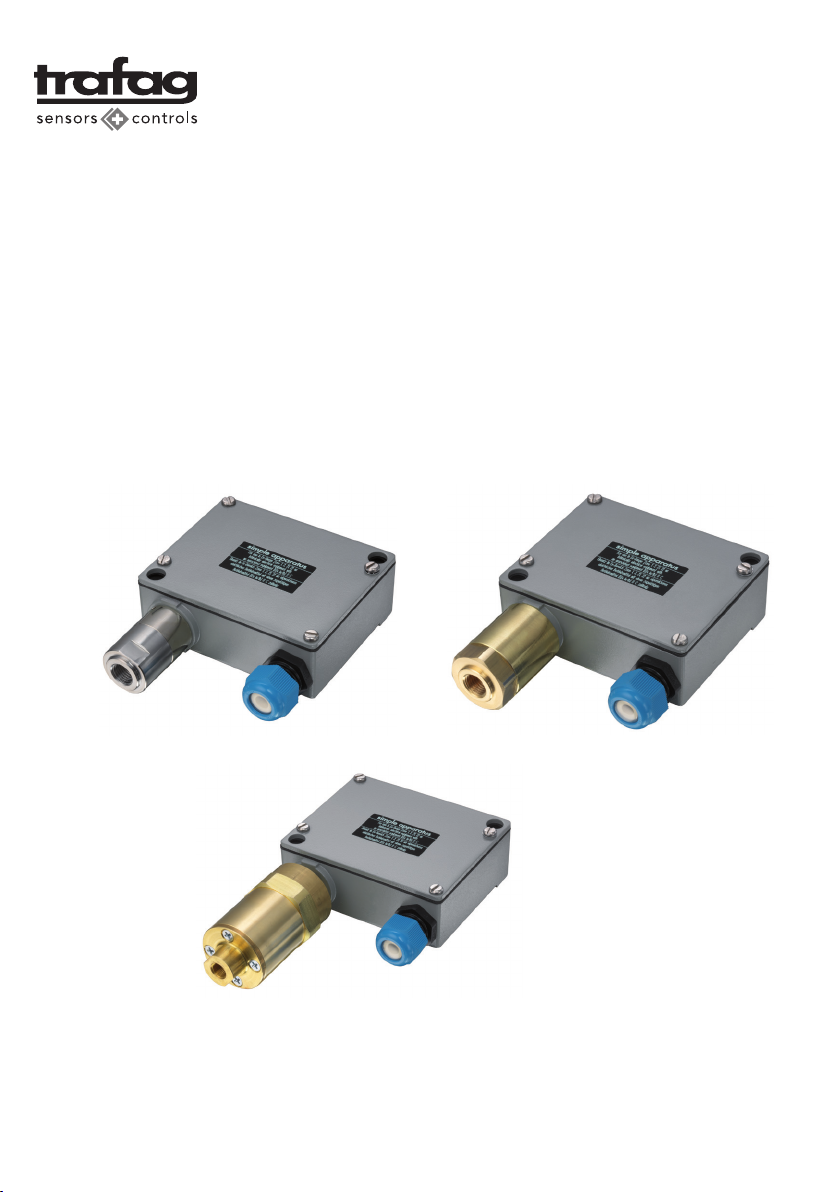
Pressostat Bellows Type „Simple Apparatus“ 904.71
Pressostat Piston Type „Simple Apparatus“ 947.71
Pressostat Differential Pressure Type „Simple Apparatus“ 924.71
ATEX-konform/Conforme ATEX/Conformity to ATEX
Betriebsanleitung
Mode d’emploi
Operating instructions
Tra
f
ag AG Tel +41 44 922 32 32
Industriestrasse 11 Fax +41 44 922 32 33
CH-8608 Bubikon www.trafa
g
.com
2
Pressostaten
904.71.../947.71.../924.71...
(ATEX-konform)
Zielgruppe:
Erfahrene Elektrofachkräfte gemäss Be-
triebssicherheitsverordnung und unterwie-
sene Personen.
Inhalt:
1. Sicherheitshinweise
2. Normenkonformität
3. Technische Daten
4. Installation
5. Erstinbetriebnahme
6. Inspektion, Wartung und Instandhaltung
7. Entsorgung
1. Sicherheitshinweise
Der Druckschalter ist nicht für den Einsatz
in den Zonen 0 und 20 geeignet.
Betreiben Sie den Druckschalter bestim-
mungsgemäss im unbeschädigten und
sauberen Zustand und nur dort, wo die
Beständigkeit der Materialien gewähr-
leistet ist.
Die Schutzart IP 65 nach EN 60529 ist bei
korrektem Zusammenbau gewährleistet.
Es dürfen keine Veränderungen am Druck-
schalter vorgenommen werden, die nicht
ausdrücklich in dieser Betriebsanleitung
aufgeführt sind.
Beachten Sie bei allen Arbeiten am Druck-
schalter die nationalen Sicherheits- und
Unfallverhütungsvorschriften und die
nachfolgenden Sicherheitshinweise in
dieser Betriebsanleitung, die wie dieser
Text in Kursivschrift gefasst sind!
Pressostats
904.71.../947.71.../924.71...
(Conformity to ATEX)
Target group:
Experienced electricians as defined by the
Operating Safety Ordinance and properly
instructed personnel.
Contents:
1. Safety instructions
2. Conformity with standards
3. Technical data
4. Installation
5. Initial start-up
6. Inspection, Maintenance and Repair
7. Disposal
1. Safety instructions
Pressure switches are not suitable for use
in zones 0 and 20.
Use the pressure switch only for its intended
purpose and only in clean, undamaged
condition and only for duties where it is
certain that the materials are compatible
with the environment.
The requirements of IP 65 specified by EN
60529 are guaranteed in case of correct
assembly.
Do not make any modifications to the pres-
sure switch that are not expressly mentioned
in this Instruction Manual.
Whenever work is done on the pressure
switch, be sure to observe the national
safety and accident prevention regulations
and the safety instructions given in this
Instruction Manual, which are stated in
italics like this paragraph!
Pressostats
904.71.../947.71.../924.71...
(Conforme ATEX)
Groupe cible:
Électriciens expérimentés selon la régle-
mentation pour la sécurité et la santé et
personnel instruit.
Sommaire :
1. Sécurité
2. Conformité aux normes
3. Caractéristiques techniques
4. Installation
5. Première mise en service
6. Inspection, entretien et maintenance
7. Elimination
1. Sécurité
L’interrupteur à pression n’est pas appro-
prié à une application en zones 0 et 20.
Utiliser L’interrupteur à pression conformé-
ment aux prescriptions, en état de propreté
et dans un emplacement où l’inaltérabilité
est assurée et seulement là où la stabilité
des matériaux est assurée.
l’indice minimal de protection IP 65 selon
EN 60529 est garanti en cas de montage
correct.
Aucune modification n’étant pas expliquée
expressément dans la notice de service
ne doit être apportée à l’interrupteur à
pression.
Pour tous les travaux touchant l’interrup-
teur à pression, il y a lieu d’observer les
prescriptions nationales de sécurité et de
prévention des accidents ainsi que les
indications de la présente notice ayant
trait à la sécurité. A l’instar du présent
alinéa, ces indications sont imprimées
en italique.

3
2. Normenkonformität
Die Druckschalter entsprechen den Anfor-
derungen der EN 60079-0, EN-60079-11
sowie EN60730-1 und EN 60730-2-6.
Diese wurden entsprechend dem Stand der
Technik und gemäss der ISO 9001:2000
entwickelt, gefertigt und geprüft.
3. Technische Daten
3.1 Kennzeichnung
Einfaches Betriebsmittel
„simple apparatus“
3.2 Gehäusematerial
AlSi10Mg/ Epoxy beschichtet
3.3 Schaltleistung
3.4 Nenn-Aderquerschnitt
1.5 mm2
3.5 Gehäuseschutzart
IP 65
3.6 Zulässige Umgebungstemperatur
–25°C bis +70°C
4. Installation
Für das Errichten/Betreiben sind die allge-
mein anerkannten Regeln der Technik, die
EN 60079-14 «Projektierung, Auswahl
und Errichtung elektrischer Anlagen»,
nationale Vorschriften und diese Betriebs-
anleitung massgebend.
Die auf dem Typenschild angegebenen
Nenndaten der Druckschalter und allfälli-
ge Zusatzangaben des Herstellers müssen
berücksichtigt werden.
2. Conformity with standards
The pressure switches comply with the re-
quirements of the standards EN 60079-0,
EN 60079-11 as well as EN60730-1 and
EN 60730-2-6.
They have been developed, manufactured
and inspected using state-of-the-art technolo-
gy and in compliance with ISO 9001:2000.
3. Technical data
3.1 Marking
„simple apparatus“
3.2 Enclosure material
AlSi10Mg/ Epoxy coated
3.3 Rating
3.4 Nominal core cross-section
1.5 mm2
3.5 Enclosure degree of protection
IP 65
3.6 Admissible ambient temperature
–25°C bis +70°C
4. Installation
For installation and operation, the rules of
generally accepted engineering practice,
the provisions of EN 60079-14: ‚Electrical
installations design, selection and erec-
tion‘ and the instructions set out in this
manual must be observed.
The design data given on the rating plate
of the pressure switches and any addi-
tional data provided by the manufacturer
must always be taken into account.
2. Conformité aux normes
Les interrupteurs à pression répondent
aux exigences des normes EN 60079-0,
60079-11 ainsi que EN60730-1 et
EN 60730-2-6.
Ils ont de plus été développés, fabriqués
et testés selon l’état actuel de la techni-
que et conformément à la norme ISO
9001:2000.
3. Caractéristiques techniques
3.1 Marquage
Appareil simple
„simple apparatus“
3.2 Matériel du coffret
AlSi10Mg/ Vernis avec époxy
3.3 Pouvoir de coupure
3.4 Section du conducteur
1.5 mm2
3.5 Indice de protection du coffret
IP 65
3.6 Température ambiante
–25°C bis +70°C
4. Installation
Les règles techniques généralement recon-
nues EN 60079-14: «Conception, sélection
et construction des installations électriques»
et la présente notice sont déterminantes
pour l’installation et le service.
Les données nominales figurant sur la
plaque signalétique des interrupteurs à
pression et de même que les éventuelles
indications du fabricant devront être prises
en considération.
Typ Merkmale Schaltleistung
Type Caractéristiques Pouvoir de coupure
Type Features Rating
max.
71 Mit Goldkontakten U0 = 24 V
Avec contacts dorés I0= 100 mA
Gold plated contacts P0 = 600 mW

4
4.1 Allgemeines
Der Druckschalter dient innerhalb von
explosionsgefährdeten Bereichen zur be-
triebsmässigen Druckregelung.
Für den Einsatz ist zwingend eine Ex-i
Trennbarriere mit ATEX Bescheinigung
[Ex ia] IIC erforderlich.
4.1 Généralités
L’interrupteur à pression est appliqué en
emplacement dangereux pour la régulation
de pression en service.
Une barrière Ex-i avec certificat ATEX
[Ex ia] IIC est requis contraignant pour
l’installation.
4.1 General points
Pressure switches are used for controlling
the pressures in potentially explosive atmos-
pheres. The pressure switches are designed
for stationary installation only.
An Ex-i barrier with ATEX approval
[Ex ia] IIC must be installed in the set-up.
U0... 24 V
I0... 100 mA
P0... 0,6 W
L0... 8mH
C0... 100nF
Ex ia IIC
Ui> U0
Ii > I0
Pi> P0
„Simple Apparatus“ Pressure switch Associated Apparatus Ex-i Relais
}
}
}
o
oo
4
2
11+
2+
3-
8
7
9
10
11
12
14
15
230V AC
I
II
P
}
}
}
8
7
9
I
II
10
11
12
14
15 24V DC
24V DC
ERR
o
oo
4
2
11+
2+
3-
P
Switching example with Ex-i barrier F90141:
Switching example with Ex-i barrier F90140:
If another type of Ex-i relay is used, make sure its electrical rating limits are within the specification of the
pressure switch.
Rating:
Ui= 24 V
Ii= 100 mA
Pi= 0,6 W
Li= 0
Ci= 0
Hazardous Area Non Hazardous Area

5
4.2 Umgebungstemperatur
Zur Einhaltung der zulässigen maximalen
Oberflächentemperatur darf die Umge-
bungstemperatur (Betriebstemperatur) den
Bereich von –25°C bis +70°C nicht unter-
bzw. überschreiten. Zu beachten sind bei
der Betrachtung der Temperaturverhältnisse
auch Einflüsse von weiteren vorhandenen
Wärmequellen (Prozesswärme). Diese dür-
fen nicht zu einer zusätzlichen Erwärmung
des Druckschalters führen.
4.3 Montage
Der Druckschalter ist nur zur festen Mon-
tage vorgesehen.
4.4 Einbau des Druckfühlers
Der Druckfühler muss so eingebaut werden,
dass die Geometrie in keiner Art und Weise
verändert wird.
4.5 Elektrischer Anschluss
Der elektrische Anschluss (nach der Norm
DIN 46199 «Anschlussbezeichnung») ist
gemäss der Abbildung 5 auszuführen. Es
ist besonders darauf zu achten, dass die
Öffner- oder Schliesserkontakte bestim-
mungsgemäss angeschlossen werden.
Vor der Inbetriebnahme muss die Richtigkeit
der Anschlüsse überprüft werden.
Die Nichteinhaltung der angegebenen
Werte oder die Verwechslung der Kon-
takte ist gefährlich!
Klemme 1: Eingang Phase
Klemme 2: Öffner (Ausgang Phase)
Klemme 4: Schliesser (Ausgang Phase)
4.8 Klemmen
Die Druckschalter werden werkseitig mit einer
Schraubklemme ausgerüstet. Folgendes Dreh-
moment muss eingehalten werden:
Anzugsdrehmoment: 0,4 Nm
Querschnitt: max. 2,5 mm2
Alle Schrauben und/oder Muttern der
Anschlussklemmen, auch die der nicht
benutzten, sind fest anzuziehen. Bei über-
mässigem Anziehen kann der Anschluss
beeinträchtigt werden.
4.2 Ambient temperature
to keep the surface temperature below the
permitted maximum, it must be ensured
that the ambient temperature (operating
temperature) remains within the range
–25°C to 70°C. The effects of any other
local heat sources (process heat) must
also be taken into account. These must not
cause an additional temperature rise at the
pressure switches.
4.3 Installation
The pressure switch is only designed for
fixed installation.
4.4 Installation of the pressure sensors
The pressure sensor must be installed in
such a way that its geometry is not altered
in any way.
4.5 Electrical connection
Make up the electrical connection (to
standard DIN 46199 «connection desig-
nation») as shown in Figure 5. Particular
attention has to be paid to connecting the
normally closed and the normally open
contacts correctly.
Prior to startup it is necessary to verify
the correctness of these connections once
again.
Non-observance of the stated figures or
interchanging of the contacts is danger-
ous!
Terminal 1: input phase
Terminal 2: output phase to opener
Terminal 4: output phase to closure
4.8 Terminals
Pressure switches are fitted with a terminal
screw in the factory. Following tightening
torques must be complied with:
tightening torque: 0,4 Nm
cross section: max. 2,5 mm2
All screws and/or nuts on the terminals,
including those that are not in use, must be
securely tightened. Applying excess torque,
however, can damage the connection.
4.2 Température ambiante
Afin de garder la température superficielle
maximale admise, la température ambiante
(température de service) ne doit être ni
inférieure ni supérieure à la fourchette de
–25°C à +70°C. Il y a lieu de tenir compte
de l’influence d’autres sources de chaleur
éventuelles (température de procédé).
Celles-ci ne doivent pas contribuer à un
échauffement supplémentaire d’interrup-
teur à pression.
4.3 Montage
L’interrupteur à pression est conçu pour le
montage fixe exclusivement.
4.4 Montage du capteur de pression
Le capteur de pression doit être monté de
manière à ce que la géométrie ne soit en
aucune façon modifié.
4.5 Raccordement électrique
Le raccordement électrique (conforme à la
norme DIN 46199 «Marquage des bornes
de connexion») doit être effectué selon la
fig. 5 cicontre. Une attention particulière
doit être prise pour connecter correctement
les contacts normalement ouvert et norma-
lement fermé.
Avant la mise en service, il est nécessaire
de vérifier que les raccordements aient été
effectués correctement.
Le non-respect des valeurs indiquées ou
une confusion des contacts est dangereux!
Borne 1: entrée phase
Borne 2: sortie phase ouverture
Borne 4: sortie phase fermeture
4.8 Bornes
Les interrupteurs de pression sont équipées
en fabrique avec une borne à vis. Le moment
de rotation suivant doit être respecté:
moment de rotation: 0,4 Nm
section: max. 2,5 mm2
Toutes les vis et tous les écrous des bornes
de connexion doivent être serrés, mêmes
celles et ceux qui ne sont pas utilisés. Un
serrage exagéré est cependant susceptible
de nuire à la connexion.
Abbildung/Figure 5: Anschlussschema/Schéma de connexion/ Connection diagram
This manual suits for next models
2
Table of contents


