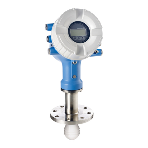
Micropilot FMR51, FMR52 PROFIBUS PA Table of contents
Endress+Hauser 3
Table of contents
1 Important document information ................................................ 4
1.1 Symbols ............................................................................ 4
2 Basic safety instructions ......................................................... 6
2.1 Requirements for the personnel ........................................................... 6
2.2 Designated use ....................................................................... 6
2.3 Workplace safety ...................................................................... 7
2.4 Operational safety ..................................................................... 7
2.5 Product safety ........................................................................ 7
3 Product description .............................................................. 8
3.1 Product design ....................................................................... 8
4 Incoming acceptance and product identification .................................. 9
4.1 Incoming acceptance ................................................................... 9
4.2 Product identification ................................................................. 10
5 Storage, Transport .............................................................. 11
5.1 Storage conditions .................................................................... 11
5.2 Transport product to the measuring point ................................................... 11
6 Installation ..................................................................... 12
6.1 Installation conditions ................................................................. 12
6.2 Measuring conditions ................................................................. 18
6.3 Mounting cladded flanges .............................................................. 20
6.4 Installation in vessel (free space) ......................................................... 20
6.5 Installation in stilling well .............................................................. 25
6.6 Installation in bypass .................................................................. 26
6.7 Vessels with heat insulation ............................................................. 27
6.8 Turning the transmitter housing ......................................................... 27
6.9 Turning the display module ............................................................. 28
6.10 Post-installation check ................................................................. 29
7 Electrical connection ............................................................ 30
7.1 Connection conditions ................................................................. 30
7.2 Connecting the device ................................................................. 34
7.3 Post-connection check ................................................................. 36
8 Integration into a PROFIBUS network ........................................... 36
8.1 Overview of the device database files (GSD) ................................................. 36
8.2 Set device address .................................................................... 37
9 Commissioning (via operating menu) ........................................... 39
9.1 Display and operating module ........................................................... 39
9.2 Operating menu ..................................................................... 42
9.3 Unlock the device .................................................................... 43
9.4 Setting the operating language .......................................................... 43
9.5 Configuration of a level measurement ..................................................... 44
9.6 User-specific applications ............................................................... 45
