TrafSys Walker Wireless THM3020 User manual

W
Wi
ir
re
el
le
es
ss
s
O
Ov
ve
er
rh
he
ea
ad
d
T
Th
he
er
rm
ma
al
l
S
Se
en
ns
so
or
r
M
Mo
od
de
el
l:
:
T
TH
HM
M3
30
02
20
0
Traf-sys/Walker Wireless, Inc | 190 Industry Drive –Pittsburgh, PA 15275 Page 1 of 18
Ph: 888-815-6568 | Fax: 928-222-7279 | www.trafsys.com
Introduction
The Traf-sys/Walker Wireless Wireless Overhead
Thermal Sensors are a discreet and highly
accurate solution to track foot traffic through a
given area or entrance. The counter consists of
two parts, a base and the sensor, and determines
traffic using heat signatures from customers’
heads; upon a heat signature crossing configured
IN/OUT lines, a count of the appropriate direction
is transmitted to the wireless transmitter.
Table of Contents
Introduction.....................................................................................................................1
Table of Contents............................................................................................................1
Required Equipment........................................................................................................1
Mounting and Orientation................................................................................................2
Single Sensor Entrance...............................................................................................2
Calibrating the Sensors...................................................................................................4
Required Equipment for Calibration.............................................................................4
Attaching the Setup Module.........................................................................................4
Single Sensor Entrance Calibration.............................................................................6
Multiple Sensor Entrance Calibration.........................................................................14
Troubleshooting ............................................................................................................16
Thermal Issues..........................................................................................................16
Mounting Issues........................................................................................................16
Software Issues.........................................................................................................16
Safety and Occupancy Issues...................................................................................16
LED Codes................................................................................................................17
Appendix A: Sensor Base Wiring...................................................................................18
Required Equipment
Traf-sys/Walker Wireless Thermal Sensor Configuration Software
Windows XP or later laptop PC with an available 9 pin RS-232 Serial Port.
THM3020S Setup Module (do not attempt to use any other setup module).
Straight and Philips head screwdrivers (not included)
Mounting bolts/screws (not included)
Wall mount bracket or ceiling mounting plate (optional; not included)
Wireless Transmitter and Power Supply (included in kit)
RJ-45 patch cables (included in kit)
Category 5 Ethernet cable for multiple sensor connection (not included)
Female to female RJ-45 Category 5 Ethernet jacks (two per sensor)
Cable/jack tester

W
Wi
ir
re
el
le
es
ss
s
O
Ov
ve
er
rh
he
ea
ad
d
T
Th
he
er
rm
ma
al
l
S
Se
en
ns
so
or
r
M
Mo
od
de
el
l:
:
T
TH
HM
M3
30
02
20
0
Traf-sys/Walker Wireless, Inc | 190 Industry Drive –Pittsburgh, PA 15275 Page 2 of 18
Ph: 888-815-6568 | Fax: 928-222-7279 | www.trafsys.com
Mounting and Orientation
The accuracy and reliable operation of the Wireless Overhead Thermal Sensor is
largely dependent on proper mounting and orientation of the sensor(s). Per Figure 1,
always be sure that the sensor’s LEDs are closest to the inside of the store.
Figure 1
Always follow these guidelines when installing sensors:
60° (low mount) sensors accommodate heights between 7’3” and 15’9”.
40° (high mount) sensors accommodate heights between 11’5” and 24’7”.
Sensors are always mounted at an entrance inside of a store/facility; never
outside or in a vestibule.
Keep field of vision of the sensor(s) free from obstruction (e.g. hanging
signage or walls).
Cable connections are not data cables; they are simply made from the same
cable type. Do not alter or rewire the cabling connections.
Ensure that the sensor base is mounted parallel to the ceiling and securely
and flat against its mounting surface (ceiling, plate or bracket).
Single Sensor Entrance
A single sensor can be used when the mounting height allows the sensor’s field
of view to equal or exceed the width of the entrance. Figure 2 below illustrates a
single sensor installation.
Figure 2

W
Wi
ir
re
el
le
es
ss
s
O
Ov
ve
er
rh
he
ea
ad
d
T
Th
he
er
rm
ma
al
l
S
Se
en
ns
so
or
r
M
Mo
od
de
el
l:
:
T
TH
HM
M3
30
02
20
0
Traf-sys/Walker Wireless, Inc | 190 Industry Drive –Pittsburgh, PA 15275 Page 3 of 18
Ph: 888-815-6568 | Fax: 928-222-7279 | www.trafsys.com
Follow these checkpoints when installing the sensor:
1. Find an appropriate mounting point for your sensor. Ensure the field of
view is free from obstruction and that the mounting height allows the
sensor’s field of view to adequately cover the entrance.
2. Mount the sensor at the mount point and ensure the sensor’s LEDs are
closest to the inside of the store.
3. Connect the power supply to the wireless transmitter and the wireless
transmitter to the sensor. The sensor receives its power through the
wireless transmitter and also passes data to the wireless transmitter.
4. Ensure that both the sensor and wireless transmitter are receiving power.
The wireless transmitter’s screen should display numbers and the sensor
should show activity on its LEDs.
Multiple Sensor Entrance
When an entrance’s width spans an area much larger than what a single sensor
can cover, multiple sensors are required. One sensor will be configured to be the
master unit while the others will be configured as nodes; the nodes will receive
their power and transmit data to the master in a daisy chain fashion. It is also
advised that the master sensor is mounted furthest on the right when looking at
the entrance from the inside of the store. See Figure 3 below for an illustration.
Figure 3
Follow these checkpoints when installing multiple sensors:
1. Find an appropriate mounting point for your sensors. Ensure the field of
view is free from obstruction and that the mounting height allows the
sensors’ field of view to adequately cover the entrance.
2. Mount the sensors at the mount point and ensure the sensors’ LEDs are
closest to the inside of the store. Ensure that the master sensor is on the
right side when looking at the entrance from the inside of the store.
3. Connect the master and node sensors together using the gray cables
attached to their bases.
4. Connect the power supply to the wireless transmitter and the wireless
transmitter to the master sensor via the black cable. The sensor receives

W
Wi
ir
re
el
le
es
ss
s
O
Ov
ve
er
rh
he
ea
ad
d
T
Th
he
er
rm
ma
al
l
S
Se
en
ns
so
or
r
M
Mo
od
de
el
l:
:
T
TH
HM
M3
30
02
20
0
Traf-sys/Walker Wireless, Inc | 190 Industry Drive –Pittsburgh, PA 15275 Page 4 of 18
Ph: 888-815-6568 | Fax: 928-222-7279 | www.trafsys.com
its power through the wireless transmitter and also passes data to the
wireless transmitter; it will also pass to the node sensors in the same
fashion.
5. Ensure that all the sensors and the wireless transmitter are receiving
power. The wireless transmitter’s screen should display numbers and the
sensor should show activity on its LEDs.
Defining Base Characteristics
Type of Base
Base with One Black Cable
Single Sensor Base
Base with One Black Cable and One Gray Cable
Master Base (Multi-Sensor)
Base with Two Gray Cables
Intermediate Node (Multi-Sensor)
Base with One Gray Cable
Final Node (Multi-Sensor)
Table 1
Calibrating the Sensors
Once the sensors are physically installed, they must be calibrated correctly to ensure
high accuracy and proper operation. Single sensor and multiple sensor entrance
configurations are very similar, but there are a few extra things to be mindful of when
configuring a multiple sensor entrance.
Required Equipment for Calibration
Windows XP or later laptop PC with an available 9 pin RS-232 Serial Port.
Traf-sys/Walker Wireless Thermal Sensor Configuration Software installed.
(available at http://sw.trafsys.com/IRC3000/)
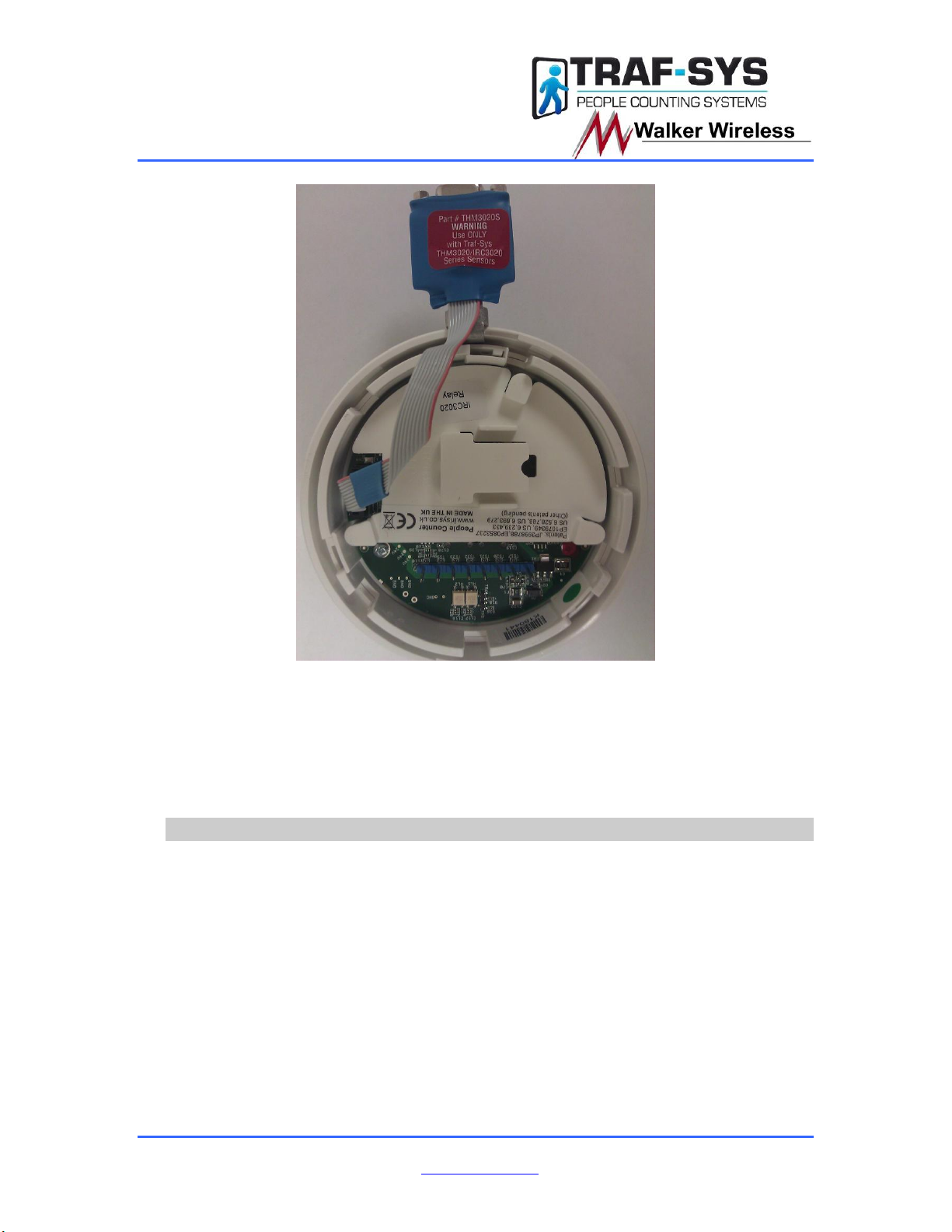
THM3020S Setup Module; see Figure 4 below (do not attempt to use any other
setup module).
A length of serial cable long enough to reach the setup module and the RS-232
port on your PC.
Attaching the Setup Module
1. Remove the sensor from its base. This can be done by twisting the
sensor counter-clockwise to unlock the sensor from the base. After the
sensor is unlocked, pull to remove it from the base.
2. Connect the setup module at the 10 pin female connector inside the
sensor; the 10 pin connector and port are black colored plastic. See
Figure 5 below; also see Figures 6 & 7 for further illustration.

W
Wi
ir
re
el
le
es
ss
s
O
Ov
ve
er
rh
he
ea
ad
d
T
Th
he
er
rm
ma
al
l
S
Se
en
ns
so
or
r
M
Mo
od
de
el
l:
:
T
TH
HM
M3
30
02
20
0
Traf-sys/Walker Wireless, Inc | 190 Industry Drive –Pittsburgh, PA 15275 Page 5 of 18
Ph: 888-815-6568 | Fax: 928-222-7279 | www.trafsys.com
Figure 5
3. Hook the metal part of the setup module just inside the case of the
sensor. This will allow the setup module to slide through a slot on the
base and allow it to be available externally while the sensor is mounted.
See Figure 6 & 7 below.
Figure 6
W
Wi
ir
re
el
le
es
ss
s
O
Ov
ve
er
rh
he
ea
ad
d
T
Th
he
er
rm
ma
al
l
S
Se
en
ns
so
or
r
M
Mo
od
de
el
l:
:
T
TH
HM
M3
30
02
20
0
Traf-sys/Walker Wireless, Inc | 190 Industry Drive –Pittsburgh, PA 15275 Page 6 of 18
Ph: 888-815-6568 | Fax: 928-222-7279 | www.trafsys.com
Figure 7
4. With the setup module in place, attach the sensor to its base again. Line
the sensor back up with its pins on the base and push it into the base.
Twist the sensor clockwise until it locks in to place. It is normal for the fit
to tighter due to the setup module.
5. After the sensor is locked in to place, attached the serial cable to both the
setup module and your laptop PC.
Single Sensor Entrance Calibration
Now that you are connected serially to the sensor with your laptop, please follow
these steps to calibrate the sensor:
1. Launch the Thermal Sensor Configuration Software.
2. Select the appropriate COM port that your serial cable is connected to
and click OK.
3. After the software connects to the sensor, the setup wizard will run and
should tell you that the IDs need to be configured. Press Next and you
will be asked to enter a Comms ID for the sensor with flashing lights. In a
single sensor setup, using “1” will be safe. See Figure 8 below for
illustration.

W
Wi
ir
re
el
le
es
ss
s
O
Ov
ve
er
rh
he
ea
ad
d
T
Th
he
er
rm
ma
al
l
S
Se
en
ns
so
or
r
M
Mo
od
de
el
l:
:
T
TH
HM
M3
30
02
20
0
Traf-sys/Walker Wireless, Inc | 190 Industry Drive –Pittsburgh, PA 15275 Page 7 of 18
Ph: 888-815-6568 | Fax: 928-222-7279 | www.trafsys.com
Figure 8
4. After setting the Comms ID, press Next and the wizard should report that
it has saved your settings successfully.
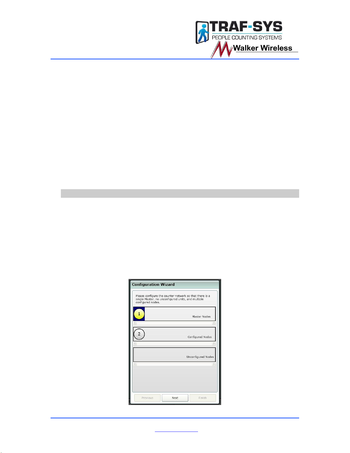
5. Press Next and you will be presented with a screen detailing Master
Nodes, Configured Nodes and Unconfigured Nodes. Click and drag the
red circle for your sensor to the Master Nodes section; the number on the
circle represents its Comms ID. See Figure 9 & 10 below for illustration.
Figure 9
Figure 10
6. Press Next and the wizard should report that it has saved your settings
successfully.

W
Wi
ir
re
el
le
es
ss
s
O
Ov
ve
er
rh
he
ea
ad
d
T
Th
he
er
rm
ma
al
l
S
Se
en
ns
so
or
r
M
Mo
od
de
el
l:
:
T
TH
HM
M3
30
02
20
0
Traf-sys/Walker Wireless, Inc | 190 Industry Drive –Pittsburgh, PA 15275 Page 8 of 18
Ph: 888-815-6568 | Fax: 928-222-7279 | www.trafsys.com
7. Press Next and you will be presented with a confirmation screen showing
the number of sensors and the desired measurement format. See Figure
11 below for an illustration.
Figure 11
8. Confirm that the information displayed is correct and press Next. The
wizard should report that it has saved your settings successfully.
9. Press Next and you will be presented with a screen stating that
configuration is complete. Press Finish to exit the wizard. See Figure 12
below for an illustration.
Figure 12
W
Wi
ir
re
el
le
es
ss
s
O
Ov
ve
er
rh
he
ea
ad
d
T
Th
he
er
rm
ma
al
l
S
Se
en
ns
so
or
r
M
Mo
od
de
el
l:
:
T
TH
HM
M3
30
02
20
0
Traf-sys/Walker Wireless, Inc | 190 Industry Drive –Pittsburgh, PA 15275 Page 9 of 18
Ph: 888-815-6568 | Fax: 928-222-7279 | www.trafsys.com
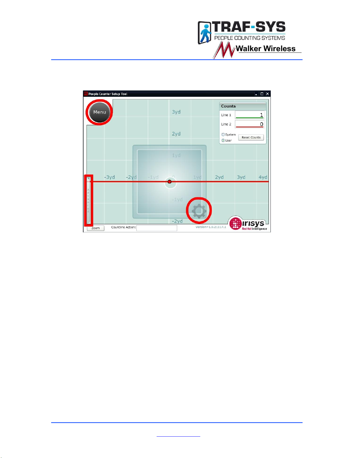
10. In the main screen of the configuration utility, there are a few important
buttons to be mindful of: Menu, Advanced and Device Settings. The
locations of these menus are highlighted in red in Figure 13 below.
Figure 13
11. These three menus expand to reveal sub-menus. In Figure 14 below you
will see the expanded Menu and Advanced while in Figure 15 below you
will see the Device Settings menu (opened by clicking the gear).

W
Wi
ir
re
el
le
es
ss
s
O
Ov
ve
er
rh
he
ea
ad
d
T
Th
he
er
rm
ma
al
l
S
Se
en
ns
so
or
r
M
Mo
od
de
el
l:
:
T
TH
HM
M3
30
02
20
0
Traf-sys/Walker Wireless, Inc | 190 Industry Drive –Pittsburgh, PA 15275 Page 10 of 18
Ph: 888-815-6568 | Fax: 928-222-7279 | www.trafsys.com
Figure 14

W
Wi
ir
re
el
le
es
ss
s
O
Ov
ve
er
rh
he
ea
ad
d
T
Th
he
er
rm
ma
al
l
S
Se
en
ns
so
or
r
M
Mo
od
de
el
l:
:
T
TH
HM
M3
30
02
20
0
Traf-sys/Walker Wireless, Inc | 190 Industry Drive –Pittsburgh, PA 15275 Page 11 of 18
Ph: 888-815-6568 | Fax: 928-222-7279 | www.trafsys.com
Figure 15
12. The sub-menu functions of Menu are as follows:
a. Global –The global settings and errors generated. Global
Settings allow you to set Site information, Date, Time, Time Zone
and Logging Interval. Errors and Warnings displays generated
errors and warnings as well as options to clear and save them.
b. Backup/Restore –You may choose to Backup, Restore or
Compare settings in this menu. Backup saves settings to a file;
Restore takes settings from a file and applies them to the current
sensor while Compare will compare the current settings to a
previously saved file.
c. Lines –This menu allows you to reset the lines to their default
positions or to invert their directions.
d. Run Wizard –Allows you to run the wizard detailed in steps 3-9
again.
e. Permanent All –This sub-menu saves all changes made to be
persistent. This sub-menu should be used frequently and after
any changes are made that should remain.
f. Relay Config –This sub-menu controls which relays the counter
communicates on. The settings in this menu are crucial to the
counter operating properly. See Figure 16 below for the correct

W
Wi
ir
re
el
le
es
ss
s
O
Ov
ve
er
rh
he
ea
ad
d
T
Th
he
er
rm
ma
al
l
S
Se
en
ns
so
or
r
M
Mo
od
de
el
l:
:
T
TH
HM
M3
30
02
20
0
Traf-sys/Walker Wireless, Inc | 190 Industry Drive –Pittsburgh, PA 15275 Page 12 of 18
Ph: 888-815-6568 | Fax: 928-222-7279 | www.trafsys.com
settings to communicate with the Traf-sys/Walker Wireless
Wireless Transmitter devices.
Figure 16
13. The options of the Advanced menu function as follows and an illustration
of correct Advanced menu settings will be show in Figure 17 below:
a. Discrimination Sensitivity –This slider can be adjusted for
accuracy fine tuning.
b. Large Target Couple Counting –When Enabled the sensor
attempts to count large targets (couples) as a single count. This is
typically disabled.
c. Count Mode –Immediate registers counts as lines are crossed.
Deferred registers counts using the last line crossed after the
customer leaves the field of view. Deferred should be used with
Count U-Turns disabled.
d. Deferred Initialization –This option adds an extra step to the
initialization process in an attempt to prevent “ghost” counts from
a floor that is subject to rapid temperature changes. Only use this
option if this specific scenario is observed.
e. Display Path Map Data/Reset Path Mapping –This is mostly for
calibration purposes; it gives a visual representation of where
customers get initialized and their path through the field of view.

W
Wi
ir
re
el
le
es
ss
s
O
Ov
ve
er
rh
he
ea
ad
d
T
Th
he
er
rm
ma
al
l
S
Se
en
ns
so
or
r
M
Mo
od
de
el
l:
:
T
TH
HM
M3
30
02
20
0
Traf-sys/Walker Wireless, Inc | 190 Industry Drive –Pittsburgh, PA 15275 Page 13 of 18
Ph: 888-815-6568 | Fax: 928-222-7279 | www.trafsys.com
Figure 17
14. In the Device Settings menu, you will be able to adjust the Mounting
Height, the X-Y and the Comms ID. The X-Y is the position relative to the
0yd, 0yd point on the graph shown in the background; X controls
horizontal positioning and Y controls vertical positioning. Unit Descriptor,
Device ID, Site Name, Site ID and Locale are optional settings used for
device identification and informational purposes. Refer to Figure 14
above.
15. The last step of sensor calibration is adjusting the line configuration. To
move the line as a whole, click on anywhere on the line that is not a dot.
Clicking on the dots on the line(s) allows you to create anchor points;
anchor points allow you to create a curved or otherwise customized count
line. See Figure 18 below for an illustration.
Figure 18
16. Click the Permanent All sub-menu under Menu to make all settings
persistent.
W
Wi
ir
re
el
le
es
ss
s
O
Ov
ve
er
rh
he
ea
ad
d
T
Th
he
er
rm
ma
al
l
S
Se
en
ns
so
or
r
M
Mo
od
de
el
l:
:
T
TH
HM
M3
30
02
20
0
Traf-sys/Walker Wireless, Inc | 190 Industry Drive –Pittsburgh, PA 15275 Page 14 of 18
Ph: 888-815-6568 | Fax: 928-222-7279 | www.trafsys.com
17. You will now want to test your configuration (this may require the
assistance of additional people). Be sure to test the following scenarios
in addition to “normal” counting:
a. People walking into the store and making a sharp turn. If the
sensor fails to count, you may have to customize the line shape to
better capture this type of behavior.
b. Two or more people entering at the same time, side-by-side. This
may require Large Target Couple Counting being disabled or
enabled based upon customer’s request.
c. People quickly entering and leaving the store. The sensor should
not miss counts of fast moving targets. If the sensor is missing
these counts, the lines will have to be adjusted further inside of
the store to allow more initialization time.
18. Is the sensor counting accurately? If not, adjust the appropriate settings
and repeat step 17. If the sensor is counting accurately, repeat step 16 to
make the settings permanent and you are finished calibrating.
Multiple Sensor Entrance Calibration
Single sensor configuration is remarkably similar to multiple sensor configuration,
just take note of a few key points from below:
1. You will be configuring multiple Comms IDs in step 3. The master sensor
will be Comms ID 1 and the closest sensor on its left (looking out of the
store) will be Comms ID 2. Continue in this fashion incrementing the
Comms ID for each additional sensor. You will be asked to set the
Comms ID for the sensor that is blinking its LED lights one at a time. See
Figure 3 for illustration.
2. You will have 1 Master Node and at least 1 Configured Node in step 5.
You will have to drag and drop the sensors into their necessary roles.
See Figure 19 below.
Figure 19

W
Wi
ir
re
el
le
es
ss
s
O
Ov
ve
er
rh
he
ea
ad
d
T
Th
he
er
rm
ma
al
l
S
Se
en
ns
so
or
r
M
Mo
od
de
el
l:
:
T
TH
HM
M3
30
02
20
0
Traf-sys/Walker Wireless, Inc | 190 Industry Drive –Pittsburgh, PA 15275 Page 15 of 18
Ph: 888-815-6568 | Fax: 928-222-7279 | www.trafsys.com
3. You will be required to configure the Height and X-Y of the sensors during
the wizard process. Measure the appropriate Height value and use the
Traf-sys Sensor Wide Opening Setup Calculator to determine the
necessary X-Y offsets. See Figures 20 & 21 below.
Figure 20
Figure 21
4. There will be one square for each sensor’s field of view and one gear icon
on each field of view to open the Device Settings menu specific to that
device. See Figure 22 below.
Figure 22
5. In step 15, ensure that the configured count lines span across all of the
sensors’ fields of view. As also shown in Figure 22 above.

W
Wi
ir
re
el
le
es
ss
s
O
Ov
ve
er
rh
he
ea
ad
d
T
Th
he
er
rm
ma
al
l
S
Se
en
ns
so
or
r
M
Mo
od
de
el
l:
:
T
TH
HM
M3
30
02
20
0
Traf-sys/Walker Wireless, Inc | 190 Industry Drive –Pittsburgh, PA 15275 Page 16 of 18
Ph: 888-815-6568 | Fax: 928-222-7279 | www.trafsys.com
Troubleshooting
Below are solutions to common problems you may experience with the Wireless
Overhead Thermal Sensor.
Thermal Issues
The Wireless Overhead Thermal Sensors perform at their best in a stable
thermal environment. Situations to avoid:
Locations where machinery or high powered lighting can cause hot spots
of false heat signatures that could be read by the sensor.
Where flooring materials could acquire and store heat via sunlight or high
powered lighting.
Locations where temperatures changes rapidly.
Mounting Issues
Ensure that the field of view is not obstructed by any type of hanging
signage, decorations, fans or lighting.
When mounting sensors to a wall, use the supplied bracket(s) and ensure
that the sensor(s) look directly downward on the detection area.
Do not mount sensors adjacent to vibrating equipment, HVAC vents or
pipes that could cause temperature changes.
Software Issues
The sensor view freeze for a moment or two during use.
oSome serial port drivers buffer data rather than passing it
immediately to the program connected to the COM port. This can
cause a pause during streaming data. This is not a fault of the
sensor, but a feature of the communication port/device. Certain
USB to serial converters may exhibit this problem.
“Device did not reply to ping”
oThis error is most common when using the incorrect COM port or
the sensor(s) are not powered on. Check your COM port and
sensor power and try again.
The COM port I would like to use is not listed.
oCheck other running applications. Certain applications may
require the use of a COM port (virtual or physical) and may lock a
COM port down while the application is running. Exit any
application you feel might be locking up a COM port.
oIf you feel you do not have an application running that would be
locking the COM port, check to make sure that you are using the
correct COM port and that the drivers for the device are correctly
installed.
Safety and Occupancy Issues
The use of Wireless Overhead Thermal Sensors for Occupancy or Safety related
applications is not recommended. No automated people counting solution is
100% accurate, and applications of Occupancy and Safety would almost require

W
Wi
ir
re
el
le
es
ss
s
O
Ov
ve
er
rh
he
ea
ad
d
T
Th
he
er
rm
ma
al
l
S
Se
en
ns
so
or
r
M
Mo
od
de
el
l:
:
T
TH
HM
M3
30
02
20
0
Traf-sys/Walker Wireless, Inc | 190 Industry Drive –Pittsburgh, PA 15275 Page 17 of 18
Ph: 888-815-6568 | Fax: 928-222-7279 | www.trafsys.com
that level of accuracy. If you decide to use the Wireless Overhead Thermal
Sensors for an Occupancy or Safety related application, do so at your own risk
and keep in mind that there is likely to be an error margin involved.
LED Codes
The LED Codes below are for Normal Operation. You should not be concerned
when these occur.
Both LEDs ON: Unit Start
oAs soon as power is applied to the counter it will start a boot up stage, this lasts
approximately 10 seconds and is indicated by both the red and green LEDs on
solidly. Close examination of the LEDs will reveal two small (<100ms) off periods
as different code sections are booted. Once the counter finishes its boot up
stage, it will begin its array stabilization stage.
LEDs Alternate Flashing: Array Stabilization
oAs each counter is a thermal sensing device it must stabilize to its installed
environment. This stabilization stage lasts between 45 seconds and 2 minutes,
dependant on ambient temperature, supply voltage/current etc. During this time,
the two LEDs will alternately flash starting with red ON and green OFF, then
changing to red OFF and green ON, repeating, and changing every second. If
connected via the setup software then an animation will also be displayed.
Occasional LED ‘Blip’: Functioning
oFollowing a successful warm-up period, counters will begin tracking targets and
counting normally. If the counter is not yet configured then it will flash an error
sequence as below. If the counter is configured, then, at this point, counters will
blip both of their LEDs, together, every 5 seconds to indicate correct operation (a
‘Heart beat’). Each LED will also blip independently when a person crosses the
corresponding count line; green LED for Line 1, red LED for Line 2.
Both LEDs Flashing Together Very Quickly: Unit Identification
oAll counters must be configured before they will count correctly –details such as
the height and ground plane position must be entered along with giving each
counter a unique CAN address. Because every counter will have the same
default address when installed, an LED flash sequence is instigated by the
counter setup software to indicate which counter you are currently configuring.
The sequence is both the red and green LEDs flashing together very quickly.
This is essential when configured a network of more than one counter as it is
extremely important to verify the correct counter is being configured by
recognizing this identification sequence.
The LED codes below are for Error Conditions. You should be concerned when
these occur. Error Conditions are noted by the red LED staying on permanently with
a flash sequence coming from the green LED.
Red LED ON, Green LED OFF.
oThis indicates an internal fault which is not resolvable by the user. The only
course of action available is to power down the unit, wait 10 seconds and power
on again. This will rectify the problem in the majority of cases. If this does not
correct the fault then the unit should be returned to your supplier for repair.
Red LED ON, Green LED Flashing Once per Second Repeating
oThis indicates that the counter is has not been configured and is at factory default
address of 127. This is perfectly normal for a new unit and merely indicates that

W
Wi
ir
re
el
le
es
ss
s
O
Ov
ve
er
rh
he
ea
ad
d
T
Th
he
er
rm
ma
al
l
S
Se
en
ns
so
or
r
M
Mo
od
de
el
l:
:
T
TH
HM
M3
30
02
20
0
Traf-sys/Walker Wireless, Inc | 190 Industry Drive –Pittsburgh, PA 15275 Page 18 of 18
Ph: 888-815-6568 | Fax: 928-222-7279 | www.trafsys.com
it requires configuring. All units should be configured as part of the installation
process to ensure accurate count data, and a Comms ID of between 1 and 120
should be entered for each counter. Remember that correct count line positioning
and counter configuration is the key to accurate counting.
Red LED ON, Green LED Flashing Twice per Second Repeating
oThis error can only occur on a master counter; it indicates that the master is not
receiving responses from nodes that were previously connected. This will occur if
a node is removed or disconnected; or if a node has been powered off; or there
is a wiring break between the master and the node(s). This error should not be
confused with the Green LED flashing three times error (below) which can only
occur on a node, although these errors may be seen together in certain
circumstances.
Red LED ON, Green LED Flashing Three Times per Second Repeating
oThis error can only occur on a node unit; it indicates that the node is not been
polled by the master unit. This will occur if the master is removed or
disconnected; or if the master is powered off; or if there is a wiring break between
the master and the node(s). This error should not be confused with the Green
LED flashing twice error (above) which can only occur on a master, although
these errors may be seen together in certain circumstances.
Appendix A: Sensor Base Wiring
Table of contents


