JUMO MAERA S29 SW User manual

40439300T94Z002K000
V6.00/EN/00744209/2020-07-28
JUMO MAERA S29 SW
Titanium or stainless steel level probe
Installation Instructions


Contents
Contents
1 Safety information. . . . . . . . . . . . . . . . . . . . . . . . . . . . . . . . . . . . . . . . . . . . 5
1.1 Safety signs . . . . . . . . . . . . . . . . . . . . . . . . . . . . . . . . . . . . . . . . . . . . . . . . . . . . . . . . . . . . .5
1.1.1 Warning symbols. . . . . . . . . . . . . . . . . . . . . . . . . . . . . . . . . . . . . . . . . . . . . . . . . . . . . . . . . .5
1.1.2 Note symbols . . . . . . . . . . . . . . . . . . . . . . . . . . . . . . . . . . . . . . . . . . . . . . . . . . . . . . . . . . . .5
2 Introduction . . . . . . . . . . . . . . . . . . . . . . . . . . . . . . . . . . . . . . . . . . . . . . . . . 6
3 Identifying the device version . . . . . . . . . . . . . . . . . . . . . . . . . . . . . . . . . . 7
3.1 Nameplate. . . . . . . . . . . . . . . . . . . . . . . . . . . . . . . . . . . . . . . . . . . . . . . . . . . . . . . . . . . . . . .7
3.2 Order details . . . . . . . . . . . . . . . . . . . . . . . . . . . . . . . . . . . . . . . . . . . . . . . . . . . . . . . . . . . . .8
3.3 Accessories. . . . . . . . . . . . . . . . . . . . . . . . . . . . . . . . . . . . . . . . . . . . . . . . . . . . . . . . . . . . . .10
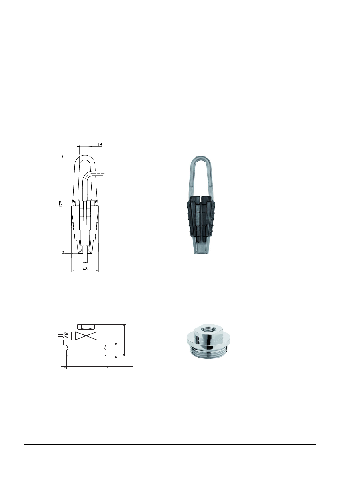
3.3.1 Cable clamp . . . . . . . . . . . . . . . . . . . . . . . . . . . . . . . . . . . . . . . . . . . . . . . . . . . . . . . . . . . . .10
3.3.2 Sealing screw . . . . . . . . . . . . . . . . . . . . . . . . . . . . . . . . . . . . . . . . . . . . . . . . . . . . . . . . . . . .10
3.3.3 Terminal case with pressure compensation element . . . . . . . . . . . . . . . . . . . . . . . . . . . . . .11
3.3.4 Pressure compensation filter for cable . . . . . . . . . . . . . . . . . . . . . . . . . . . . . . . . . . . . . . . . .11
3.3.5 Ex-i repeater power supply / input isolating amplifier . . . . . . . . . . . . . . . . . . . . . . . . . . . . . .12
3.4 Scope of delivery . . . . . . . . . . . . . . . . . . . . . . . . . . . . . . . . . . . . . . . . . . . . . . . . . . . . . . . . .12
3.5 Goods acceptance . . . . . . . . . . . . . . . . . . . . . . . . . . . . . . . . . . . . . . . . . . . . . . . . . . . . . . . .13
3.6 Storage . . . . . . . . . . . . . . . . . . . . . . . . . . . . . . . . . . . . . . . . . . . . . . . . . . . . . . . . . . . . . . . . .13
4 Installation and mounting. . . . . . . . . . . . . . . . . . . . . . . . . . . . . . . . . . . . . . 14
4.1 Dimensions . . . . . . . . . . . . . . . . . . . . . . . . . . . . . . . . . . . . . . . . . . . . . . . . . . . . . . . . . . . . . .17
4.2 Connection diagram . . . . . . . . . . . . . . . . . . . . . . . . . . . . . . . . . . . . . . . . . . . . . . . . . . . . . . .18
5 Technical data . . . . . . . . . . . . . . . . . . . . . . . . . . . . . . . . . . . . . . . . . . . . . . . 19
5.1 General Information . . . . . . . . . . . . . . . . . . . . . . . . . . . . . . . . . . . . . . . . . . . . . . . . . . . . . . .19
5.2 Input . . . . . . . . . . . . . . . . . . . . . . . . . . . . . . . . . . . . . . . . . . . . . . . . . . . . . . . . . . . . . . . . . . .19
5.2.1 Measuring range and accuracy. . . . . . . . . . . . . . . . . . . . . . . . . . . . . . . . . . . . . . . . . . . . . . .19
5.3 Output . . . . . . . . . . . . . . . . . . . . . . . . . . . . . . . . . . . . . . . . . . . . . . . . . . . . . . . . . . . . . . . . . .20
5.4 Electrical data . . . . . . . . . . . . . . . . . . . . . . . . . . . . . . . . . . . . . . . . . . . . . . . . . . . . . . . . . . . .20
5.5 Cable. . . . . . . . . . . . . . . . . . . . . . . . . . . . . . . . . . . . . . . . . . . . . . . . . . . . . . . . . . . . . . . . . . .20
5.6 Mechanical features . . . . . . . . . . . . . . . . . . . . . . . . . . . . . . . . . . . . . . . . . . . . . . . . . . . . . . .21
5.7 Environmental influences . . . . . . . . . . . . . . . . . . . . . . . . . . . . . . . . . . . . . . . . . . . . . . . . . . .21
5.8 Approvals and approval marks . . . . . . . . . . . . . . . . . . . . . . . . . . . . . . . . . . . . . . . . . . . . . . .22
6 Operation, maintenance, and returns . . . . . . . . . . . . . . . . . . . . . . . . . . . . 23
6.1 Operation . . . . . . . . . . . . . . . . . . . . . . . . . . . . . . . . . . . . . . . . . . . . . . . . . . . . . . . . . . . . . . .23
6.2 Maintenance . . . . . . . . . . . . . . . . . . . . . . . . . . . . . . . . . . . . . . . . . . . . . . . . . . . . . . . . . . . . .23
6.3 Returns . . . . . . . . . . . . . . . . . . . . . . . . . . . . . . . . . . . . . . . . . . . . . . . . . . . . . . . . . . . . . . . . .23
7 Malfunctions/faults . . . . . . . . . . . . . . . . . . . . . . . . . . . . . . . . . . . . . . . . . . . 24

Contents
8 Declaration of conformity. . . . . . . . . . . . . . . . . . . . . . . . . . . . . . . . . . . . . . 25
9 Examination certificate . . . . . . . . . . . . . . . . . . . . . . . . . . . . . . . . . . . . . . . . 29
10 IECEx certificate of conformity . . . . . . . . . . . . . . . . . . . . . . . . . . . . . . . . . 33
11 China RoHS . . . . . . . . . . . . . . . . . . . . . . . . . . . . . . . . . . . . . . . . . . . . . . . . . 39

5
1 Safety information
1 Safety informat ion
1.1 Safety signs
1.1.1 Warning symbols
DANGER!
This symbol indicates that personal injury from electrocution may occur if the appropriate precaution-
ary measures are not taken.
WARNING!
This symbol in connection with the signal word indicates that personal injury may occur if the respective
precautionary measures are not carried out.
CAUTION!
This symbol in connection with the signal word indicates that material damage or data loss will occur
if the respective precautionary measures are not taken.
1.1.2 Note symbols
NOTE!
This symbol refers to important information about the product, its handling, or additional benefits.
READ THE DOCUMENTATION!
This symbol, which is attached to the device, indicates that the associated documentation for the de-
vice must be observed. This is necessary to identify the nature of the potential hazard, and to take
measures to prevent it.

6
2 Introduction
2 Introduction
DANGER!
The declaration of conformity, the examination certificate (both found at the end of this operating
manual), and the relevant regulations for sensors and supply units in potentially explosive areas
must be observed!
The sensors must only be operated on intrinsically safe electrical circuits appropriate for the version.
The admissible values can be found in the certificate.
Brief description
The JUMO MAERA S29 SW level probe is used for the continuous hydrostatic level measurement in
ventilated tanks. Measuring is carried out unaffected by electrical medium features or any foam forma-
tion.
Approvals are needed for particular ship building requirements (exclusively titanium) and explosion pro-
tection.
The level probe can be readily used in depths from as low as 1 mWS. The titanium version has been
designed for application in liquids with media containing chlorides. These may be found in ship building,
swimming pools, or water and sewage water management.
The cost-optimized level probe made of titanium or stainless steel with a front-flush membrane offers an
alterative in highly viscous media. The screwable protective cap protects the membrane.
The level probe is equipped with a reverse-polarity protection mechanism, which prevents incorrect po-
larity during startup.
Another benefit to the measuring system is the extensive range of accessories for an optimum design.
Further interesting information can be found in our brochure "Level Probes - Hydrostatic Level Measure-
ment".
Among other things, an optimum design for the measuring system is characterized by the use of a ter-
minal box at the cable end. The correct level probe must be selected on site with regard to the mea-
suring range, version, and specific measurement conditions prior to mounting, installation, and startup!
NOTE!
The specifications provided by the manufacturer are intended as suggestions only, except those relating
to the test series. The decision is to be made by the operator!
CAUTION!
In order to prevent damage to the level probe and to safeguard the process, mounting, installa-
tion, and startup must only be performed by qualified personnel. Personnel must be familiar with
country-specific regulations and be aware of applied standards and directives to prevent bodily
injuries and material damage.
Qualified personnel must have read the operating manual, noted the nameplate, and understood both
so that the instructions can be followed. Modifications and repairs must only be carried out if the operat-
ing manual permits it.
Keep the operating manual at a location that is readily accessible to all users.

7
3 Identifying the device version
3 Identi fying t he device version
3.1 Nameplate
The nameplates (examples) shown below are located on the case of the level probe.
Fig. 3-1 Nameplate (standard)
The serial number (F-Nr.) indicates the production date (year/week) (see example). The Level probe was
therefore produced in the 27th calendar week of 2015.
Fig. 3-2 Nameplate in Ex version
Fig. 3-3 Nameplate in DNV GL version
Fig. 3-4 Nameplate in Ex and DNV GL version
36039 Fulda, GERMANY

3 Identifying the device version
8
3.2 Order details
(1) Basic type
404393 JUMO MAERA S29 SW – Level probe made of titanium or stainless steel
(2) Basic type extension
000 None
062 Shipbuilding approval (only available in titanium version [process connection material 60])
362 Explosion protection
662 Shipbuilding approval and explosion protection (only available in titanium version [process
connection material 60])
999 Special version
(3) Input
301 0 to 1 mH2O
302 0 to 1.6 mH2O
303 0 to 2.5 mH2O
304 0 to 4 mH2O
305 0 to 6 mH2O
306 0 to 10 mH2O
414 0 to 100 mbar relative pressure
415 0 to 160 mbar relative pressure
417 0 to 250 mbar relative pressure
424 0 to 400 mbar relative pressure
419 0 to 600 mbar relative pressure
454 0 to 1 bar relative pressure
455 0 bar to 1.6 bar relative pressure
456 0 to 2.5 bar relative pressure
535 0 to 4 bar sealed gauge
536 0 to 6 bar sealed gauge
537 0 to 10 bar sealed gauge
487 0 bar to 0.6 bar absolute pressure
488 0 to 1 bar absolute pressure
489 0 to 1.6 bar absolute pressure
490 0 to 2.5 bar absolute pressure
491 0 to 4 bar absolute pressure
492 0 to 6 bar absolute pressure
493 0 to 10 bar absolute pressure
997 Special measuring range for sealed gauge
998 Special measuring range for absolute pressurea
999 Special measuring range for relative pressurea
(4) Output
405 4 to 20 mA, 2-wire
(5) Process connection
770 Front-flush process connection with protective cap
(6) Process connection material
20 Stainless steel (only available with PUR cable)
60 Titanium (only available with FEP cable)

9
3 Identifying the device version
Accessories
The accessories are not checked according to DNV GL requirements.
(7) Electrical connection
16 PUR cable, black, shielded (only available in stainless steel version [process connection ma-
terial 20])
25 FEP cable, black, shielded, UV-resistant (only available in titanium version [process connec-
tion material 60])
(8) Length of connecting cableb
002 2 m
005 5 m
010 10 m
015 15 m
020 20 m
030 30 m
040 40 m
050 50 m
060 60 m
070 70 m
080 80 m
090 90 m
100 100 m
(9) Extra codes
000 None
aThe special measuring range is specified in plain text.
bOther cable length available on request.
(1) (2) (3) (4) (5) (6) (7) (8) (9)
Order code / ------/
Order example 404393 / 000 - 417 - 405 - 770 - 60 - 25 - 005 / 000
Description Part no.
Cable clamp 00061389
Sealing screw 00333329
Terminal case with pressure compensation element 00061206
Pressure compensation filter for cable 00382632
Ex-i repeater power supply / input isolating amplifier 00577948

3 Identifying the device version
10
3.3 Accessories
The accessories are not checked according to DNV GL requirements.
3.3.1 Cable clamp
The wire holder, part no. 00061389, holds the probe in the liquid at a defined depth and provides strain
relief. Use of the wire holder ensures that the cable is not deformed in an unacceptable manner.
The wire holder is compatible with all JUMO level probes.
The clamping range is 5.5 to 10.5 mm. The maximum tensile strength is 2.5 kN. The case is made of
hot-dip galvanized steel sheet. The clamping jaws and guide clips are made of fiberglass-reinforced
polyamide. A stainless steel variant is also available upon request.
3.3.2 Sealing screw
For closed containers or water wells with a well head, the cable should be guided through a sealing
screw, part no. 00333329 and secured. The sealing screw is made up of a G 1 1/2" thread and is used
to route the cable.
30
39
14
G1 1/2 A

11
3 Identifying the device version
3.3.3 Terminal case with pressure compensation element
The terminal case, part no. 00061206, is used for secure installation of the level probe cable. The end
of the pressure equalization hose is always protected from deposits and condensation (IP65). The re-
maining distribution can be performed with a standard cable without a pressure equalization hose.
The terminal case should be mounted as close as possible to the medium surface whilst still outside the
medium to ensure the system is implemented cost-effectively and in the best possible way.
3.3.4 Pressure compensation filter for cable
The pressure compensation filter, part no. 00382632, is a breathable filter that ensures aeration and ex-
haust-air ventilation without moisture penetration. It is fitted at the end of the special cable.
(1) Fastening hole

3 Identifying the device version
12
3.3.5 Ex-i repeater power supply / input isolating amplifier
The Ex-i repeater power supply / input isolating amplifier, part no. 00577948, is designed for operating
intrinsically safe transmitters (Ex-i) and mA current sources installed in potentially explosive (Ex) areas.
Two-wire transmitters are supplied with energy and analog 0/4 to 20 mA measured values are transmit-
ted from the Ex-area to the non-Ex-area.
The output of the module can be operated actively or passively.
Further technical data and the relevant safety requirements are available in the operating manual
B 707530.0.
3.4 Scope of delivery
99 17.6
114.5
1 level probe in the ordered version
Installation instructions

13
3 Identifying the device version
3.5 Goods acceptance
1. Check the packaging for possible damage.
2. Check the scope of delivery for completeness and compliance with the order.
3. Check the level probe for possible signs of damage caused during transportation.
CAUTION!
The membrane at the process connection of the level probe must not be damaged.
Otherwise this may result in incorrect measurements or even media leaking.
Do not allow the membrane to come into contact with sharp or hard objects.
3.6 Storage
CAUTION!
The device must be stored in dry, clean conditions and protected against external, mechanical
damage!
The admissible temperatures for storage can be found in the technical data.

14
4 Installation and mounting
4 Instal lation a nd mountin g
DANGER!
The installation and the operation of the level probe must be carried out in accordance with this
operating manual and the applicable regulations and standards.
The supply and output of the level probe must lie in the zone which is not intrinsically safe.
The sensor circuit can be routed to zone 1 in accordance with device group II.
The resulting label is called:
II 2G Ex ib IIC T6...T4 Gb
II 2D Ex ib IIIC T70°C...100°C Db
IECEx Ex ib IIC T6...T4 Gb
IECEx Ex ib IIIC T70°C...T100°C Db
For the maximum permissable temperatures see Technical data.
"Environmental influences ", Page 21
When installing and operating the level probe, ensure that no electrostatic charging can take place.
The membrane of the level probe must not be damaged!
The pressure to be measured must not exceed the admissible overpressure of the level probe even
at pressure peaks.
DANGER!
The relevant regulations must be observed during electrical connection:
- Regulation for the installation of electrical plants in potentially explosive areas
- EC-type examination certificate
The electrical connection must only be carried out by qualified personnel!
The voltage supply must be intrinsically safe and must not exceed the following maximum values:
Ui: DC 28 V
Ii: 100 mA
Pi: 750 mW
Effective inner inductivity L: negligibly small
Effective inner capacity C: ≤ 10.4 nF
Depending on the cable length (L), the following values must be added to the inner capacity or inner
inductivity of the probe:
Effective inner capacity: FEP cable 0.192 nF/m * L, PUR cable 0.188nF/m * L
Effective inner inductivity: FEP cable 0.22 µH/m * L, PUR cable 1.09 µH/m * L
In intrinsically safe electrical circuits, only intrinsically safe, certified measuring devices may be used!
Total capacity/inductivity in accordance of the cable length (L) for selected cable lengths (examples):
FEP cable PUR cable
Cable length [m] Li [µH] Ci [nF] Li [µH] Ci [nF]
2 0.44 10.784 2.18 10.776
5 1.1 11.360 5.45 11.34
10 2.2 12.320 10.9 12.28
20 4.4 14.240 21.8 14.16
50 11 20.000 54.5 19.8
100 22 29.600 109 29.2

15
4 Installation and mounting
(1) Level probe, hanging vertically in the medium
(2) Guide tube for level probe
(3) Cable clamp
(Accessories, part no. 00061389)
(4) Sealing screw
(Accessories, part no. 00333329)
(5) Terminal case with pressure compensation element
(Accessories, part no. 00061206)
(5)
(5)
(3)
(2)
(4)
(1)(1)

4 Installation and mounting
16
CAUTION!
The electrical connection must only be carried out by qualified personnel.
CAUTION!
For setup/operation, the regulations according to the German Hazardous Substances Ordinance
and the German Ordinance of Industrial Safety and Health
(for the relevant device version), as well as this operating manual, are binding.
The maximum admissible ambient temperature of 50 °C must always be observed for the level
probe.
CAUTION!
Install the device in a currentless condition.
CAUTION!
The membrane at the process connection of the level probe must not be damaged.
Otherwise it may result in incorrect measurements or even media leaking.
Do not allow the membrane to come into contact with sharp or hard objects.
NOTE!
Cable assembly
The special cable for the level probe must be fitted such that the pressure compensation in the cable
assembly is not crushed.
The cable end must terminate in a dry room or in a suitable terminal case so that no moisture can pen-
etrate.
A terminal case with a pressure compensation element is recommended for use.
The terminal case should be mounted as close as possible to the surface of the medium while still out-
side the medium.
In addition, the cable should not be routed through damp conditions.
For variations in media, a guide tube should be used that prevents measuring errors in flow caused by
sideways movement and by the level probe hitting the walls of the container.
NOTE!
The level probe must be grounded. To prevent electrolysis, the shielding of the level probe should be set
to the same potential as the other devices found in the medium (pumps, agitators etc.).
NOTE!
Level probes in free-field applications without integrated overvoltage protection must be protected
against electrical discharge.
In addition, it is recommended that external overvoltage protection is used upstream and downstream of
the display or processing unit.

17
4 Installation and mounting
4.1 Dimensions
Titanium Stainless steel
L Cable length according to customer preference L Cable length according to customer preference
(a) Protective cap (a) Protective cap
(b) 5 bore holes for every Ø 5 mm (b) 5 bore holes for every Ø 5 mm

4 Installation and mounting
18
4.2 Connection diagram
Connection example
Current output
Connection Terminal assignment
Cable FEP
(electrical connection 25)
PUR
(electrical connection 16)
4 to 20 mA, 2-wire
Rated voltage supply DC 24 V UB/S+a
0V/S-
White
Gray
White
Brown
Shielding
Caution: Ground the device!
Ground all connected devices (such as
pumps and valves) to the same potential!
Black Black
aThe voltage peaks must not exceed or fall below the specified voltage supply values!
RecorderDisplay
unit
Controller
Level probe
=
+
–
–– –+ + +
p
Power
supply unit
+ –
+
–
=
~

19
5 Technical data
5 Technical d ata
5.1 General Information
5.2 Input
5.2.1 Measuring range and accuracy
Reference conditions According to DIN 16086 and DIN 61298
Measuring principle Piezoresistive sensor with separating membrane
Pressure transfer medium Synthetic oil
Admissible load changes > 10 million, 0 % to 100 % measuring range
Mounting position Vertical/hanging from the cable
Measuring range LinearityaAccuracy at Long-term
stabilitybOverload
capacity
Burst
pressure
20 °Cc10 to 50 °Cd
% MSPe% MSP % MSP % MSP
per year
0 to 1 mH2O 0.2 1.2 1.9 ≤ 0.4 3 4
0 to 1.6 mH2O 0.2 0.8 1.8 4.8 6.4
0 to 2.5 mH2O 0.2 0.8 1.7 ≤ 0.3 7.5 10
0 to 4 mH2O 0.2 0.7 1.7 12 16
0 to 6 mH2O 0.2 0.7 1.6 ≤ 0.2 18 24
0 to 10 mH2O 0.2 0.6 1.3 30 40
0 to 100 mbar relative pressure 0.2 1.2 1.9 ≤ 0.4 0.3 0.4
0 to 160 mbar relative pressure 0.2 0.8 1.8 0.48 0.64
0 to 250 mbar relative pressure 0.2 0.8 1.7 ≤ 0.3 0.75 1
0 to 400 mbar relative pressure 0.2 0.7 1.7 1.2 1.6
0 to 600 mbar relative/absolute
pressure
0.2 0.7 1.6 ≤ 0.2 1.8 2.4
0 to 1 bar relative/absolute pres-
sure
0.2 0.6 1.3 3 4
0 to 1.6 bar relative/absolute pres-
sure
0.25 0.5 1.3 4.8 6.4
0 to 2.5 bar relative/absolute pres-
sure
0.25 0.5 1.2 7.5 10
0 to 4 bar sealed gauge/absolute
pressure
0.25 0.5 1.2 12 16
0 to 6 bar sealed gauge/absolute
pressure
0.25 0.5 1.2 18 24
0 to 10 bar sealed gauge/absolute
pressure
0.25 0.5 1 30 40
aLinearity according to limit point setting
bReference conditions EN 61298-1
cIncludes: linearity, hysteresis, repeatability, deviation from measuring range start (offset), and measuring range end
dIncludes: linearity, hysteresis, repeatability, deviation from measuring range start (offset) and measuring range end,
thermal influences on measuring range start (offset), and measuring span
eMSP = measuring span

5 Technical data
20
5.3 Output
5.4 Electrical data
5.5 Cable
Analog output
Current
Output 405 4 to 20 mA, 2-wire
Step response T90 2ms
Burden
Current
4to20mA, 2-wire R
L≤(U
B-16 V) ÷ 0.022 A (Ω)
Voltage Supply UBa
For basic type extension 404393/
000
DC 16to28V (nominal 24V)
For basic type extension 404393/
062
DC 21 to 24 V (nominal 24 V)
For basic type extension 404393/
362
DC 16to28V (nominal 24V)
For basic type extension 404393/
662
DC 21 to 24 V (nominal 24 V)
Reverse voltage protection Yes
Max. current consumption 23 mA
Electrical circuit SELV
Requirement The device must be equipped with an electrical circuit that meets the require-
ments of EN 61010-1 with regard to „Limited-energy circuits“.
aThe voltage peaks must not exceed the specified voltage supply values!
Cable 6-core, shielded cable
with integrated pressure compensa-
tion hose,
AWG 24 with ferrules
3-core, remote cable
with integrated pressure compensa-
tion hose,
AWG 24 with ferrules
Material
Outer sheath FEP (electrical connection 25) PUR (electrical connection 16)
Compensation hose PA PA
Color Black Black
Outer diameter Approx. 8.4 mm Approx. 7.5 mm
Conductor cross section 0.25 mm20.25 mm2
Bending radius
Moving min. 140 mm min. 75 mm
Fixed min. 70 mm min. 37.5 mm
Tensile force 4000 N -
Mass ≈ 90 g/m -
Admissible temperatures -10 to +70 °C -10 to +70 °C
UV resistance Yes, according to DIN ISO 4892-2 Yes, according to DIN ISO 4892-2
Other manuals for MAERA S29 SW
1
This manual suits for next models
1
Table of contents
Other JUMO Accessories manuals

JUMO
JUMO digiLine CR Series User manual

JUMO
JUMO BlackLine CR 4P User manual

JUMO
JUMO digiLine O-DO S10 User manual

JUMO
JUMO tecLine Series User manual

JUMO
JUMO tecLine ClO2 User manual

JUMO
JUMO tecLine CR-4P User manual

JUMO
JUMO tecLine ClO2 User manual

JUMO
JUMO 201040 User manual

JUMO
JUMO 902454/10 User manual