manuals.online logo
Brands
  1. Home
  2. •
  3. Brands
  4. •
  5. novotechnik
  6. •
  7. Accessories
  8. •
  9. novotechnik LWH Series User manual

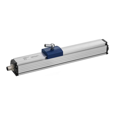
novotechnik LWH Series User manual

LWH Gebrauchsanleitung
LWH User Manual
1Allgemeine Beschreibung
Potentiometrischer Wegaufnehmer für direkte, genaue und
absolute Messung von Wegen bzw. Längen in der Steuerungs-,
Regelungs- und Messtechnik. Technische Daten siehe
www.novotechnik.de/download/Datenblätter => Klick auf LWH
2Sicherheitshinweise
2.1 Bestimmungsgemäße Verwendung
Der Wegaufnehmer wird zu seiner Verwendung in eine Maschine
oder Anlage eingebaut. Er bildet zusammen mit einer Steuerung
(z.B. SPS) ein Wegmesssystem und darf auch nur für diese
Aufgabe eingesetzt werden.
Unbefugte Eingriffe, nicht bestimmungsgemäße Verwendung oder
Nichtbeachtung der Montagehinweise führen zum Verlust von
Gewährleistungs-, Garantie- und Haftungsansprüchen.
2.2 Installation & Inbetriebnahme
Der Wegaufnehmer ist nur von Fachpersonal und unter
Berücksichtigung aller geltenden Sicherheitsvorschriften in Betrieb
zu nehmen. Alle Maßnahmen zum Schutz von Personen und
Sachen bei einem Defekt des Wegaufnehmers müssen vor der
Inbetriebnahme getroffen werden.
Schubstange nicht einfetten!
2.3 Begrenzung Einsatzbereiche
Unsere Produkte sind regelmäßig nicht für Luft- und
Raumfahrtanwendungen zugelassen und dürfen nicht in
kerntechnischen oder militärischen, insbesondere ABC-relevanten
Applikationen verwendet werden.
Weitere Informationen s. unsere AGBs.
3Elektrische Anschlüsse
Falsche Verbindungen und Überspannung können zur
Beschädigung der Bauteile führen. Prüfen Sie deshalb vor dem
Einschalten die Anschlüsse immer sorgfältig.
Die Versorgungsspannung darf nur ausschließlich an die dafür
vorgesehenen Anschlüsse verbunden werden.
Empfohlen:
Die Abschirmung des Anschluss-
kabels ist kundenseitig an
Schutzleiter (PE) anzuschließen.
Sensorseitig soll die Abschirmung
des Anschlusskabels so nah wie
möglich am Gehäuse enden und
nicht am Sensorgehäuse oder den
Steckerkontakten angeschlossen
werden.
Nur wenn der Sensor isoliert
zur Montagefläche eingebaut
ist, darf der Kabelschirm an
Pin 4 angeschlossen werden.
403003030/00 Änderungen vorbehalten / Subject to change without notice 2021/09
1General description
This device is a potentiometric transducer for direct, accurate
measurement of travel in display- or feedback applications.
Technical data see www.novotechnik.de/en/downloads/data-
sheets => Click on LWH
2Safety instructions
2.1 Intended use
The transducer is intended to be installed in a machine or
system. Together with a controller (e.g. PLC) it comprises
a position measuring system and may only be used for
this purpose.
Unauthorized modifications, improper usage or
non-observance of the instructions for installation will result in
the loss of warranty and liability claims.
2.2 Installation & startup
The transducer must be installed by qualified personnel in
consideration of all relevant safety regulations.
All necessary safety measures to protect personnel and
property in case of a transducer defect or failure must be taken
before startup.
Do not lubricate the actuating rod!
2.3 Limitations for application
Our products are regularly not approved for aeronautic or
aerospace applications and are not allowed to be used in
nuclear or military, in particular ABC-relevant applications.
For more information see our Terms and Conditions.
3Electrical connections
Incorrect connections and overvoltage can damage the
components. Please always check the connections carefully
before turning on the system.
The supply voltage must be applied only at the terminals
provided. Recommended:
On customer side, connect cable shielding
to protection earth. On sensor side, the
shielding of the connection cable should end
as close as possible to the housing and it
should not be connected to the sensor
housing or the plug contacts.
The cable shield may only be
connected to pin 4 if the sensor is
installed insulated from the mounting
surface.
3.1 Anschlussbelegung / Terminal assignment
Dargestellte Belegung für ausfahrende Schubstange.
Shown configuration for extended position of the actuating rod.
Seite / page 1
Stecker
Plug
Fallende Kennlinie
Falling
characteristic
Steigende Kennlinie
Rising
characteristic
Pin 1
Anschluss 1: Versorgung
Ub
Connection 1
:Supply
Anschluss 1: GND
Connection 1: GND
Pin 2
Anschluss 2: Signalausgang
Connection 2: Signal
output
Anschluss 2: Signalausgang
Connection 2: Signal
output
Pin 3
Anschluss 3: GND
Connection 3: GND
Anschluss 3: Versorgung
Ub
Connection 3
:Supply
Pin 4
Gehäuse auf PE: Nicht anschließen
Housing
connected to protection earth: do not connect
(Nur bei
isoliertem Einbau: Schirm / Only for insulated installation: Shield)
Bei Verlängerung des Kabels ist auf ausreichende
Schirmdämpfung zu achten. Der PIN 4 darf nicht als
“Schutzleiter“ nach DIN EN 61010 T1 beschaltet werden!
Extension of cable demands a sufficient shielding.
PIN 4 must not be connected as a “PE conductor“ as
prescribed by DIN EN 61010 T1!
Lastfreier Spannungsteiler (Ie ≤ 1 μA)
Voltage divider free of load (Ie ≤ 1 μA)
LWH Gebrauchsanleitung
LWH User Manual
max.
60 Ncm
(85 ozf in)
je Schraube max. 200 Ncm
tighten to max. 200 Ncm (283 ozf in)
Spannklammern
•Nicht an den Flanschen befestigen
(nur am Gehäuseprofil)
•Abstand zueinander ca. 2/3 der
Gehäuselänge
Mounting clamps
•Do not attach to the flanges (solely
to the housing profile)
•2 mounting clamps: distance to
each other approx. 2/3 of the
housing length
403003030/00 Änderungen vorbehalten / Subject to change without notice 2021/09
4 Montagehinweis / Instruction for Installation
5Empfohlenes Zubehör
•Kugelkupplung zur querkraftfreien Ankopplung,
Z-301-M6xM6, Art.Nr. 400058001
•Kugelkupplung zur querkraftfreien Ankopplung,
Z-301-M6xM4, Art.Nr. 400005679
•Kugelgelenkkopf mit Innengewinde M6, Z-G60,
Art.Nr. 400058100
•Messwertumformer für normierte Ausgangssignale
0 … 20 mA, 0 … 10 V, 4 … 20 mA
MUW-200 Art.Nr. 400054101/400054102/400054103
MUW-250 Art.Nr. 400054151/400054152/400054153
5Recommended Accessories
•Ball coupling (to avoid side loads), Z-301-M6xM6,
P/N 400058001
•Ball coupling (to avoid side loads), Z-301-M6xM4,
P/N 400005679
•Pivot head, with internal screw thread M6, Z-G60,
P/N 400058100
•Signal conditioner for standard output signals
0 … 20 mA, 0 … 10 V, 4 … 20 mA
MUW-200 P/N 400054101/400054102/400054103
MUW-250 P/N 400054151/400054152/400054153
Seite / page 2
6Produktidentifikation / Product Identification
Typenschild / Name plate
Querkräfte auf die Schubstange durch
Fluchtungsfehler verringern die mechanische
Lebensdauer und können den Wegaufnehmer zerstören.
Überprüfen Sie vor dem Festschrauben der Schubstange
am Mitnehmer, ob die Schubstange in beiden
Endpositionen („eingefahren“ bzw. „ausgefahren“)
reibungsfrei zentrisch in der Mitnehmerbohrung sitzt.
Empfohlen ist eine zusätzliche Kupplung zur
querkraftfreien Ankopplung (siehe Zubehör).
Side loads on the actuating rod due to
misalignments reduce the mechanical life and can
destroy the transducer. Before screwing the rod to the
driver, check whether the push rod is well centered in the
driver bore in both end positions ("retracted" and
"extended") without friction. An additional coupling is
recommended to avoid side loads (see accessories).
Bestellbezeichnung / Ordering designation
Seriennummer bestehend aus
Fertigungscharge/fortlaufende Nr./Revision
Serial No. consisting of
Batch No./consecutive number/revision
Art.Nr. / Part number
Datum Monat/Jahr MMJJ / Date Month/Year MMYY
4.1 Lieferumfang
Wegaufnehmer mit Zubehör:
2x Spannklammern, 4x Zylinderschrauben M4x20
1x Steckverbindung GDM 3009, 1x Profildichtung GDM 3-16
Empfohlener Einbau
Horizontal: Nut in Gehäuse nach unten
Vertikal: Schubstange nach unten
Recommended Mounting
Horizontal: groove in housing down
Vertical: actuating rod down
4.1 Scope of delivery
Transducer with accessories:
2x mounting clamps, 4x head cap screws M4x20
1x plug connector GDM 3009, 1x sealing gasket GDM 3-16

Other novotechnik Accessories manuals

novotechnik RSX-7900 User manual

novotechnik

novotechnik RSX-7900 User manual

novotechnik RFC 4800 User manual

novotechnik

novotechnik RFC 4800 User manual

novotechnik TP1 CANopen User manual

novotechnik

novotechnik TP1 CANopen User manual

novotechnik RSC-2800 User manual

novotechnik

novotechnik RSC-2800 User manual

novotechnik RSC 3202 User manual

novotechnik

novotechnik RSC 3202 User manual

novotechnik RFC-4800 User manual

novotechnik

novotechnik RFC-4800 User manual

novotechnik RSX-7900 Series User manual

novotechnik

novotechnik RSX-7900 Series User manual

novotechnik RFC-4800 User manual

novotechnik

novotechnik RFC-4800 User manual

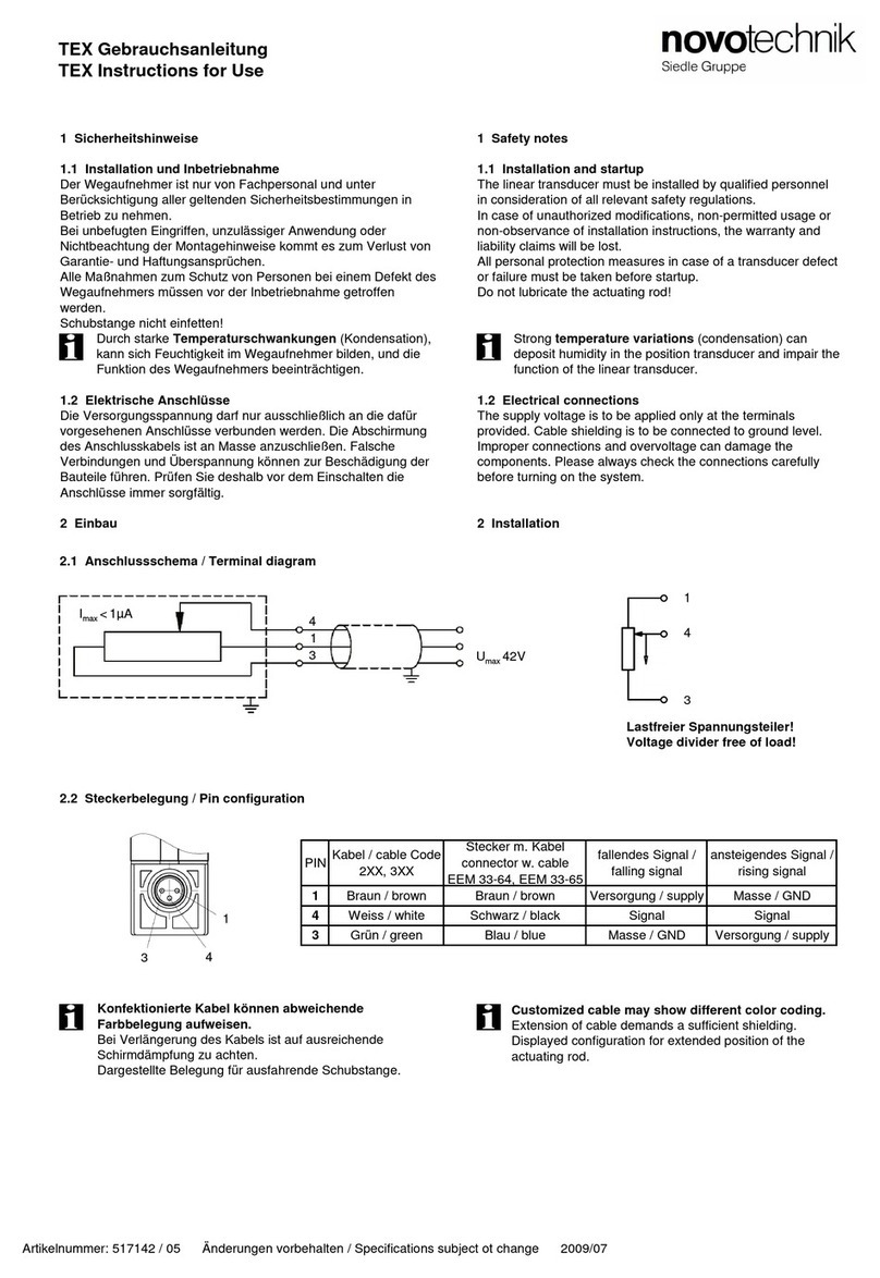
novotechnik TEX series User manual

novotechnik

novotechnik TEX series User manual

Popular Accessories manuals by other brands

4B WDA3V34C Operation manual

4B

4B WDA3V34C Operation manual

Dr.Prepare DP-0AH02 manual

Dr.Prepare

Dr.Prepare DP-0AH02 manual

IFM Electronic O1D102 operating instructions

IFM Electronic

IFM Electronic O1D102 operating instructions

Baumer OADM 13I7580/S35A manual

Baumer

Baumer OADM 13I7580/S35A manual

BUMBER PANBB305-020 Chicago instruction manual

BUMBER

BUMBER PANBB305-020 Chicago instruction manual

Pepperl+Fuchs NCN4-12GM35-N0 instruction manual

Pepperl+Fuchs

Pepperl+Fuchs NCN4-12GM35-N0 instruction manual

JOYSTEK BELL J1 quick start guide

JOYSTEK

JOYSTEK BELL J1 quick start guide

Byron Home Easy HE-302 installation instructions

Byron

Byron Home Easy HE-302 installation instructions

Outwell ECOCOOL LITE Series instruction manual

Outwell

Outwell ECOCOOL LITE Series instruction manual

G21 C&W 33 l manual

G21

G21 C&W 33 l manual

Philips AVENT SOOTHERS manual

Philips AVENT

Philips AVENT SOOTHERS manual

Acecad PenPaper 5x8 user guide

Acecad

Acecad PenPaper 5x8 user guide

Polar Electro GC870-A instruction manual

Polar Electro

Polar Electro GC870-A instruction manual

Orion RKS250F-S Operation manual

Orion

Orion RKS250F-S Operation manual

Q-Waves Quicklink TV Kit Getting started guide

Q-Waves

Q-Waves Quicklink TV Kit Getting started guide

Eaton CurrentWatch EGF Series instructions

Eaton

Eaton CurrentWatch EGF Series instructions

mPTech EMX-320212 user manual

mPTech

mPTech EMX-320212 user manual

SuperFish Garden-Power manual

SuperFish

SuperFish Garden-Power manual

manuals.online logo
manuals.online logoBrands
  • About & Mission
  • Contact us
  • Privacy Policy
  • Terms and Conditions

Copyright 2025 Manuals.Online. All Rights Reserved.