Trail Tech VOYAGER PRO User manual

010-ELV-192
Tech Support: (844) 378-8143
1. MOUNTING THE DOCK:
Voyager Pro’s dock is made to be bolted to the vehicle. Use the
mounting hardware included in your kit or any AMPs style mount
from RAM Mounts rammount.com. Voyager Pro snaps in and out
of the dock for quick removal when not in use.
·
·
2. VEHICLE SENSORS:
The vehicle power connection must be installed. Install the
ignition sensor to enable tach features. Install the engine temp
sensor to enable engine temp features. Voyager Pro comes set
default to “GPS speed.” Optional wheel speed sensors can be
found at trailtech.net.
3. DC POWER:
·
·
·
·
·
4. USER MANUAL:
The user manual is embedded in Voyager Pro.
Open the user manual by pressing the “?” icon.
Look for “User’s Guide” at the bottom of the
main menu or go online to trailtech.net.
5. MAIN SCREENS:
Voyager Pro has several main screens. Press UP and DOWN on the
buttons to move between screens. Press the menu button to open the
main menu. On some screens, like the map screen, press the back button to open a sub-menu with screen-specific options.
6. ENABLE SCREENS:
Voyager Pro has a series of main information screens. Screens can be enabled/disabled in the settings menu. By default, the stop watch and
satellite screens are hidden. Available screens include: the gauge cluster screen with a large speedometer, the tach screen with an animated
tach graph, the map screen, the user definable screen, Bluetooth media screen, the stop watch screen, and the GPS satellites screen.
DC power required. Do not connect Voyager Pro to AC power
except when using the AC wall charger. Connect to a switched
12V DC power source to ensure power to Voyager Pro is cut
when the vehicle is turned off (protects against a dead battery.)
When wired behind the key switch and set to CHARGE-ALWAYS,
charging will begin immediately. Or, use the tach ignition sensor with
the CHARGE-WHEN-RUNNING vehicle profile setting.
Voyager Pro will run approximately one hour on a full battery charge
without external power. Remove it from the vehicle for route planning
and file uploading at your computer.
The below menu options need to be changed when Voyager Pro is
used without a connection to vehicle power:
1. Vehicle Profile > Wake Detection, Speed Source, Charge Mode
2. Maps and GPS Setup > AutoLog Source
NOTE: On some bikes, erratic tach readings can be fixed by wiring the
power directly to the battery instead of behind the key switch.
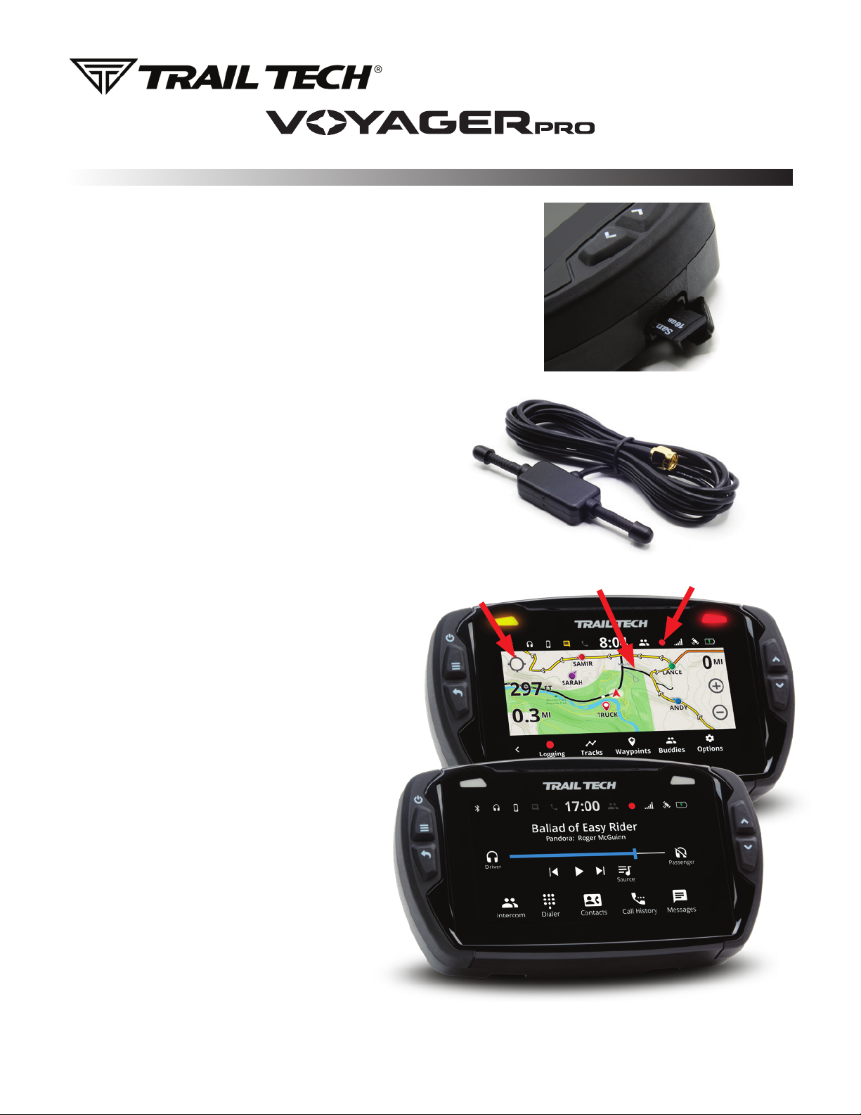
QUICK-START
Press Button to Release
Voyager Pro From Dock
Hydrophobic Vent
GPS Antenna Port
Buddy Tracking
Antenna Port
Allen Wrench
Locking Slot
MicroSD
Card Slot
Sensor
Wires
Press Here on
Map Screen to
Open the
Slideout Menu
Voyager Pro can be locked to the dock using the included 1.5mm
Allen wrench. Turn either way to lock, set to center to unlock.
Add dielectric grease to the dock’s pins to increase lifespan and
add protection against water.
7. MICROSD CARD SLOT:
A MicroSD card (not included in kits) enables transfer of tracks between Voyager Pro and a
PC. During operation, make sure the card slot cover is properly seated to keep debris out.
Tracks saved as GPX files on your computer can be placed on the MicroSD card, then
imported onto Voyager Pro for viewing and route following. This is a great way to share
recorded tracks, or for pre-planning trips. Music files saved on the MicroSD card can be
played from the Media screen.
NOTE: Use exFAT type if you format your MicroSD card on a PC.
8. GPX FILES:
With the map screen’s mini menu you can record, load, and save GPX files.
GPX files are custom made tracks and riding areas that you can follow
yourself, or create and share with the community using RideLeader.com.
9. BUDDY TRACKING:
Buddy Tracking connects multiple Voyager Pros to a private location
tracking network. Once connected to the buddy tracking group you will see
map markers (icons) showing the name and location of all group members.
The technology supports up to 20 riders in a single group.
The mesh network capability increases the comfortable following distance
between you and your buddies. The typical range between buddies is .5 to
1.5 miles, increasing with line of sight and fewer obstructions.
Tap the centering icon in the top left of the map screen to toggle
“Buddy Mode” where the map will always keep buddies on-screen.
Select a “Destination Buddy” to draw a line on the map between
you and your buddy to easily keep track of them.
Note: The provided external V2V antenna is required to use buddy
tracking features.
10. BUDDY BEACON:
When you activate the buddy beacon, your map marker flashes red
on everyone else’s screens. This is not a rescue beacon, it
simply informs the riders in your group that you activated the
beacon. Note: You must be in range for buddies to see your
beacon flashing.
11. BLUETOOTH:
Connect up to two phones and two headsets. The headsets
can function as an intercom between riders. Play songs from
your phone through Voyager Pro to the headset. Receive
phone text notifications and control incoming calls from
Voyager Pro, so you can put your phone away and ride.
12. WARNING INDICATORS:
Set thresholds for max tach and/or temperature. Whenever
Voyager Pro detects the vehicle is exceeding the limit, the
indicator lights will alert you of the situation. Tach warnings
flash, temperature warnings are solid. Set it up under
vehicle profile in the main menu.
QUICK-START
V2V Antenna
Required for
Buddy Tracking
Buddy Group
Centering
Icon
Emergency
Beacon
Recording
Track
MicroSD
Card Slot

POWER AND TACH SENSORS
INSTALLS
POWER CONNECTION:
FOR USE ON 12V REGULATED DC SYSTEMS ONLY!
Connecting to AC power will damage Voyager Pro and void the warranty.
Use a volt meter to confirm nominal 12V DC.
When charging, Voyager Pro MUST BE powered on (avoids draining vehicle battery).
Fuse: Introducing a fuse into the circuit before electronics is always a good idea.
Use a 2 amp fuse with Voyager Pro (not provided).
Vehicles with Regulated DC Power: Voyager Pro requires DC power. Vehicles
with a battery or capacitor and regulator/rectifier produce DC power. Connect
the power wire directly to the vehicle’s 12V battery. Connect the red wire to the
positive(+) battery terminal and the black wire to the negative(-) battery terminal.
Vehicles with AC Power: Use the Voyager Pro AC wall charger, or upgrade to a DC
electrical system. Most carbureted MX bikes put out AC power, but Voyager Pro requires DC power.
Power Wire
SENSORS:
Step 1:
Pull water-seal
down. Wrap
ignition sensor
around coil boot.
Step 2:
Replace
water-seal.
Step 3:
Reinstall
coil boot.
OPTION 2:
If the coil is attached to the spark plug, then wrap the sensor like this:
Water
Seal
TACH IGNITION SENSOR:
Ignition
Sensor
Ignition
Sensor
Wrap
Coil
Spark Plug
The Voyager Pro vehicle sensors
fasten securely to the dock using
waterproof JST connectors.
The connectors are all different
shapes, ensuring you do not plug
a sensor into the wrong connector.
The ignition sensor enables tachometer readings and the
animated bar graph on the tach screen of Voyager Pro.
OPTION 1: (Preferred option for most vehicles.)
Capacitive coupling to spark plug wire:
1.
If required, you may shorten the length of the ignition
sensor. Be very careful when stripping back the black
casing to avoid damaging the inner red wire.
To install ignition sensor wire, wrap the
red part of the sensor wire around the
coil wire 5 times.
Buddy Tracking V2V Antenna
GPS Antenna
Ambient Temperature Sensor
Tach Ignition Sensor
Engine Temperature Sensor
Power Wire
Wheel Sensor

V2V Antenna
Required for
Buddy Tracking
GPS Antenna
TEMPERATURE SENSORS AND ANTENNAS
INSTALLS
TEMPERATURE SENSORS:
V2V AND GPS ANTENNAS:
Most Voyager Pro kits contain a model-specific temperature sensor. Installing the temperature sensor
enables temperature readouts on Voyager Pro’s gauge screens. Alternative sensors are available.
Vehicles cooled with water use sensors to measure the fluid temperature, while air-cooled machines take
the cylinder head’s temperature at the spark plug. The radiator fin sensor is the easiest installation for
water cooled applications.
V2V Antenna:
The vehicle-to-vehicle antenna
sends radio signals between your
vehicle and other vehicles with
Voyager Pro.
The plastic V2V antenna is
designed to be mounted to a
non-metallic surface like a number
plate or shroud, with the ears aimed
vertically, up and down. Higher
up on the vehicle is better, as the
engine and metal panels can block
reception.
GPS Antenna:
The internal GPS antenna is
adequate for normal use. If
there is excessive metal around
the Voyager Pro mounting
location, the reception may be
affected.
An external GPS antenna can
be installed into the dock’s
GPS antenna port to achieve
a better antenna mounting
position. The external GPS
antenna available from Trail
Tech should be mounted flat,
on a non-metallic surface.
Not included in kits.
CVT Sensor Install:
(Continuously Variable Transmission)
200ºF+ Warning: CVT Belt wear occurs
more rapidly at high temperatures.
Let the belt cool down to increase lifespan.
Drill 13/64” (5mm) hole in
hard plastic CVT exhaust.
Thread sensor into hole.
The sensor threads are M6x10.
Use high temp RTV (silicone
gasket sealer) to seal case cover.
Not included in kit.
1.
2.
3.
Radiator Fin
Sensor Installation:
Conrm correct size.
Apply thermal grease to
maximize heat transfer.
Carefully press sensor
between radiator ns.
1.
2.
3.
Radiator Hose
Sensor Installation:
Drain uid.
Measure inner diameter
of hose before cutting.
Mark hose.
Cut hose.
Slide on hose clamps.
Install sensor & tighten
hose clamps.
1.
2.
3.
4.
5.
6.
Mark
& Cut
Tighten
CHT Cylinder Head
Spark Plug
Sensor Installation:
Remove crush
washer from
spark plug.
Replace with
temperature
sensor.
Re-install
spark plug.
1.
2.
3.
Sensor replaces
crush washer
If the in sensor is too large,
le it to size rather than
forcing it into the radiator.
Screw
Sensor Installation:
1.
2.
Remove radiator pressure
relief bolt.
Replace with temperature
sensor.

MOUNTING OPTIONS
INSTALLS
UTV SURFACE MOUNT:
For UTV’s and vehicles with a
dashboard, this flat surface RAM mount
is good solution. We recommend two
composite RAM ball bases and a short
arm as shown. We suggest locating
Voyager Pro in the middle of the vehicle
where both the driver and passenger
have visibility.
Note: If bolting to a plastic
surface, use a backing plate
on the backside for a much
more stable installation.
HANDLEBAR MOUNTS:
Voyager Pro plastic handlebar mounting hardware kit for 7/8” and
1-1/8” bars. Patented mount design has two points of articulation,
enabling a wide variety
of mounting positions.
Made from special
high strength materials
to withstand the
rigors of powersports.
Comes with four
M4x14mm screws to
attach the Voyager
Pro dock. Included in
Voyager Pro kits.
HANDLEBAR
CENTER
MOUNT:
Voyager Pro Center Mount for
1-1/8” bars, a strong upgrade
for your Voyager Pro mounting.
Aluminum CNC with matte black
anodized finish.
Works with split bar clamps, like
on KTM and Husqvarna.Comes
with four M4x14mm screws to
attach the Voyager Pro dock.
Find on trailtech.net.
SUCTION CUP
MOUNT:
RAM mount for windshields or
smooth surfaces. Consists of a
3.3” diameter RAM suction cup
twist lock base connected to a
diamond base with ball, short arm
and a composite base with the
AMPs hole pattern for attaching
the Voyager Pro dock. Included in
the Voyager Pro automotive kit
(922-124.)
UTV ROPS MOUNT:
RAM mount for mounting Voyager Pro to a steering column or UTV
roll cage. Safely conceals the strap clamp in a compact housing, so
you won’t have to worry about exposed sharp edges or unwanted
loosening.
The preferred location to install this mount is on the roll cage bar.
Even though it also works with most steering columns, it may block
the built-in speedometer in the dash.
Consists of RAM rail base, short arm and a composite base with the
AMPs hole pattern. Comes with four M4x14mm screws to attach the
Voyager Pro dock.
Included in the Voyager Pro UTV kit (922-125.)
Flat Surface
Mount
026-FS
Steering Column/
ROPS Mount
026-SC
Handlebar Mounts
9200-1000
Center Mount
026-OEB9
Suction Cup
026-SUC
Other manuals for VOYAGER PRO
2
Table of contents
Other Trail Tech GPS manuals


