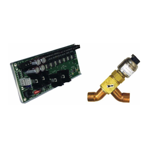
Train-Tech RL1 User manual

Instruction manual contents:
• Overview with Connections and Troubleshooting:!! ! ! ! ! ! page 1
• Relay control using Track Sensors or Sensor Signals (can be powered by DCC or DC)!page 2
• Relay control using DCC Accessory Commands (DCC only)!! ! ! ! page 3
• Relay control using Mimic Switches (can be powered by DCC or DC)!! ! ! page 4
•Connecting to the relays – hints and tips on how to connect devices to be controlled !! page 5
•Automatic Train Control for multiple trains using a Sensor Signal or Track Sensor!! page 6
•Automatic Train Control for a single short stop using a Sensor Signal or Track Sensor!! page 7
• ABC Braking for DCC Automatic Train Control!! ! ! ! ! ! page 7
Caution - only ever connect with all power turned off and ensure you never touch any
other connections or components otherwise permanent damage will result.
RL1 Relay Controller
1!
Please handle carefully & read these instructions fully before using!!
Overview
The Train-Tech RL1 Relay Controller incorporates two built in relays to switch high power low voltage
loads controlled by Track Sensors, Sensor Signals, Mimic Switches or DCC Accessory commands.
Please read these instructions carefully.
Document Ref D779766/2 DP300420 ©Train-Tech 2020
Troubleshooting
This product is designed to be easy to connect and use but here are a few tips which may help should you
have problems following installation. Remember only ever wire and install with all power turned OFF.
•If wishing to control Relays using DCC Accessory addresses you must first set your DCC controller to
accessory command mode to set up and use it – refer to your controller manufacturers instructions.
•Use adequate thickness cables to connect Relay outputs to the models it is controlling.
•Please note that it is normal for the base of the Relay Controller to get very warm – do not remove the
foam base which is fitted for protection and allow space for adequate airflow.
•Note that you should include appropriate suppression particularly for trains, motors and solenoids using
capacitors, chokes etc to prevent interference to other train control products and domestic appliances
•
•ABC braking technology is complex and setting up CV commands and wiring Diode modules correctly
varies between DCC decoder manufacturers, so refer to their detailed instructions for specific decoders.
Learn/Set
Button
Sensor Mimic
Control Inputs
Power in
DC/DCC
Mounting Holes
(3mm max)
Connections
Underside – Foam pad
This protects connections
and provides insulation
from circuit board heat.
DO NOT REMOVE PAD!
S M LEARN DCC/DC S M
NO COM NC NO COM NC
CH1
CH2
LED
indicator
Channel 1
Relay contacts
Channel 2
Relay contacts
Sensor Mimic
Control Inputs

2
•Relay Control using Track Sensors/Sensor Signals (DC/DCC)
You can use a Track Sensor or Sensor Signal to change a relay when a train passes it.
Just a single wire is needed to link between one of the Sinput of the Relay Controller and the
centre socket of a Track Sensor or Sensor Signal – solid core 1/0.6mm wire is ideal as it just plugs
into the sensor/signal and is as supplied by Train-Tech (WP2/WP3) or model or electrical stores.
The Relay Controller and Track Sensors/Sensor Signals can be powered either by DCC or smooth
DC – see the pictures at the bottom of this page to show how to power the Track Sensors/Signals.
Track Sensors can be used at the same time as Mimic Switch control and DCC accessory control -
priority is the device which sent the most recent control command, ie Track Sensor, Mimic or DCC.
POWER
Power the Track Sensor or Sensor
Signal and the Relay Controller
from the same power supply;
either Track DCC or connect it to
12–16V maximum smooth DC.
Direction
of Trains
SENSOR
POWER
see below
SENSOR
POWER
see below
Optional 2nd
Sensor/Signal
Link wire to optional second Track Sensor or Signal
Track Sensor or Sensor Signal
Power by sliding sensor into track – for DCC
If using DCC you
can power the
sensor from the
track by sliding
these two ‘fingers’
under the rails into
the slots in some
types of track, like
a power clip.
ensure good
connections!
Track Sensor or
Sensor Signal
To power using
DC or DCC solder
2 wires into the
holes shown
Power by wiring to sensor – for DC or DCC
Track Sensor or
Sensor Signal
Cut off the two fingers
with sharp cutters
where marked – – -
Using Track Sensors with N Gauge: The Track sensor is
designed primarily for OO gauge track, however we have
found that it can be used with N gauge if the fingers are
removed, some parts of sleepers trimmed and the sensor is
placed close to (but not touching) the rail.
RL1 Relay
Controller
Power in
DC/DCC
Using one Track Sensor or Sensor Signal the relay will close as soon as the train passes it and
then open again about 7 seconds after the last part of the train has passed the sensor. However if
you use a second Track Sensor/Signal and link it to the first as shown above, then the relay will
close as the train passes the first sensor but not open until the train passes the second sensor, so
in this way you can make something operate while a train is located in a particular section of track.
S M LEARN DCC/DC S M
NO COM NC NO COM NC
CH1
CH2
Can be connected to
a Mimic Switch for
simultaneous control
Relay 2 outputs Relay 1 outputs (see page 5)

3
•Relay control using DCC accessory commands (DCC only)
The Relay Controller can be used to switch relatively high power low voltage devices using
standard DCC accessory commands.
The two relay outputs can each be given a unique DCC accessory address so that they can be
turned on or off using a single command from your DCC controller. Accessory commands are
different from the Loco commands used to control the trains, but most DCC controllers can also
control accessories*. Controllers usually have a DCC accessory mode button marked ACC or have
an icon of a point or similar – find out by referring to your particular controllers instruction manual.
Connections
Wiring is easy, with just two wire connections from your standard DCC track output to the DCC/DC
terminals on the RL1. Connect whatever you are controlling to the Relay contact outputs (page 5).
Controlling the relays using DCC Accessory commands
You can control a relay on the Relay Controller by assigning it an Accessory address and sending
a command. Note that unlike loco commands, Accessory commands have just two ‘states’ usually
referred to as on or off (or on some controllers 1 or 2 or left or right direction).
To assign an accessory address to each of your Relays connect the RL1 to the standard DCC
track power output, set your DCC controller to Accessory control mode and turn on DCC power.
To set up the address for Relay channel 1 (CH1):
• Enter the address you want to give to Relay CH1
•Press the Learn button on the relay controller once – the red LED should single flash
•Press your DCC controller on or off button (or 1 or 2, or left or right)
The red LED will then stop flashing and you can control Relay CH1 using that accessory address
To set up the address for Relay channel 2 (CH2):
• Enter the address you want to give to Relay CH2
•Press the Learn button on the relay controller Twice – the red LED should double flash
•Press your DCC controller on or off button (or 1 or 2, or left or right)
The red LED will then stop flashing and you can control Relay CH2 using that accessory address
Note that you can give more than one device the same DCC accessory address, so for example
you can change a relay and a point or signal using one command at a single address.
DCC accessory control can be used at the same time as Mimic Switch and Track Sensor control -
priority is the device which sent the most recent control command, ie Track Sensor, Mimic or DCC.
*NB Note that a few DCC controllers are not able to control DCC accessories, including the basic
Bachmann EZ command controller supplied in some Bachmann train sets and the Gaugemaster
Prodigy Express, both of which can only control DCC Locos. Refer to your controller instructions.
Relay 2 outputs
Power in
DC/DCC
Relay 1 outputs (see page 5)
Learn Button
S M LEARN DCC/DC S M
NO COM NC NO COM NC
CH1
CH2
LED
Can be connected to
Track Sensor or
Mimic Switch for
simultaneous control
Can be connected to
Track Sensor or
Mimic Switch for
simultaneous control
RL1 Relay
Controller

4
• Relay control using a Mimic switch (DC or DCC)
•
The relays in the Relay Controller can be controlled using Train-Tech Mimic Switches to manually
control a relay; the dual colour red/green LED (LED A) supplied with each Mimic will also light and
indicate the state of the relay.
Mimic Switches can be used in addition to Track Sensor control and DCC accessory control
previously described and so can be used to manually override a relay. Control priority is given to the
device which sent the most recent control signal, ie Track Sensor, Mimic Switch or DCC command.
Wiring is easy with just a single wire linking the M terminal of the Mimic Switch to the M terminal of
the Relay Controller.
The Mimic Switch should be powered by the same DC or DCC power as the Relay controller.
Mimic Switch
Power supply
DCC or 12–16
volts maximum
smooth DC
Tip
Note that a useful feature is that if a Mimic Switch is connected to an RL1 as well as a Track Sensor
or Sensor Signal to the same relay, then the occupancy LED (LED B) on the Mimic Switch will light
as a Train passes the sensor (see Mimic switch instructions for more details).
S M LEARN DCC/DC S M
NO COM NC NO COM NC
CH1
CH2
Relay 2 outputs Relay 1 outputs (see page 5)
Can be connected to
a Track Sensor or
Sensor Signal for
simultaneous control

5
• Connecting to the Relay output contacts
The RL1 contains two relays, each of which has single pole changeover contacts to control
motors, lamps etc. The contacts can be used to switch up to 24 volts AC or DC at up to 3 amps.
They should be connected in the same way as you would connect a switch, so wired in series with
(in between) power and whatever you are controlling. The drawing below shows the internal relay
contacts inside the RL1 so that you can see how they relate to a switch. The common (COM)
terminal is the contact which moves and the other two terminals are Normally Open (NO), which
means it is only connected to the COM terminal when the relay is activated, and Normally Closed
(NC), which means it is connected to COM when the relay is not activated.
These type of relay (or switch) contacts are called changeover contacts.
• How does a relay work?
A relay is an electrically activated switch
and consists of a coil of wire wrapped
around a metal bar which forms an
electro-magnet or solenoid which, when
energised, moves an electrical contact
to make or break connection with other
contacts. The main benefits of a relay
are that you can use relatively low
power to energise the coil to control
much higher amounts of power, and
also the output terminals are not
electrically connected to the coil input
terminals and so are safely isolated.
S M LEARN DCC / DC S M
NO COM NC NO COM NC
CH1
CH2
Relay 2 (shown
not activated)
Relay 1 (shown
not activated)
S M LEARN DCC/DC S M
NO COM NC NO COM NC
CH1
CH2
S M LEARN DCC/DC S M
NO COM NC NO COM NC
CH1
CH2
Motor,
Lamp,
Solenoid,
etc
AC or DC power
to suit what is
being controlled
• Simple on-off control using the Relay Controller
Connect
these inputs
to DC or DCC
power and
optionally
also to Mimic
Switches or
Track
Sensors to
control the
relays.
Control this via the relay by DCC
accessory commands, Track
Sensors or Mimic switch
• Reversing a DC Train or motor using the Relay Controller
DC
Motor
Connect
these inputs
to DC or DCC
power and
optionally
also to Mimic
Switches or
Track
Sensors to
control the
relays.
12 volts DC
This example shows how you can use both relays
in an RL1 to control the on-off power & direction
of a DC motor – this could be the motor in a train
on an automatic shuttle line for example.
If both relays are off or both are on then the motor
will not turn, but switching either output on will
make motor run in one direction or the other.
This could be controlled by track sensors or DCC.
Note that you may need to use suppressors particularly on motors and
solenoids to prevent interference (these are usually fitted to loco motors)
Note that you may need to use suppressors particularly on motors and
solenoids to prevent interference (these are usually fitted to loco motors)
eg Loco

Sensor Signal
(or track sensor)
•Automatic Train Control for multiple trains (DCC or DC)
On the real railway train drivers have to drive to signals and stop at red and although that is also
nice to do on model railways, most people operate their layouts by themselves and have too much
to do driving trains, changing points and standing back and enjoy it!
Train-Tech’s Sensor Signals (or the SC100 Signal controller for automating existing signals or N
gauge etc) are Automatic and work just like the real railway’s Block Section signalling, normally
showing green but changing to red as soon as a train goes past it and staying red until the train
clears the following signal after the next section. However a red signal cannot stop the train on its
own, but by making an isolated track section just before the Sensor signal and linking the signal to a
Relay Controller to control the track section, trains approaching a red signal will stop until the signal
displays green and makes it safe for the model train to proceed into the next section. In this way you
can have a completely automatic model railway with several trains ‘chasing’ each other but never
colliding as they will be held at least a section away by Sensor Signals working with Relays.
Although this sounds complex, it is actually relatively easy to wire thanks to the technology already
in the Sensor signals and Layout Link, which is a single wire control system which links the signals
and relays together. The illustration below shows how to wire two Sensor Signals and two stop
sections to an RL1 to stop trains when they come up against a red signal. This shows just two stop
sections, but it can be scaled to many more in the same way, either end to end or continuous ovals.
6
Direction
of Train
To cut the rails use a Dremel type saw, track cutters or use isolating tracks.
You can use plastic isolating fishplates to join cut rails neatly and smoothly.
Stop Section
Rails are cut to make an Isolated track section before
each signal which is long enough to take the longest
locomotive and so stop it before the signal if it is red
S M LEARN DCC/DC S M
NO COM NC NO COM NC
CH1
CH2
Sensor Signal
(or track sensor)
A
B
A
B
to other signalsother signals
The Sensor Signals are all powered and linked together as normal (explained in signal instructions)
and a single wire from each Signal goes to the S input of the Relay Controller. A Relay Controller
has two relays, so each can control two track sections and each isolated track section is connected
to the Normally Closed (NC) relay output so that when the relay is not activated by the signal (ie
when signal is red) it connects power to the track section as normal. You can use this system on
either analogue DC or DCC track power layouts, but note that the loco’s will come to a sudden stop
once they are are fully inside an isolated track section unless they are DCC-ABC decoder fitted
locos and optional ABC diode modules are fitted as shown – see page 7 for more on ABC braking.
Manual override
Trains can be released manually from the stop section using either Mimic switches connected to the
‘M’ input of the RL1 (page 4) or DCC commands to override the RL1 (page 3) or Sensor Signal.
Semaphores Although not strictly prototypical to the real railway, it is possible to control Dapol
Semaphore signals using Track Sensors with Train-Tech SC300/400 modules and to stop trains in a
similar way to the colour light signals by also connecting the Track Sensor output to RL1 as above.
POWER
Optional ABC
Diode Module
Interference suppression
Note that you should include
appropriate suppression
particularly for trains, motors
and solenoids using
capacitors and chokes to
prevent interference
Optional ABC
Diode Module
POWER
Power the Sensor Signal or Track
Sensor and the Relay Controller
from the same power supply;
either Track DCC or connect it to
12—16V maximum smooth DC.
See bottom of page 2 for power
connections to Sensor Signals etc

7
• Automatic Train Control for a single short stop (DCC or DC)
This project shows how you can use one Train-Tech Automatic Sensor Signal (or a Track Sensor)
to stop a train for a short time just after a signal at a platform etc, then automatically set off again.
A Sensor signal is normally green until a train goes past it, when it will turn red and stay red until 7
seconds after the last part of the train passes. In this project as the signal turns red the relay will
operate and isolate the stop section from power so that when the locomotive or driving car passes
into the isolated section it will stop* and wait until the signal leaves red when it will start again.
Note that while 7 seconds is quite a short time & is not adjustable (because the time is fixed in the
signal), the stop can also be controlled by an optional Mimic Switch or DCC accessory command
to keep the relay on and the section isolated – on DCC the signal can also be manually overidden.
The project works on DC or DCC layouts, though note that if using DCC Sound locos they will
stop and the sound go off suddenly unless they are fitted with ABC braking chips (see below).
Care should be taken when planning the length of the stop section and its distance from the signal
because the isolated section will only stop the train for 7 seconds after it has passed the signal.
POWER
Power the Sensor Signal or Track
Sensor and the Relay Controller
from the same power supply;
either Track DCC or connect it to
12–16V maximum smooth DC.
See bottom of page 2 for power
connections to Sensor Signals etc
Direction
of Train
Sensor Signal
(or track sensor)
RL1 Relay
Controller
Power in
DC/DCC
S M LEARN DCC/DC S M
NO COM NC NO COM NC
CH1
CH2
Can be
connected to a
Mimic Switch
for control of
stop section
Stop Section
Rails are cut to make an
Isolated track section
To cut the rails use a Dremel type saw, track cutters or use isolating tracks.
You can use plastic isolating fishplates to join cut rails neatly and smoothly.
• Smooth stopping for DCC locos with ABC Braking* (DCC)
Some DCC loco decoders have technology called ‘ABC’ built in which enables locomotives to
slow down gradually and stop when it comes to a section of track with an ABC diode module fitted
in series with the DCC power, and these can be used with the Automatic Train Control projects for
RL1 so that trains slow down instead of suddenly stopping. However note that the ABC diode
modules only work with DCC locos fitted with configured ABC decoders and none-ABC chip fitted
locos will not slow down or stop in isolated sections where ABC diode modules are installed. The
ABC diode modules are made by a number of manufacturers including Train-Tech (part ref ABC1).
Always switch power off
when making connections!
Note that ABC loco decoders
must be configured using the
instructions from the decoder
manufacturer. Some require ABC
diode modules to be connected a
particular way round, so be sure
to carefully follow instructions.
A B
Optional ABC Diode
Module (see below)
A B
The Train-Tech ABC Diode
modules have 2 pairs of terminals,
A and B. They are internally
connected together so either may
be used. Connect the track section
break to A or B terminals and RL1
output to the other terminals.
Other Train-Tech Controllers manuals
Popular Controllers manuals by other brands

JuiceGoose
JuiceGoose CQ Series owner's manual
Global American Inc.
Global American Inc. 3307620 Version 1.0 user manual
AutomationDirect
AutomationDirect CLICK PLUS PLC manual
Pegasus Astro
Pegasus Astro ULTIMATE POWERBOX V3 product manual

PTZOptics
PTZOptics PT20XSE-PRODUCER-JOY4 user guide
KEBCO
KEBCO COMBIVERT F6 Instructions for use

