TrakPower TK955 User manual
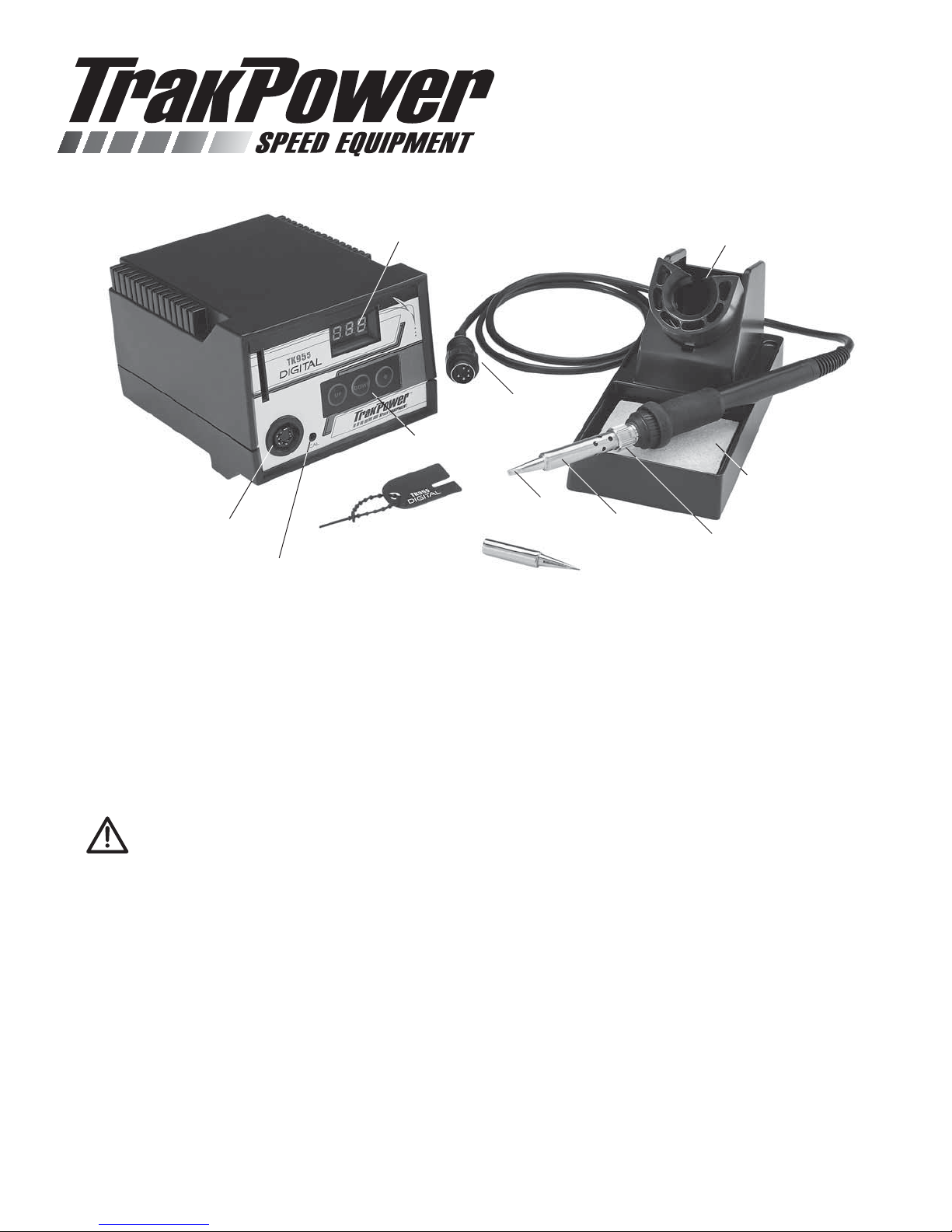
IRON HOLDER
TIP RETAINER NUT
CLEANING SPONGE
CHISEL TIP
TIP RETAINER
CALIBRATION ADJUSTMENT
SECURITY KEY
PENCIL TIP
TEMPERATURE CONTROLS
DIGITAL DISPLAY
RETAINING NUT
CORD
RECEPTACLE
™
For best results read the entire manual before operating.
TK955 Digital
Soldering Station
Packing List
●TK-955 Soldering Station ●Iron Holder with Sponge
●Soldering Iron with Tip ●2 Security Keys
●Pencil Tip
Precautions
CAUTION: When the power is on, the tip temperature is between 200°C / 400°F and 480° C / 899°F. Since
mishandling may lead to burns or fire, be sure to comply with the following precautions:
•
Do not touch the metallic parts while operating.
•
Always store the iron in the holder when not in use.
•
Do not use the product near flammable items.
•
Advise other people in the work area that the unit can reach a very high temperature and should be considered
potentially dangerous.
•
Turn the power off while taking breaks and when you are finished using it.
•
Before replacing parts or storing the unit, turn the power off and allow the unit to cool to room temperature.
To prevent damage to the unit and ensure a safe working environment, be sure to comply with the following precautions:
•
Do not use the unit for applications other than soldering.
•
Do not hit the soldering iron against the work bench or other objects to shake off residual solder.
•
Do not modify the unit.
•
Use only genuine replacement parts.
•
Do not bend or damage the security key. Should the key become bent, do not force it into the station.
•
Do not allow the unit to become wet or use the unit when your hands are wet.
•
The soldering process will produce smoke. Make sure the area is well ventilated.
Setup and Operation
1. Connect the soldering iron cord assembly to the receptacle. Secure it by rotating the retaining clip clock-wise.
2. Install the desired tip.
3. Saturate the cleaning sponge with water and place it into the holder.
4. Plug the power cord into a grounded outlet.
5. Turn the power switch on. The heater LED will flicker when the temperature has stabilized. The heater LED is located
in the lower right corner of the display.
Setting the Temperature
CAUTION: Be sure to insert the slotted end of the security key into the key slot. While setting the
temperature, the heating element is off.
1. Insert the key into the key slot in the station. The left-most digit (the 100’s digit) in the display will flash. This indicates
the station is in the temperature setting mode and the 100’s digit can be adjusted.
2. Select the desired value of the 100’s digit. Pressing the “UP” or “DOWN” button will change the displayed value.
3. Press the “*” button when the desired value is displayed. This will cause the middle digit (the 10’s digit) in the display
to flash.
4. Pressing the “UP” or “DOWN” button will change the displayed value.
5. Press the “*” button when the desired value is displayed.This will cause the right digit (the 1’s digit) in the display to flash.
6. Pressing the “UP” or “DOWN” button will change the displayed value.
7. Pressing the “*” button does the following actions:
a) Enters the temperature setting into the internal memory.
b) Displays the temperature setting.
c) Starts the heater control.
Security Key
If the key is left in the unit, push and hold the “*” button for more than 1 second. The soldering station goes into temperature
setting mode. Pressing the “*” button for less than 1 second will display the present temperature setting for two seconds and
then return to showing the tip temperature.
Removing the security key will not allow the temperature setting to be changed until the key is reinserted.
Parameter Adjustments
The following parameters can be adjusted while in parameter input mode:
A. °C or °F temperature display.
B. Heater error temperature tolerance.
C. Display room temperature for tip calibration.
Parameter Input Mode
1. Turn off the power switch.
2. Press and hold the “UP” and “DOWN” buttons simultaneously.
3. Turn on the power switch.
4. Continue holding down the “UP” and “DOWN” buttons until display shows 1C or 1F. The station is in parameter
input mode.

5. To change temperature units: Use the “UP” and “DOWN” buttons to change between 1C (for Celsius) or 1F (for
Fahrenheit).
6. When desired unit is displayed, press
the “*” button. The station is now in
heater error temperature tolerance
setting. The temperature will be
displayed with the 100’s digit flashing.
7. To change heater error temperature
tolerance, use the same steps in
“Setting the Temperature” section. The temperature setting for the heater error temperature tolerance must be within
the following range. For °C: 30-150° C. For °F: 60-300° F. If a temperature value outside of this range is selected, the
display will return to flashing the 100’s digit. If this happens, re-enter a temperature within the range.
8. After entering the heater error temperature tolerance, the station will display the room temperature compensation value.
To calibrate the tip use the following steps:
A. Allow the soldering station to cool to room temperature
for one hour.
B. Use a thermometer to measure the room temperature.
C. Use a small regular or a cross point screw driver to adjust
the screw marked “CAL” on the soldering station until
the display indicates the room temperature measured
by the thermometer.
9. Press the “*” button to exit the parameter input mode. The soldering temperature will be displayed for two seconds,
after which power will be supplied to the heater and normal operation mode will begin.
Use
1. For the longest tip life, select the lowest temperature required to properly do the job.
2. Once the iron has reached the desired temperature, wipe the tip on the cleaning sponge to remove any build up.
3. Once the tip has been cleaned, coat it with a thin layer of fresh solder. This is called tinning the tip.
4. Use the smallest amount of solder needed to properly do the job. Extra solder requires extra heat and the chance of
overheating the item being soldered.
5. When finished, wipe the tip clean and tin it with fresh solder. Turn off iron and let it cool before storing.
Care
1. Clean the tip regularly using the cleaning sponge. This removes impurities and reduces the oxidation that can limit
heat transfer.
2. After every 4 hours of use: Allow the iron to cool. Remove the tip holder retaining nut and wipe the threads clean with
a dry rag. Re-install the retaining nut finger tight. This will reduce the oxidation build-up that could cause the nut to
seize onto the retainer.
3. Do not leave the unit turned on for long periods of time when not in use. Prolonged heating can degrade the tip even
when not in use.
4. Always keep the cleaning sponge moist when using the iron. If the sponge is dry, it will not clean the tip properly and
can burn.
5. To help reduce oxidation, always wipe and tin the tip with fresh solder when you’re done soldering.
6. Check the condition of the tip.Tip life can vary greatly depending on the temperature used. Replace the tip if it becomes
deformed or if solder will no longer stick to it.
NOTE: Heater Error Temperature Tolerance: If power is being sent to the
soldering iron and the tip temperature falls below the heater error temperature
tolerance, the temperature display will flash. This indicates a possible heater
malfunction. Example: The temperature is set to 400°C and the heater error
temperature tolerance is set to 50. If the tip temperature drops below 350°C
while power is being sent to soldering iron, the display will begin to flash,
indicating a possible heater malfunction.
NOTE: Room Temperature Compensation
Value: The room temperature compensation value
is the measured temperature of the soldering iron
tip.This value is used to calibrate the tip temperature
when the soldering iron is replaced.
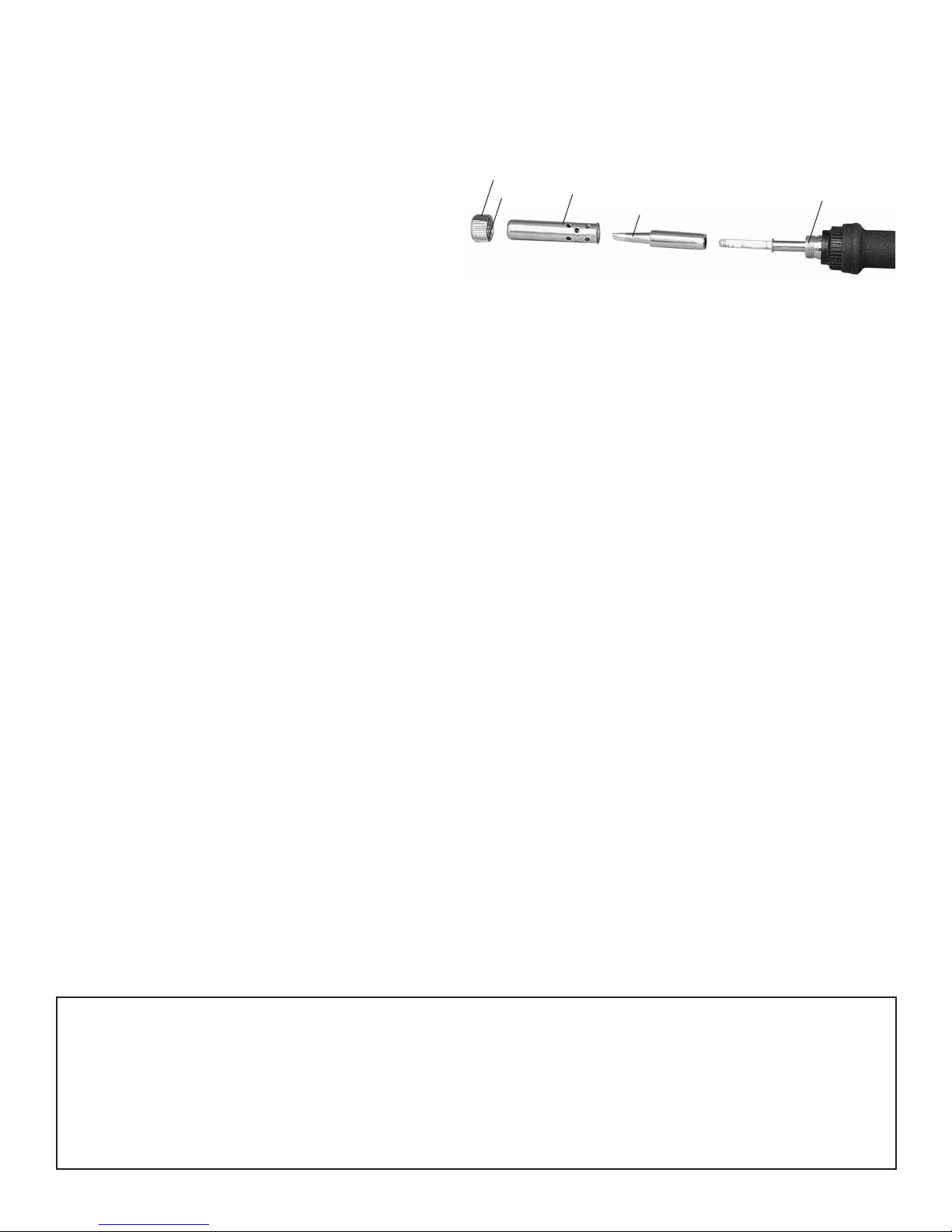
Replacing the Tip
1. Turn off, unplug, and allow the iron to cool to room temperature.
2. Loosen and remove the retaining nut.
3. Remove the tip holder.
4. Remove and dispose of the old tip.
5. Wipe the threaded section of the iron and the
retaining nut with a dry rag.
6. Install the new tip, holder, and retaining nut. The nut should only be tightened to finger tight.
7. Plug in and turn on the iron. When it reaches the desired temperature, wipe the new tip clean on the cleaning sponge
and tin it with fresh solder.
Error Messages
- - - = System Error
After the power has been turned on, the system checks the memory and the programs. If an abnormality is found, - - -
will be displayed and all operation will be completely stopped.
S – E = Sensor Error
If there is a possibility of a failure in the sensor or anywhere in the sensor circuit, S – E will be displayed and power to
the soldering iron will be cut off.
Flashing of temperature display = Heater Error
If power is being sent to the soldering iron and the tip temperature falls below the heater error temperature tolerance, the
temperature display will flash. This indicates a possible heater malfunction. Example: The temperature is set to 400°C
and the heater error temperature tolerance is set to 50. If the tip temperature drops below 350°C while power is being
sent to soldering iron, the display will begin to flash indicating a possible heater malfunction.
Parts
Replacement
TKPR0960 TrakPower Replacement 908 Iron
TKPR0965 TrakPower A1042 Sponge
TKPR0968 TrakPower Chisel Tip 3.2 mm
TKPR0969 TrakPower Chisel Tip 2.4 mm
TKPR0970 TrakPower Pencil Tip 1.0 mm
Optional
TKPR0975 TrakPower Rosin Core Lead Free Silver Solder 15 g
TKPR0976 TrakPower Rosin Core Silver Solder 100 g
TKPR1015 TrakPower Cleaning Wire with Holder
TrakPower warrants this product to be free from defects in materials and workmanship for a period of 5 years on the base unit and 1 year on the
iron handle from the date of purchase. During that period, TrakPower will, at its option, repair or replace without service charge any product deemed
defective due to those causes.You will be required to provide proof of purchase (invoice or receipt).This warranty does not cover damage caused by
abuse, misuse, alteration or accident. If there is damage stemming from these causes within the stated warranty period, TrakPower will, at its option,
repair or replace it for a service charge not greater than 50% of its then current retail list price. Be sure to include your daytime telephone number in
case we need to contact you about your repair. This warranty gives you specific rights.You may also have other rights, which vary from state to state.
For service on your TrakPower
product, warranty or non-warranty,
send it post-paid and insured to:
HOBBY SERVICES
3002 N. Apollo Drive Suite 1
Champaign, IL 61822
(217) 398-0007
www.hobbyservices@hobbico.com
TKPR0955
TIP
RETAINING NUT
THREADS
THREADS TIP HOLDER
Table of contents


