TEF 9202 T3/IP66 Ex ENCLOSURE HEATER USER MANUAL
INTRODUCTION
Thank you for purchasing this product!
For installation, maintenance and assurance of a long life
of this product, please follow this manual.
CONTENT IN BOX
The product is fully assembled, and ready for installation.
SAFETY PRECAUTIONS
SPECIAL CONDITION FOR SAFE USE
Tranberg heaters type TEF 9202 are not suitable for use in
Zone 0 hazardous areas. Changes made to the product not
conforming to the certificate, or failing to use the product
according to the user manual and relevant regulations
may lead to a fire or explosion risk, as well as risk of
overheating of equipment, burns and electric shock. The
manufacturer is under no circumstances responsible for
any injury or damage caused by such activities.
Installation, testing and maintenance shall be performed
by qualified personnel. Equipment shall be securely
disconnected from voltage elsewhere before any install,
testing or maintenance activities are performed on the
heater.
INSTALLATION INSTRUCTION
Only qualified personnel are allowed to perform installation
and maintenance tasks to this product.
The enclosure heater is ready for installation when leaving
the production facilities of Tranberg AS. If the content has
any defects or is not complete, file a claim to the manufac-
turer immediately.
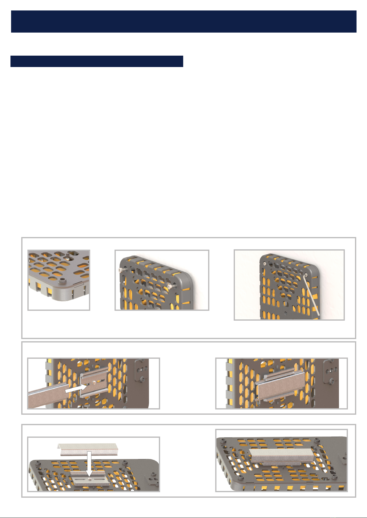
Mounting:
The 9202 Enclosure Heater must be mounted and fastened
through mounting holes at rear side of heater by means of
M5 screws/bolts. All screws must be firmly tightened to se-
cure the heater.
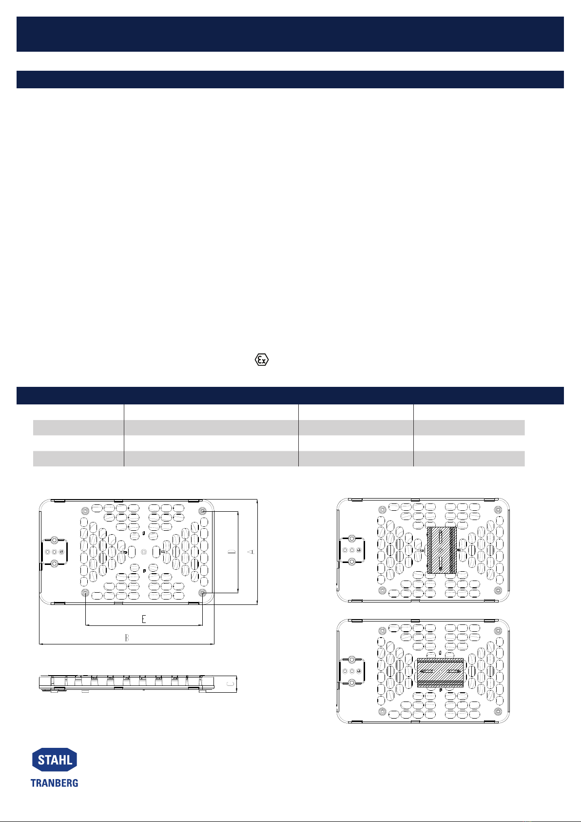
All measures for mounting are shown ion
the last page of this manual.
Special conditions for safe use (as stated in the rel-
evant certificates):
• The heaters with permanently connected unterminat-
ed flying lead cable need an appropriate protection of
the free end of the cable (for example terminated in an
Ex e junction box).
• The heaters with thermostat shall be connected to
a circuit breaker with rated current max. 16A and a
breaking capacity of min. 1500A.
• The supply circuit shall include an electrical protection
device according to IEC/EN 60079-30-1 CL 4.3
• Enclosure heaters of type TEF9206, 9208, 9209 and
TEF 9202 0XX shall be installed inside an enclosure
with IP min. IP66 (this clause is not applicable for TEF
9207 and TEF 9202 2XX).
Additional Conditions for heaters type TEF 9202:
• Potential electrostatic charging hazard – For cleaning
use mist cloth only! No solvent.
• If DIN-rail bracket is used for mounting on a rail, this
shall be earthed.
Tranberg heaters type
TEF 9202 hold the following certificates:
ATEX: Presafe 18ATEX12634X
IECEx: IECEx PRE 18.0037X
The certificates are issued in based on the following
standards:
EN 60079-0:2012/A11:2013
EN 60079-7:2015
EN 60079-18:2015
EN 60079-30-1:2007
IEC 60079-0:2011
IEC 60079-7:2015
IEC 60079-18:2014
IEC 60079-30-1:2007
APPROVALS & CERTIFICATES
INSTALLATION REQUIREMENTS
The heater supply circuit shall be protected against earth
fault and short circuit currents in accordance with IEC/EN
60079-30-1 (For version 2015/2017 clause 4.3). For heaters
without thermostat, the circuit breaker shall be selected to
fit the installation and sufficiently protect the “flying lead”
2,5mm² cable in the heater.
When the heater is not installed inside a certified hazardous
area enclosure (for example Ex p, Ex e, Ex d etc.) the flying
lead cable shall be protected from mechanical damage.
The TEF 9202 heater series shall only be used inside a
certified hazardous area enclosure with IP min. IP54. The
TEF 9202 heater series are suitable for use in any enclosed
space (room, skid, uncertified enclosure, container, storage
cabinet etc.). The use of heaters in open air is not recom-
mended. If internal procedures demand isolation/dielectric
testing of the heaters, this should be done with DC voltage
of max 2550V DC.
DISPOSAL
The heaters shall be disposed of according to company
and national regulations. The heaters are considered elec-
trical equipment waste (EE waste).