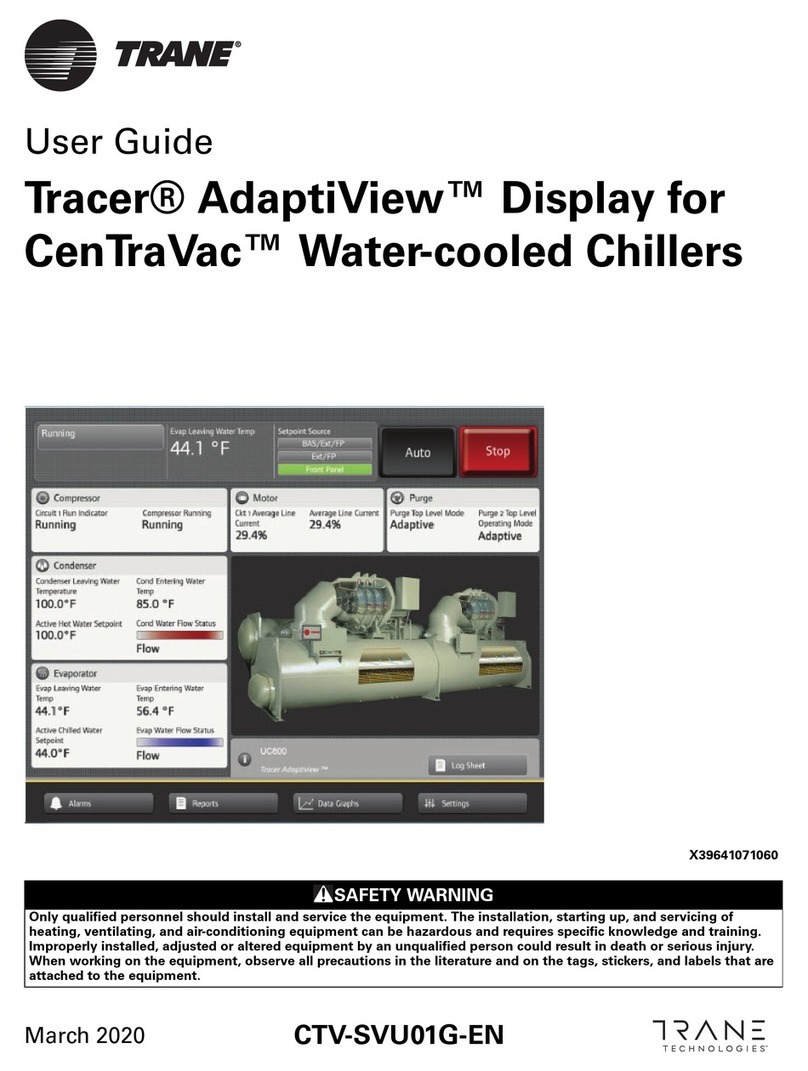
Trane Tracer AdaptiView User manual

Operations Guide
Tracer AdaptiView™Display
for Water-Cooled CenTraVac™Chillers
X39641071-020
March 2008 CTV-SVU01B-EN

Copyright
© 2008 Trane All rights reserved
This document and the information in it are the property of Trane and may not be used
or reproduced in whole or in part, without the written permission of Trane. Trane reserves
the right to revise this publication at any time and to make changes to its content without
obligation to notify any person of such revision or change.
Trademarks
AdaptiView, CenTraVac, Trane, the Trane logo, and Tracer are trademarks of Trane in the
United States and other countries. All trademarks referenced in this document are the
trademarks of their respective owners.

CTV-SVU01B-EN • Tracer AdaptiView Display Operations Guide 3
Contents
Introduction . . . . . . . . . . . . . . . . . . . . . . . . . . . . . . . . . . . . . . . . . . . . . . . . . . . . . . 5
Equipment Description . . . . . . . . . . . . . . . . . . . . . . . . . . . . . . . . . . . . . . . . . . . 5
Touchscreen Guidelines . . . . . . . . . . . . . . . . . . . . . . . . . . . . . . . . . . . . . . . . . . 6
Reference Sources . . . . . . . . . . . . . . . . . . . . . . . . . . . . . . . . . . . . . . . . . . . . . . 6
Screen Overview . . . . . . . . . . . . . . . . . . . . . . . . . . . . . . . . . . . . . . . . . . . . . . . . 7
Chiller Status Area . . . . . . . . . . . . . . . . . . . . . . . . . . . . . . . . . . . . . . . . . . . . 8
Main Display Area/Home Screen . . . . . . . . . . . . . . . . . . . . . . . . . . . . . . . . . 9
Component Screens . . . . . . . . . . . . . . . . . . . . . . . . . . . . . . . . . . . . . . . . . . 12
Main Menu Area . . . . . . . . . . . . . . . . . . . . . . . . . . . . . . . . . . . . . . . . . . . . . 13
Stopping/Restarting Chiller Operation . . . . . . . . . . . . . . . . . . . . . . . . . . . . . . . . 14
Stopping the Chiller . . . . . . . . . . . . . . . . . . . . . . . . . . . . . . . . . . . . . . . . . . . . 14
Restarting the Chiller . . . . . . . . . . . . . . . . . . . . . . . . . . . . . . . . . . . . . . . . . . . 15
Alarms . . . . . . . . . . . . . . . . . . . . . . . . . . . . . . . . . . . . . . . . . . . . . . . . . . . . . . . . . . 16
Viewing the Alarms Screen . . . . . . . . . . . . . . . . . . . . . . . . . . . . . . . . . . . . . . 16
Understanding Alarm Icons . . . . . . . . . . . . . . . . . . . . . . . . . . . . . . . . . . . . 17
Viewing Active and Historic Alarms . . . . . . . . . . . . . . . . . . . . . . . . . . . . . 17
Sorting Alarms . . . . . . . . . . . . . . . . . . . . . . . . . . . . . . . . . . . . . . . . . . . . . . 17
Resetting Alarms . . . . . . . . . . . . . . . . . . . . . . . . . . . . . . . . . . . . . . . . . . . . . . . 18
Other Alarm Indicators . . . . . . . . . . . . . . . . . . . . . . . . . . . . . . . . . . . . . . . . . . 18
Reports . . . . . . . . . . . . . . . . . . . . . . . . . . . . . . . . . . . . . . . . . . . . . . . . . . . . . . . . . 19
Viewing the Reports Screen . . . . . . . . . . . . . . . . . . . . . . . . . . . . . . . . . . . . . . 19
Viewing the Log Sheet . . . . . . . . . . . . . . . . . . . . . . . . . . . . . . . . . . . . . . . . . . 20
Viewing the ASHRAE Chiller Log . . . . . . . . . . . . . . . . . . . . . . . . . . . . . . . . . . 20
Creating and Viewing a Custom Report . . . . . . . . . . . . . . . . . . . . . . . . . . . . 20
Editing a Custom Report . . . . . . . . . . . . . . . . . . . . . . . . . . . . . . . . . . . . . . . . . 22
Viewing Unit Information (About This Chiller) . . . . . . . . . . . . . . . . . . . . . . . 22
Viewing Chiller Operating Modes . . . . . . . . . . . . . . . . . . . . . . . . . . . . . . . . . 23
Viewing Purge Operating Modes . . . . . . . . . . . . . . . . . . . . . . . . . . . . . . . . . . 26
Data Graphs . . . . . . . . . . . . . . . . . . . . . . . . . . . . . . . . . . . . . . . . . . . . . . . . . . . . . 27
Viewing the Data Graphs Screen . . . . . . . . . . . . . . . . . . . . . . . . . . . . . . . . . . 27
Viewing Data Graphs . . . . . . . . . . . . . . . . . . . . . . . . . . . . . . . . . . . . . . . . . . . 28
Changing the Scales on Data Graphs . . . . . . . . . . . . . . . . . . . . . . . . . . . . . . 28
Creating Custom Data Graphs . . . . . . . . . . . . . . . . . . . . . . . . . . . . . . . . . . . . 30
Creating a custom data graph from a default data graph . . . . . . . . . . . . 30
Creating a custom data graph with no previously defined data graph
points . . . . . . . . . . . . . . . . . . . . . . . . . . . . . . . . . . . . . . . . . . . . . . . . . . . . . . 32
Editing Custom Data Graphs . . . . . . . . . . . . . . . . . . . . . . . . . . . . . . . . . . . . . 33

4CTV-SVU01B-EN • Tracer AdaptiView Display Operations Guide
Contents
Deleting a Custom Data Graph . . . . . . . . . . . . . . . . . . . . . . . . . . . . . . . . . . . 33
Equipment Settings . . . . . . . . . . . . . . . . . . . . . . . . . . . . . . . . . . . . . . . . . . . . . . . 34
Viewing the Settings Screen . . . . . . . . . . . . . . . . . . . . . . . . . . . . . . . . . . . . . 34
Viewing and Changing Equipment Settings . . . . . . . . . . . . . . . . . . . . . . . . . 35
Chiller Setting . . . . . . . . . . . . . . . . . . . . . . . . . . . . . . . . . . . . . . . . . . . . . . . . . 38
Setpoint Sources . . . . . . . . . . . . . . . . . . . . . . . . . . . . . . . . . . . . . . . . . . . . . . . 39
Setpoint Source Arbitration . . . . . . . . . . . . . . . . . . . . . . . . . . . . . . . . . . . . 39
Changing the Setpoint Source . . . . . . . . . . . . . . . . . . . . . . . . . . . . . . . . . . 40
Feature Settings . . . . . . . . . . . . . . . . . . . . . . . . . . . . . . . . . . . . . . . . . . . . . . . 42
Chilled Water Reset . . . . . . . . . . . . . . . . . . . . . . . . . . . . . . . . . . . . . . . . . . . . . 42
Purge Settings . . . . . . . . . . . . . . . . . . . . . . . . . . . . . . . . . . . . . . . . . . . . . . . . . 43
Manual Control Settings . . . . . . . . . . . . . . . . . . . . . . . . . . . . . . . . . . . . . . . . . 44
Display Settings . . . . . . . . . . . . . . . . . . . . . . . . . . . . . . . . . . . . . . . . . . . . . . . . . . 47
Viewing the Settings Screen . . . . . . . . . . . . . . . . . . . . . . . . . . . . . . . . . . . . . 47
Viewing and Changing Display Preferences . . . . . . . . . . . . . . . . . . . . . . . . . 48
Viewing and Changing the Language Preference . . . . . . . . . . . . . . . . . . . . 50
Viewing and Changing Date and Time Preferences . . . . . . . . . . . . . . . . . . . 52
Cleaning the Display . . . . . . . . . . . . . . . . . . . . . . . . . . . . . . . . . . . . . . . . . . . . 53
Security Settings . . . . . . . . . . . . . . . . . . . . . . . . . . . . . . . . . . . . . . . . . . . . . . . . . 54
Viewing the Settings Screen . . . . . . . . . . . . . . . . . . . . . . . . . . . . . . . . . . . . . 54
Disabling/Enabling Security . . . . . . . . . . . . . . . . . . . . . . . . . . . . . . . . . . . . . . 55
Logging In . . . . . . . . . . . . . . . . . . . . . . . . . . . . . . . . . . . . . . . . . . . . . . . . . . . . 56
Logging Out . . . . . . . . . . . . . . . . . . . . . . . . . . . . . . . . . . . . . . . . . . . . . . . . . . . 57
Troubleshooting . . . . . . . . . . . . . . . . . . . . . . . . . . . . . . . . . . . . . . . . . . . . . . . . . . 58
Appendix A: Component Screen Data . . . . . . . . . . . . . . . . . . . . . . . . . . . . . . . . 59
Appendix B: Reports . . . . . . . . . . . . . . . . . . . . . . . . . . . . . . . . . . . . . . . . . . . . . . 62
Appendix C: Data Graph Data Points . . . . . . . . . . . . . . . . . . . . . . . . . . . . . . . . . 69
Data Points Used in Default Data Graphs . . . . . . . . . . . . . . . . . . . . . . . . . . . 69
Data Points Available to Include in Custom Data Graphs . . . . . . . . . . . . . . 72

CTV-SVU01B-EN • Tracer AdaptiView Display Operations Guide 5
Introduction
The Tracer AdaptiView™ display provides a means for viewing data and for making
operational changes on CenTraVac™ chiller models CVHE, CVHF, and CVHG.
The purpose of this guide is to assist you in using the Tracer AdaptiView display. The
guide describes how to access the screens and the types of information that appear on
the screens.
Equipment Description
The basic equipment features of the Tracer AdaptiView display are described here.
Hardware
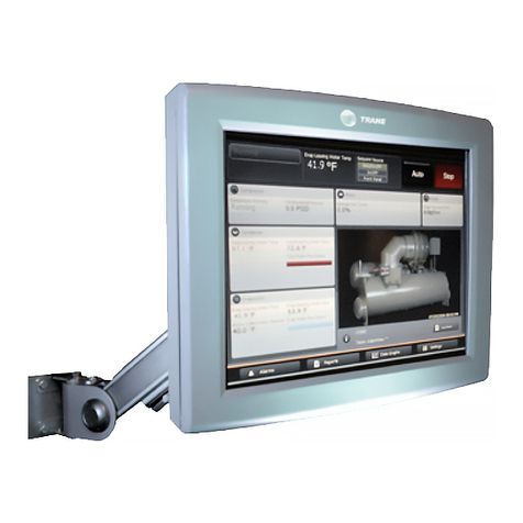
The Tracer AdaptiView display is mounted on or near the chiller control panel. It can be
attached to the chiller by an arm that can extend 11 inches. Five pivot points enable full
articulation as described in the following specifications and in the illustration:
• Two horizontal pivots points 90º right or left (180º total)
• Two vertical pivots points: 90º degrees up or down (180º total)
• Rotation: 135º clockwise and 135º counterclockwise (270º total)

6Tracer AdaptiView Display Operations Guide • CTV-SVU01B-EN
Introduction
Screen characteristics
The 12.1-inch VGA touch-sensitive color screen displays data in either inches and pounds
(IP) or standard international (SI) units, and in one of twenty-four available languages.
Animated color graphics indicate the status of the chiller and its components.
AC power
The Tracer AdaptiView display receives AC power through its power cable, which is
connected to the Tracer UC800 controller. The Tracer UC800 controller must be powered
On.
Communication
A separate cable provides communication between the Tracer AdaptiView display and
the Tracer UC800 controller. Alarms are communicated immediately upon detection.
Touchscreen Guidelines
The touch screen registers the downward pressure of a touch. Light, quick, yet deliberate
presses are most effective. Touching with more pressure has no effect.
Recommended tools to use: finger, thumb, pencil eraser. Do not use a pen or pencil point,
or any other sharp or pointed object that might scratch the screen surface.
If you apply and hold pressure at more than one point, the touch screen registers only
the first touch. For example, if you press a finger on an area of the screen that is not touch
sensitive, pressing a sensitive area with another finger will not register.
Holding on to the screen with your hand can cause unintended navigation, such as from
thumb or palm pressure.
Reference Sources
Additional information on CenTraVac chillers with AdaptiView control can be found in
these documents:
•CVHE, CVHF, CVHG Water-Cooled CenTraVac™ Chillers with Tracer AdaptiView™
Control Installation, Operation, and Maintenance Guide (CVHE-SVX02A-EN)
•CDHF, CDHG Water-Cooled CenTraVac™ Chillers with Tracer AdaptiView™ Control
Installation, Operation, and Maintenance Guide (CDHF-SVX01A-EN)
•EarthWise™ Purge System with Tracer AdaptiView™ Control Operation and
Maintenance Guide (PRGD-SVX01A-EN)
•Diagnostics Descriptions, Troubleshooting Tables, and Control Component Overview
for Water-Cooled CenTraVac™ Chillers with Tracer AdaptiView™ Control (CTV-
SVD03A-EN)
•Tracer™ TU Service Tool Programming Guide for Water-Cooled CenTraVac™ Chillers
with Tracer AdaptiView™ Control (CTV-SVP02A-EN)
•Tracer™ TU Service Tool Getting Started Guide (TTU-SVN01A-EN)

CTV-SVU01B-EN • Tracer AdaptiView Display Operations Guide 7
Introduction
Screen Overview
The touch-sensitive areas of the Tracer AdaptiView display screen are described in detail
in this section.
In Figure 1, three areas are identified, which correspond to the following subsections:
1. “Chiller Status Area,” p. 8
2. “Main Display Area/Home Screen,” p. 9
3. “Main Menu Area,” p. 13
Figure 1. Tracer AdaptiView display (Home screen is shown in example)
1
2
3

8Tracer AdaptiView Display Operations Guide • CTV-SVU01B-EN
Introduction
Chiller Status Area
The chiller status area (shown in Figure 1, p. 7) remains visible from every screen on the
Tracer AdaptiView display. Basic information about chiller status and control appears on
the face of the buttons and touch targets. When touched, the buttons and touch targets
open other screens that provide more information and control access. Table 1 provides
the details.
Table 1. Chiller status area
Button/Touch target Description
Chiller status button The top-level operating mode of the chiller appears on the chiller status button. Touch this
button to view the Chiller Operating Mode screen.
Note: For more information, see “Reports,” p. 19.
Alarm indicator button If an active alarm exists, the alarm indicator button appears with the alarm severity
indicated on it. If there is more than one alarm, the most severe appears. You can touch
this button as an alternate way to view the Alarms screen.
Note: For more information, see “Alarms,” p. 16.
Manual override button If a manual override exists but no active alarm exists, a manual override button appears
in the same location as the alarm indicator button. If neither an alarm nor a manual override
exist, no button appears.
If a manual override exists, you can touch this button as an alternate way to view the Manual
Control Settings screen.
Note: For more information, see “Manual Control Settings,” p. 44.
Water temperature touch target The water temperature touch target shows one of the following, depending on whether the
chiller is in heating or cooling mode (also referred to as the Active Control Type):
• If the Active Control Type is chilled water, the Evaporator Leaving Water Temperature
appears and the touch target links to the evaporator component screen.
• If the Active Control type is hot water, the Condenser Leaving Water Temperature, and
the touch target links to the condenser component screen.
Note: For more information on the evaporator and condenser component screens, see “Component
Screens,” p. 12.
Setpoint source touch target The current setpoint source is highlighted in green on the setpoint source touch target.
Touch this target to view the Setpoint Source screen, where you can change the setpoint
source.
Note: For more information, see “Changing the Setpoint Source,” p. 40.
Auto/Stop buttons Auto and Stop are toggle buttons: One appears raised when the other is appears
depressed.
•TouchAuto to activate the chiller startup process.
•TouchStop to active the chiller shutdown process.
Note: For more information, see “Stopping/Restarting Chiller Operation,” p. 14.

CTV-SVU01B-EN • Tracer AdaptiView Display Operations Guide 9
Introduction
Main Display Area/Home Screen
All screens appear within the main display area. The main display area is between the
chiller status area (p. 8) and the main menu area (p. 13).
Note: The main display area in Figure 1, p. 7, shows the home screen.
Chiller status information
The home screen (Figure 1, p. 7) provides the most frequently needed chiller status
information on “touch targets” (the entire white rectangular areas) for each chiller
component. Touching any touch target displays a screen with data for each component
(see “Component Screens,” p. 12). Each of the touch targets is described in Ta b l e 2 .
In the lower right corner of the screen, you can view the date and time from the home
screen as well as view additional chiller information. For details, see the last three rows
of Ta b l e 2 .
Table 2. Home screen
Touch target Description
Compressor The compressor touch target provides information on:
• Compressor Running Status
• Differential Oil Pressure
Touch anywhere within the white rectangular area to view the
compressor component screen.
Condenser The condenser touch target provides information on:
• Condenser leaving water temperature
• Condenser entering water temperature
• Active hot water setpoint (if hot water control is available)
• Condenser water flow (animation in graphic indicates if
condenser is running)
Touch anywhere within the white rectangular area to view the
condenser component screen.
Evaporator The evaporator touch target provides information on:
• Evaporator leaving water temperature
• Evaporator entering water temperature
• Active chilled water setpoint (if chilled water control is available)
• Evaporator water flow (animation in graphic indicates if
evaporator is running)
Touch anywhere within the white rectangular area to view the
evaporator component screen.

10 Tracer AdaptiView Display Operations Guide • CTV-SVU01B-EN
Introduction
Motor The motor touch target provides information on:
• Average line current
• Frequency (if adjustable-frequency drive is configured)
Touch anywhere within the white rectangular area to view the
motor component screen.
Purge The purge touch target provides information on:
• Purge top level mode
Touch anywhere within the white rectangular area to view the
purge component screen.
Information button and chiller and display names Touch the “i” or the chiller or display name to view the About this
Chiller screen.
Note: For more information, see “Viewing Unit Information (About This
Chiller),” p. 22.
Log Sheet Touch the Log Sheet button to view the Log Sheet.
Note: For more information, see “Viewing the Log Sheet,” p. 20.
Table 2. Home screen (continued)
Touch target Description

CTV-SVU01B-EN • Tracer AdaptiView Display Operations Guide 11
Introduction
Animated graphic
A graphic of a chiller appears on the home page. The graphic uses animation to indicate
the operational status of the chiller. If the chiller is running, animation appears within the
cutaway areas of the compressor, the evaporator, and the condenser, as shown in
Figure 1, p. 7. If the chiller is not running, the components are enclosed and are not
animated.
The chiller graphic that appears also indicates the type of chiller that the Tracer
AdaptiView display is monitoring. The types of chillers that can be graphically
represented on the display are:
• 2-stage compressor, cooling only (as shown in Figure 1)
• 2-stage compressor with auxiliary condenser
• 2-stage compressor with heat recovery
• 3-stage compressor, cooling only
• 3-stage compressor with auxiliary condenser
• 3-stage compressor with heat recovery
Screen saver
After 30 minutes of inactivity, the screen saver (Figure 2) appears and the screen dims.
The screen saver also appears if you touch the animated graphic on the home screen.
Alternately, if you touch the screen saver, the home screen appears.
Figure 2. Screen saver
Better graphic to come

12 Tracer AdaptiView Display Operations Guide • CTV-SVU01B-EN
Introduction
Component Screens
Each chiller component has a touch target, accessible from the home screen, that is
illustrated in Figure 1, p. 7 (main display area/home screen) and described in Ta b l e 2 ,
p. 9. If you touch anywhere on the target, an additional screen appears that contains data
related to that component, as show in the example in Figure 3.
A graphic of the component is included on the left side of each component screen. If the
chiller is running, all graphics are animated except for the purge graphic.
“Appendix A: Component Screen Data,” p. 59 lists the settings and status points that are
available for each of the component screens. The chiller configuration determines which
of the settings and status points appear.
Some settings appear on this screen as buttons. These buttons take you to another
screen, where you can change the setting. (See, for example, the buttons on the
evaporator component screen in Figure 3, which show the Active Chilled Water Setpoint
and the Evaporator Water Pump Override).
Note: For more information about changing settings, see “Equipment Settings,” p. 34.
Figure 3. Component screen example (evaporator screen shown)

CTV-SVU01B-EN • Tracer AdaptiView Display Operations Guide 13
Introduction
Main Menu Area
The main menu area (shown in Figure 1, p. 7) always remains visible at the bottom of the
display. When touched, each of the buttons displays the main menu screen for the topic
listed on the button. Ta b l e 3 provides a description of each button.
Table 3. Main menu area
Button Description
Touch the Alarms button to view the Alarms screen.
If there is an active alarm, the button flashes a color. The flashing color is
determined by the highest severity of active alarms:
• If an Immediate Shutdown alarm exists, the flashing color is red.
• If a Normal Shutdown alarm exists, the flashing color is yellow.
• If a Warning alarm exists, the flashing color is blue.
Note: For more information, see “Alarms,” p. 16.
Touch the Reports button to view the Reports screen.
Note: For more information, see “Reports,” p. 19.
Touch the Data Graphs button to view the Data Graphs screen.
Note: For more information, see “Data Graphs,” p. 27.
Touch the Settings button to view the Settings screen, which is separated
into the following three categories:
•“Equipment Settings,” p. 34
•“Display Settings,” p. 47
•“Security Settings,” p. 54
Note: Refer to the page numbers for detailed information about each category.

14 Tracer AdaptiView Display Operations Guide • CTV-SVU01B-EN
Stopping/Restarting Chiller Operation
You can start or stop the chiller from the AdaptiView display by using the Auto and Stop
buttons. The buttons are located in upper right (Figure 1, p. 7).
Stopping the Chiller
You can stop the chiller in two ways:
• Normally, which involves stopping the various components sequentially in order to
protect them from damage
• Immediately, which shuts down all the components at once, and should be used only
in an emergency
To stop the chiller in either of these ways:
1. Touch the Stop button to initiate the chiller shutdown process. A confirmation screen
appears (Figure 4).
Figure 4. Stop the Chiller confirmation screen

CTV-SVU01B-EN • Tracer AdaptiView Display Operations Guide 15
Stopping/Restarting Chiller Operation
2. Touch the Ye s button. The Shutting Down Chiller screen appears (Figure 5).
•To stop the chiller normally, no further action is required. You can observe the
submodes change and the timers count down.
•To stop the chiller immediately, touch the Immediate Shutdown button.
•To cancel shutdown, touch the Cancel Shutdown button.
Restarting the Chiller
Touch the Auto button to initiate the chiller restart process. You can observe the mode
change to Auto. The chiller will wait until cooling is needed before starting the
compressor.
When the chiller is running normally, it automatically starts and stops as needed to reach
its setpoints.
Figure 5. Shutting Down Chiller screen

16 Tracer AdaptiView Display Operations Guide • CTV-SVU01B-EN
Alarms
You can use the Tracer AdaptiView display to view alarms and to reset them. Alarms are
communicated to the display immediately upon detection.
Viewing the Alarms Screen
Touch t h e Alarms button in the main menu area (Figure 1, p. 7) to view the Alarms screen.
A table of active alarms appears that is organized chronologically with the most recent
at the top of the list, as shown in Figure 6. This example shows the default view, which
appears each time you return to the screen.
Note: A page number appears in the lower right corner of the screen. If a screen contains
more than one page, up/down arrows also appear for viewing the other pages.
Figure 6. Alarms screen (default view)
1. Reset Alarms button
2. Number of alarms
3. Sortable columns—The example is sorted by date/time.
4. Page numbering
5. Alarms categories—The example shows active alarms.
2
4
5
1
3

CTV-SVU01B-EN • Tracer AdaptiView Display Operations Guide 17
Alarms
Understanding Alarm Icons
Alarm icons, which appear in the left-most column of the alarms screen and on the alarms
indicator button if there is an existing alarm, are distinguished by their shape and color.
Their meaning is explained in Table 4.
Viewing Active and Historic Alarms
You can view alarms by three different categories:
•Active alarms: These are alarms that require attention. All alarms that are currently
active appear when you view this category.
•Historic alarms: After an alarm condition has been resolved, the alarm is reclassified
as historic. The 20 most recent historic alarms appear when you view this category.
•All alarms: All active alarms and the 20 most recent historic alarms appear when you
view this category. The alarms are listed in chronological order.
The Alarms screen defaults to active alarms, as in Figure 6, p. 16. Note that the Active
Alarms button in location appears shaded in this figure, which indicates that you are
viewing active alarms. To view a different category, touch Historic Alarms or All Alarms.
The button you select becomes shaded and the list appears.
Sorting Alarms
To sort alarms by a category other than date and time, touch one of the other column
headings in the table. The column heading responds by changing to blue, and the alarms
table re-sorts according to the blue column heading. If you touch the blue column
heading again, the column changes the order from ascending to descending.
You can sort the alarms table by:
• Date/Time (the default sort): Most recent alarms are at the top.
• Severity: Active alarms are at the top (if you are viewing both active and historic
alarms), followed by the most severe, followed by the most recent.
• Description: Alarms are sorted alphanumerically by name, followed by the most
recent.
• Status: Alarms are sorted according to active/historic status (if you are viewing both
active and historic alarms), followed by the most recent.
Table 4. Alarm icons
Active alarm icons Historic alarm icons Level of severity
Red octagon Gray octagon Immediate shutdown
Yellow triangle Gray triangle Normal shutdown
Blue circle Gray circle Warning
5

18 Tracer AdaptiView Display Operations Guide • CTV-SVU01B-EN
Alarms
Resetting Alarms
Some alarms require reset to move from the active to the historic state, even if the issue
causing the alarm has been resolved. These manual reset alarms are sometimes referred
to as latching alarms. Non-latching alarms change from the active to the historic state
automatically, after the problem has been resolved.
The Alarms screen does not directly state whether the alarms are latching or non-
latching. However, their behavior indicates their type:
• Reset latching alarms by touching the Reset Alarms button at the top of the Alarms
screen (Figure 6, p. 16). Latching alarms respond by disappearing from the active
alarms list and becoming a part of the historic alarms list. However, if the condition
that caused the alarm persists, the alarm will re-appear in the active alarms list.
• You do not have to reset non-latching alarms. Non-latching alarms automatically
disappear from the active alarms list and re-appear in the historic alarms list when
the conditions that caused them are resolved.
Other Alarm Indicators
In addition to the Alarms screen, there are two buttons that indicate alarm conditions.
These buttons are viewable from any screen on the display. You can touch either one to
access the Alarms screen.
• The Alarms button in the main menu area of the screen (Figure 1, p. 7) flashes a color
that represents the alarm level of the most severe active alarm. The three color
possibilities correspond to those of the active alarm icons shown in Tab le 4, p. 17.
• If an active alarm is present, the alarm indicator button (Table 1, p. 8) appears in the
upper left of the screen, as in Figure 6, p. 16. The icon on this button indicates the level
of the most severe active alarm.

CTV-SVU01B-EN • Tracer AdaptiView Display Operations Guide 19
Reports
You can use the Tracer AdaptiView display to view a variety of reports and to create and
edit a custom report. All reports contain live data that refreshes every 2–5 seconds.
Viewing the Reports Screen
Touch t h e Reports button in the main menu area (Figure 1, p. 7) to view the Reports
screen. The Reports screen contains the following buttons:
• Log Sheet
• ASHRAE Chiller Log
•CustomReport
• About This Chiller
• Chiller Operating Modes
• Purge Operating Modes
Each button links to the report named on the button.
Figure 7. Reports screen

20 Tracer AdaptiView Display Operations Guide • CTV-SVU01B-EN
Reports
Viewing the Log Sheet
On the Reports screen, touch Log Sheet to view the information shown in “A p p e n d i x B :
Reports,” p. 62. The items included in the Log Sheet are those recommended by Trane.
See current Trane service literature for more information.
Notes: You can also access the Log Sheet by touching the Log Sheet button at the
bottom of the home screen.
Viewing the ASHRAE Chiller Log
On the Reports screen, touch ASHRAE Chiller Log to view the information shown in
“Appendix B: Reports,” p. 62.
Creating and Viewing a Custom Report
You can create a custom report in which you specify the type and order of data that it
contains. “Appendix B: Reports,” p. 62 contains the list of items, grouped according to
subsystem, that you can select for a custom report.
To create and view a custom report:
1. On the Reports screen, touch Custom Report. The Custom Report screen appears.
2. On the Custom Report screen, touch Edit. The Edit Custom Report screen appears
(Figure 8, p. 20).
Figure 8. Edit Custom Report screen
Other manuals for Tracer AdaptiView
2
Table of contents
Other Trane Monitor manuals

Trane
Trane Tracer Summit User manual

Trane
Trane BCU Operator Display Instruction Manual

Trane
Trane TruSense RMWH Installation and operating instructions

Trane
Trane Tracer TD-5 Installation and operating instructions

Trane
Trane Tracer AdaptiView User manual

Trane
Trane CVHE Quick setup guide

Trane
Trane AdaptiView User manual

Trane
Trane Tracer TD7 Installation and operating instructions

Trane
Trane Tracer MP580 Reference guide

Trane
Trane Tracker Reference guide