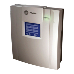
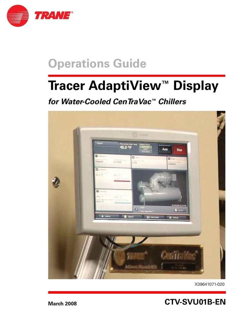
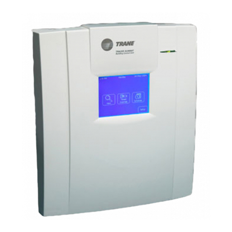
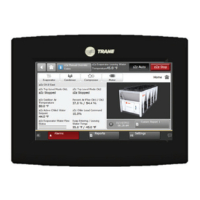
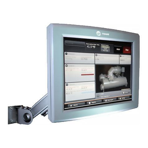
Trane Symbio 800 Control Upgrade Kit User manual

Symbio 800 Control Upgrade Kit
For Tracer CH530/CH531 DynaView™
Display
Installation Instructions
May 2022 CDUB-SVN001B-EN
CVRD Retrofit CH531 Control
CVHE, CVHF, CVHG Production CH530 Control
SAFETY WARNING
Only qualified personnel should install and service the equipment. The installation, starting up, and servicing of
heating, ventilating, and air-conditioning equipment can be hazardous and requires specific knowledge and training.
Improperly installed, adjusted or altered equipment by an unqualified person could result in death or serious injury.
When working on the equipment, observe all precautions in the literature and on the tags, stickers, and labels that are
attached to the equipment.
Distribution/use of this is limited to the Trane sales and service organization in support of Symbio 800 AdaptiView and is
not intended for independent third party use or for use apart from the Symbio 800 AdaptiView display upgrade for Tracer
CH530/CH531 DynaView display.

©2022 Trane CDUB-SVN001B-EN
Introduction
Read this manual thoroughly before operating or
servicing this unit.
Warnings, Cautions, and Notices
Safety advisories appear throughout this manual as
required.Yourpersonalsafetyandtheproperoperationof
this machine depend upon the strict observance of these
precautions.
The three types of advisories are defined as follows:
WARNING Indicates a potentially hazardous
situation which, if not avoided, could
result in death or serious injury.
CAUTIONsIndicates a potentially hazardous
situation which, if not avoided, could
result in minor or moderate injury. It
could also be used to alert against
unsafe practices.
NOTICE Indicatesasituationthatcouldresultin
equipment or property-damage only
accidents.
Important Environmental Concerns
Scientific research has shown that certain man-made
chemicals can affect the earth’s naturally occurring
stratospheric ozone layer when released to the
atmosphere. In particular, several of the identified
chemicals that may affect the ozone layer are refrigerants
that contain Chlorine, Fluorine and Carbon (CFCs) and
those containing Hydrogen, Chlorine, Fluorine and
Carbon (HCFCs). Not all refrigerants containing these
compounds have the same potential impact to the
environment. Trane advocates the responsible handling
of all refrigerants-including industry replacements for
CFCs and HCFCs such as saturated or unsaturated HFCs
and HCFCs.
Important Responsible Refrigerant
Practices
Trane believes that responsible refrigerant practices are
important to the environment, our customers, and the air
conditioning industry. All technicians who handle
refrigerants must be certified according to local rules. For
the USA, the Federal Clean Air Act (Section 608) sets forth
therequirementsforhandling,reclaiming,recoveringand
recycling of certain refrigerants and the equipment that is
usedin theseservice procedures. Inaddition, somestates
or municipalities may have additional requirements that
must also be adhered to for responsible management of
refrigerants. Know the applicable laws and follow them.
WARNING
Proper Field Wiring and Grounding
Required!
Failure to follow code could result in death or serious
injury. All field wiring MUST be performed by qualified
personnel. Improperly installed and grounded field
wiring poses FIRE and ELECTROCUTION hazards. To
avoid these hazards, you MUST follow requirements
for field wiring installation and grounding as described
in NEC and your local/state/national electrical codes.
WARNING
Personal Protective Equipment (PPE)
Required!
Failure to wear proper PPE for the job being undertaken
could result in death or serious injury. Technicians, in
order to protect themselves from potential electrical,
mechanical, and chemical hazards, MUST follow
precautions in this manual and on the tags, stickers,
and labels, as well as the instructions below:
• Before installing/servicing this unit, technicians
MUST put on all PPE required for the work being
undertaken (Examples; cut resistant gloves/sleeves,
butyl gloves, safety glasses, hard hat/bump cap, fall
protection, electrical PPE and arc flash clothing).
ALWAYS refer to appropriate Safety Data Sheets
(SDS) and OSHA guidelines for proper PPE.
• When working with or around hazardous chemicals,
ALWAYSrefertotheappropriateSDSandOSHA/GHS
(Global Harmonized System of Classification and
Labeling of Chemicals) guidelines for information on
allowable personal exposure levels, proper
respiratory protection and handling instructions.
• If there is a risk of energized electrical contact, arc, or
flash, technicians MUST put on all PPE in accordance
with OSHA, NFPA 70E, or other country-specific
requirements for arc flash protection, PRIOR to
servicing the unit. NEVER PERFORM ANY
SWITCHING, DISCONNECTING, OR VOLTAGE
TESTING WITHOUT PROPER ELECTRICAL PPE AND
ARC FLASH CLOTHING. ENSURE ELECTRICAL
METERS AND EQUIPMENT ARE PROPERLY RATED
FOR INTENDED VOLTAGE.

WARNING
Follow EHS Policies!
Failure to follow instructions below could result in
death or serious injury.
• All Trane personnel must follow the company’s
Environmental, Health and Safety (EHS) policies
when performing work such as hot work, electrical,
fall protection, lockout/tagout, refrigerant handling,
etc. Where local regulations are more stringent than
these policies, those regulations supersede these
policies.
• Non-Trane personnel should always follow local
regulations.
Introduction
CDUB-SVN001B-EN 3
Copyright
Thisdocumentandtheinformationinitarethepropertyof
Trane, and may not be used or reproduced in whole or in
part without written permission. Trane reserves the right
torevisethispublicationatanytime,andtomakechanges
to its content without obligation to notify any person of
such revision or change.
Trademarks
All trademarks referenced in this document are the
trademarks of their respective owners.
Other Required Manuals
Thismanualmustbe usedwiththefollowingpublications
(or their most recent versions):
• CVHE-SVX005*-EN1,Installation, Operation, and
Maintenance - CVHE, CVHF, and CVHG Water-Cooled
CenTraVac™ Chillers With Symbio Control
• CTV-SVU004*-EN1, Operations Guide - Tracer®
AdaptiView™Display for CenTraVac™Water-Cooled
Chillers with Symbio
• CTV-SVP004*-EN1, Tracer TU Service Tool for Water-
Cooled CenTraVac Chillers with Symbio Control
• CTV-SVD005*-EN1, Diagnostics Manual - Diagnostic
Descriptions, Troubleshooting Tables, and Control
Component Overview for Water-Cooled CenTraVac™
Chillers with Tracer AdaptiView™ Control
• BAS-SVU047*-EN1,GettingStartedGuide:TUService
Tool
• CVRF-SVP01*-EN, Programming Guide: Tracer
Symbio Panel Upgrade
Required Tools
Normal service tools arerequired to perform the majority
of the work. A service technician with a well stocked tool
chest should have the right tools to perform the job.
In addition to the normal service tools and hardware, the
following is a partial list of specific field supplied
hardware/softwarecomponentsandspecial toolsthat are
also required to perform the display retrofit:
• An RS-232 male DB9 to female DB9 pin to pin serial
cable to connect the DynaView to a PC or laptop
computer.
Note: The cable must not be a “null-modem” cable.
The cable must be less than 50 feet in length.
The RadioShack®part number for the proper cable is
26-117B.
• TypeAtoTypeBUSBcabletoconnecttheSymbio800
controller to a PC or laptop computer.
• A PC or laptop computer equipped with the following:
– TechView™ service software, version 12.1 or
newer.
– Tracer TU service software, version 2.02 or newer.
– Rover™servicesoftware(onlyrequiredifthechiller
is equipped with a LonTalk® Comm5 board).
• South pole magnet screwdriver (TOL01343).
• Electronics vacuum.
Field-Provided Material
Some field provided material will be required to perform
the display retrofit. A list of material is provided here to
help the technician to plan ahead and to avoid material
shortages at the job site.
• Wire,redandgreen#16 AWGcontrolwire-requiredto
make the connections between the power supply and
existing transformer.
• Wire connectors.
• Wire wrap or some other form of wire protection for
areas that wiring runs may come into contact with
sharp edges.
• Cable ties to help “clean up” wiring runs.
If the unit is located outside, a cover is required for the
display.
The Trane®part number for this cover is COV03916.
Revision History
Updated the Getting Started, Installation, Programming
chapters.
1A copy of this manual is shipped with the upgrade kit.

4CDUB-SVN001B-EN
Table of Contents
Other Required Manuals . . . . . . . . . . . . . . . . 3
Required Tools . . . . . . . . . . . . . . . . . . . . . . . . 3
Field-Provided Material . . . . . . . . . . . . . . . . . 3
General Information . . . . . . . . . . . . . . . . . . . . . 5
About This Manual . . . . . . . . . . . . . . . . . . . . 5
Unit Model Number . . . . . . . . . . . . . . . . . . . . 5
Model Number Descriptions . . . . . . . . . . . . . . 6
Getting Started . . . . . . . . . . . . . . . . . . . . . . . . . . 7
Nameplate . . . . . . . . . . . . . . . . . . . . . . . . . . . . 7
Symbio 800 AdaptiView Display Upgrade Kit
Contents . . . . . . . . . . . . . . . . . . . . . . . . . . . . . 7
Running the IPC Bus . . . . . . . . . . . . . . . . . 8
Installation . . . . . . . . . . . . . . . . . . . . . . . . . . . . . 10
ChecktheConfigurationandSet-Pointsinthe
DynaView Display . . . . . . . . . . . . . . . . . . 10
Save the DynaView Configuration and Set-
Points . . . . . . . . . . . . . . . . . . . . . . . . . . . . . 10
Remove the Existing Control Panel Door . 11
Install New Control Panel Door and Symbio
800 Controller . . . . . . . . . . . . . . . . . . . . . . . . 11
Choosing Display Arm Mounting Location 12
Alternative mounting location: . . . . . . . . 13
Mounting Display Arm . . . . . . . . . . . . . . . . 13
AdjustingtheTracerAdaptiViewDisplayArm
14
Install Power Supplies and Hardware . . . 15
Install 1A2 Power Supply—CH530 If Not Al-
ready Present . . . . . . . . . . . . . . . . . . . . . . 15
Install 1A2 Power Supply - CH531 Prebuilt
Panels . . . . . . . . . . . . . . . . . . . . . . . . . . . . 15
Install Quad Relay Output LLID—CH530 If Us-
ing Chiller Control Sequence 1 . . . . . . . . 16
Install Communication Cable Between 1A1
and 1A2 Power Supplies . . . . . . . . . . . . . 16
Connect Input Power Wiring to 1A2 Power
Supply . . . . . . . . . . . . . . . . . . . . . . . . . . . . 17
RoutingNew WireIntoand Outofthe Control
Panel Enclosure . . . . . . . . . . . . . . . . . . . . 17
Wiring Connections to the Display and Sym-
bio 800 Controller . . . . . . . . . . . . . . . . . . . 17
Solid State Oil Heater Relay Installation . 20
Mounting Location . . . . . . . . . . . . . . . . . . 20
Installation . . . . . . . . . . . . . . . . . . . . . . . . .21
Install Options . . . . . . . . . . . . . . . . . . . . . . . .22
LON Option Installation . . . . . . . . . . . . . . .22
Communication Option . . . . . . . . . . . . . . .22
Communication Device Mounting . . . . . .23
Water Flow Measurement Options . . . . . .24
Energy Meter Option Installation . . . . . . .25
Expansion Module Option . . . . . . . . . . . . .26
Before Restoring System Power . . . . . . . .27
Restoring System Power . . . . . . . . . . . . . .27
Programming . . . . . . . . . . . . . . . . . . . . . . . . . . .28
Programming the Symbio 800 AdaptiView 28
Start-Up . . . . . . . . . . . . . . . . . . . . . . . . . . . . . . . .31
Wiring Diagrams . . . . . . . . . . . . . . . . . . . . . . . .32

CDUB-SVN001B-EN 5
General Information
About This Manual
The step-by-step instructions outlined in this manual
describe the procedures required to successfully upgrade
anolderTracer™CH530DynaViewequippedCVHE,CVGF,
CVHF, CVHG, CDHF, or CDHG CenTraVac™ chiller to a
Symbio800 AdaptiViewdisplaysystem. This manualalso
provides instructions and describes the procedures
required to upgrade a CH531 prebuilt panel retrofit-
equipped chiller to a Symbio 800 AdaptiView display
system.
Notice that the installation instructions in this manual are
divided into the following general topic areas:
1. Check the configuration and set-points in the
DynaView display.
2. Save the DynaView display configuration and set-
points.
3. Shut down power.
4. Remove the old control panel door.
5. Install new control panel door and Symbio 800
controller.
6. Choosing display arm mounting location.
7. Mount display arm and new display.
8. Install 1A2 power supply (if not already present).
9. Install 1A2 power supply on CH531 prebuilt panels.
10. Install quad relay output LLID (required if using chiller
control sequence 1).
11. Installcommunicationcablebetweenthe 1A1and 1A2
power supplies.
12. Connect input powerwiring to the 1A2 power supply.
13. Routing new wire into and out of the control panel
enclosure.
14. Wiring connections to the Tracer AdaptiView display
and the Symbio 800 controller.
15. Before restoring system power.
16. Restoring system power.
17. Programming the Tracer AdaptiView display.
18. Full page schematic wiring diagrams.
Unit Model Number
For service purposes, Trane Model CDUB Symbio 800
AdaptiView display upgrade packages are assigned a
multiple character alphanumeric model number that
precisely identifies each unit.
An explanation of the identification code that appears on
the unit nameplate is shown below. Use of the service
model number will enable the owner/operator, installing
contractors, and service technicians to define the
operation, components and options for any specific unit.
Refertothemodelnumberprintedonthenameplatewhen
ordering replacement parts or requesting service.

6CDUB-SVN001B-EN
Model Number Descriptions
Digit 1, 2, 3 — Unit Function
CDU = Color, Display, Upgrade
Digit 4 — Development
Sequence
B = Symbio 800 Chiller Controller
Digit 5 — Control Upgrade1
1 = CH530 Simplex
2 = CH530 Duplex
3 = CH530 Gear Drive
4 = CH531
5 = UC800 CVRE
6 = UC800 CDUA
7 = UC800 CTV Simplex
8 = UC800 CTV Duplex
9 = UC800 ECTV
A = UC800 Agility
B = UC800 CVHS
C = UC800 CVHM
Digit 6 — Global Connector Kit
0 = No Global Connector Kit Option
A = With Global Connector Kit
Option
Digit 7 — Chiller/Tower Water
Flow Display
0 = No Chilled/Tower Water Flow
Display
1 = Dual Pressure Sensors
2 = Flow Meter Customer Provided
Digit 8 — Solid State Oil Relay
Control
0 = No Solid State Relay
A = Solid State Relay Only
B = Solid State Relay W/ELM01116
C = Solid State Relay W/ELM08119
Digit 9 — Tracer Interface
Control Module
0 = Without Communication Module
2 = With Generic BAS
5 = LonTalk Communication
Digit 10, 11— Design Sequence
AA = Symbio 800 Upgrade Release
Digit 12 — Heat Recovery/
Auxiliary Condenser
0=No
1=Yes
Digit 13 — Air-Fi Operation
0=No
1=Yes
Digit 14 — Wi-Fi Operation
0=No
1=Yes
Digit 15 — LTE Operation
0=No
1=Yes
Digit 16 — NEMA 4
Communication Box
0 = Without Box
1 = Small Box
2 = Large Box
Digit 17 — Energy Meter
Operation
0=No
A = Energy Meter, 480V and Low
B = Energy Meter, 575V and 600V
C = Energy Meter, Medium Voltage,
100A CT
D = Energy Meter, Medium Voltage,
100A CT
E = Energy Meter, Medium Voltage,
400A CT
Digit 18 — Head Pressure
Control
0=No
1=Yes
Digit 19 — Expansion Module
0=No
1 = Expansion Module XM30
2 = Expansion Module XM32
3 = Expansion Module XM70
4 = Expansion Module XM30+XM32
1Digit 5 does not affect the kit contents. It is strictly for record keeping.

CDUB-SVN001B-EN 7
Getting Started
To properly install an Symbio™ 800 AdaptiView display
upgrade kit, the technician must have good knowledge of
the Symbio 800 control systems. Training in Symbio 800
controls is highly recommended before beginning this
upgrade.
Nameplate
ASymbio™800AdaptiViewdisplayupgradenameplateis
included in the kit to be installed near the original
nameplateonthecontrolpanel.Alwaysprovidethemodel
number and serial number information from the
nameplate when making inquiries, ordering parts, or
literature for the Symbio 800 AdaptiView display system.
Symbio 800 AdaptiView Display
Upgrade Kit Contents
Figure 1. Symbio™ 800 AdaptiView display upgrade
nameplate example
SYMBIO 800 UPGRADE CONTROL FOR USE ON
LIQUID CHILLERS
MODEL NO: CDUB3A105AA00100000
SERIAL NO: L22C01079
ORDER NO: LARRYSP4
ORIGINAL SERIAL NO: L22A00000
LITERATURE:
CDUB-SVN01*-EN
CTV-SVU004*-EN
CVRF-SVP001*-EN
CTV-SVD005*-EN
CVHE-SVX005*-EN
BAS-SVU047*-EN
CTV-SVP004*-EN
www.trane.com/Patent
Table 1. Basic bill of material for Symbio™ 800 control upgrade kit
Description Qty. Part Number(a) Mnemonic Part Number(a)
Display arm 1X45091462010 ARM00848
Symbio AdaptiView color display 1X13760359001 MOD03183
Symbio 800 controller 1X13651678020 MOD02979
Harness; Modbus distribution 1453730970001 WIR10397
Four plug Phoenix type terminal connector 2X19220085030 CON00431
DIN Rail end stop 2X13492732001
Ethernet cable for Symbio 800 to display connection,
3700 mm in length (See, Figure 2, p. 8)1X19070632020 CAB01206
Male to Female wire harness extension, 1 meter in
length (See, Figure 3, p. 8)1X19051623010 CAB01149
Wire harness extension, Female connector to stripped
end, 1 meter in length (Refer to Figure 3, p. 8)1X19051625020 CAB01155
2-conductor power supply communication cable, 8
inches in length (See, Figure 4, p. 8)1X19051243010 CAB00974
USB Type B service port cable (See, Figure 5, p. 8) 1 X19140818010 CAB01260
USB Type B service port cap 1X19201118010 CAP01053
Bushing, 0.88 inch diameter 2X19100013000 BUS00866
Power supply (for installation as 1A2 power supply) 1X13650737060 BRD02102
Power supply mounting bracket 1X19090702010 BRK03306
10-32 x 0.50-inch screw 4X25330033410 SCR00889
5/16-18 x 1 inch hex head cap screw 4X25012400000 SCR01839
5/16-inch lockwasher 4X22020400000
5/16-inch hex nut 4X28020700000
Serialized nameplate decal 1X39001817010
Nameplate protector 1X39001166030
10-32 x 1.00-inch screw 1X25330033450 SCR01014
Quad relay output 1X13650806050 BRD04879
Bracket; CH531 sub panel 1507104470100 BRK05365

Getting Started
8CDUB-SVN001B-EN
Notes:
•Bk Black wire
•R Red wire
Figure 5. USB Type B service port cable
Running the IPC Bus
There are several ways to string the IPC communication
bus on the chiller. The Symbio™ 800 AdaptiView display
upgrade kit includes a general wire kit that has several
differenttypes ofwires.Anexampleofawiringlayoutcan
be seen in the below figure. Each application will vary
depending on the options. You may have extra cables, or
may be short needed cables. Extra cables can be ordered
through your local Trane Parts Center. Use the latest
version of PART-SVB16*-EN (Tracer CH530/CH531
Pluggable Connector System) for identification of
individual cables.
WARNING
Hazardous Voltage w/Capacitors!
Failure to disconnect power and discharge capacitors
before servicing could result in death or serious injury.
Disconnect all electric power, including remote
disconnects and discharge all motor start/run
capacitors before servicing. Follow proper lockout/
tagout procedures to ensure the power cannot be
inadvertently energized. For variable frequency drives
or other energy storing components provided by Trane
or others, refer to the appropriate manufacturer’s
literature for allowable waiting periods for discharge of
capacitors. Verify with a CAT III or IV voltmeter rated
per NFPA 70E that all capacitors have discharged.
WARNING
PPE for Electric Contact and Arc/Flash
Required!
Failure to disconnect power and discharge capacitors
before servicing could result in death or serious injury.
Disconnect all electric power, including remote
disconnects and discharge all motor start/run
capacitors before servicing. Follow proper lockout/
tagout procedures to ensure the power cannot be
inadvertently energized. For variable frequency drives
or other energy storing components provided by Trane
or others, refer to the appropriate manufacturer’s
literature for allowable waiting periods for discharge of
capacitors. Verify with a CAT III or IV voltmeter rated
per NFPA 70E that all capacitors have discharged.
Bracket; AdaptiView display Mt. 1X05010050010 BRK04345
Hex HD screw; 7/16-20*1 342250080710
Lockwasher, Helical spring; 7/16 3X22020026060
Normar size flatwasher; 7/16 3X22050232150
Nut Hex; 7/16-20 3X28020003110
Door assembly 1506898140100
Figure 2. Ethernet cable for Symbio 800 controller to
display connection
Figure 3. Wire harness extensions: M to F connectors
and F connector to stripped
Figure 4. Two-conductor power supply
communication cable
(a) All part number information in this table is subject to change at any time.
Table 1. Basic bill of material for Symbio™ 800 control upgrade kit (continued)
Description Qty. Part Number(a) Mnemonic Part Number(a)

Figure 6. Sample of IPC cable routing
Control Panel
CAB01155
leads to female
CAB01149
short, male to female
CAB01146
short, male to 2 female
Transducer LLID
Getting Started
CDUB-SVN001B-EN 9
To connect the IPC bus to the control panel LLIDs, thread
thebusintothecontrolpanelviaaknockoutorotherentry.
The CAB01155 connector has a female plug on one end
and four stripped leads on the other end. Attach the four
stripped leads to the power supply in the control panel.
Figure 7. Connecting the stripped leads to the power
supply
Notes:
•R - Red wire for 24 Volts direct current
•Bk - Black wire for ground
•Bl - Blue wire for IPC+ connection
•Gr - Gray wire for IPC- connection
Makesure all devicesandLLIDs areconnectedtogether in
some way. Use the correct cables so that you don’t have
any open plugs when finished. Avoid placing wire ties
directly over plug connectors. This may press on the lock
mechanism and over time the plugs may release.
Table 2. Cables shipped for various options
CAB01146
branch M(a)
to 2 F
500 mm
CAB01147
branch M to
2F
1000 mm
CAB01148
branch M to
3F
500 mm
CAB01149
extension M
to F
1000 mm
CAB01150
extension M
to F
2000 mm
CAB01152
extension M
to leads
1000 mm
CAB01154
extension M
to receptacle
1 M
CAB01155
extension F to
leads
1000 mm
Standardpanelcables555109122
Actuator-stepper 1
Oil protection—full, low
pressure or high pressure 1 1
Heat recovery/aux
condenser 1 1 1
Hot gas bypass—electric
actuator 1 1
Hot gas bypass—pulse
actuator 1 1
Cold water reset 1 8
Enhanced protection 1 2 1 3
(a) The letters M and F represent male and female connectors.

10 CDUB-SVN001B-EN
Installation
Check the Configuration and Set-Points in
the DynaView Display
Important: Verify CH530 firmware is upgraded to the
most recent version before creating the
chiller service report for conversion to
Symbio.
The conversion utility is only designed to
workwiththemostrecent version ofCH530
firmware.
1. Check the current configuration of the DynaView and
confirm that all settings are correct. Make any
necessary changes.
2. Check all of the current chiller set-points programmed
intotheDynaViewandconfirmthattheyareallcorrect
for the unit. Make any necessary changes.
Save the DynaView Configuration and
Set-Points
Using KestrelView™ on a PC or laptop computer:
1. Generate a Chiller Service report from the DynaView
with Level 4 active.
2. Be sure tocheck all of the boxes to ensure thatyou get
a complete report.
Shut Down Power
1. Using Lock out Tag out safety procedures, shut down
the chiller’s main power.
2. Openallstarterandcontrolpaneldisconnectswitches
and secure them in the open position.
3. Confirmthatthepowerisofftothecontrolpanelofthe
chiller.
Figure 8. KestrelView screenshot—accessing chiller service report
WARNING
Hazardous Voltage w/Capacitors!
Failure to disconnect power and discharge capacitors
before servicing could result in death or serious injury.
Disconnect all electric power, including remote
disconnects and discharge all motor start/run
capacitors before servicing. Follow proper lockout/
tagout procedures to ensure the power cannot be
inadvertently energized. For variable frequency drives
or other energy storing components provided by Trane
or others, refer to the appropriate manufacturer’s
literature for allowable waiting periods for discharge of
capacitors. Verify with a CAT III or IV voltmeter rated
per NFPA 70E that all capacitors have discharged.

Installation
CDUB-SVN001B-EN 11
Remove the Existing Control
Panel Door
1. Unplug the wire feeding the DynaView on the existing
controlpaneldoor.Thismayrequirecuttingsomewire
ties.
2. Disconnect the equipment ground wire from the door.
3. While supporting the door to prevent it from twisting
or falling, remove the two hinge pins using a small
punch and a set of pliers.
4. Set the door aside.
Install New Control Panel Door
and Symbio 800 Controller
1. Set the new control paneldoor in place and install the
hinge pins.
2. Connect the equipment ground wire to the weld-stud
on the door using the 10-32 hex lock nut with star
washer provided.
3. Clip the Symbio 800 controller onto the DIN rail
secured to the back side of the door.
Important: Note the correct orientation of the
Symbio 800 controller as shown in the
following figure.
a. InstallDINrailendstopsoneachsideoftheSymbio
800 controller.
b. Tighten the center screw on each stop to lock it in
position to prevent the Symbio 800 controller from
moving.
Figure 9. Existing door removal, steps 1 and 2
Figure 10. Existing door removal, step 3
Figure 11. Mounting new control panel door
Figure 12. Equipment ground wire connected to new
door

Installation
12 CDUB-SVN001B-EN
4. Install the round end of the USB Type B service port
cableintothecut-outonthedoorandsecureitwiththe
plastic nut.
a. Remove the rubber protective plug from the inside
of the weld nut.
b. Secure the dust cover to the outside of the door by
inserting the #4-40 x 0.25-inch machine screw
provided through the shackle on the end of the cap
chain, and then threading the screw into the weld
nut.
c. Plug the opposite end of the USB cable into the
appropriate port in the Symbio 800 controller.
Choosing Display Arm Mounting
Location
Recommended mounting location:
Thedisplayarmassemblyisdesignedtobesecuredtothe
side of the control panel or to one of the two mounting
brackets underneath the control panel enclosure.
Note: We also provide a production display arm bracket
BRK04345 provided that where applicable can be
mounted to the existing right hand side control
panel mounting arm.When used, the holes on the
unused side should be plugged. It is preferable to
securethearmtotheright-handmountingbracket,
which is at the opposite end of the control panel
enclosure from the door hinges.
Figure 13. Mounting Symbio 800 controller onto new control panel door
Figure 14. Installation of the USB service port cable
Figure 15. Production arm bracket

Installation
CDUB-SVN001B-EN 13
Alternative mounting location:
If the control panel mounting brackets are obstructed by
thicklayersofinsulation,electricalconduits,etc.,suchthat
itisnot possibletoeffectivelyinstallthedisplayarminthe
recommended mounting location, it is permissible to
mount the display arm onto the side of the control panel
enclosure as shown in the below figures.
It is preferable to secure the arm to the right-hand end of
the control panel enclosure, which is at the opposite end
of the cabinet from the door hinges. However, if a specific
retrofit situation makes it necessary to mount the display
armontheleft-handendoftheenclosure,pleasenotethat
allofthecablesprovidedwithinthedisplayupgradekitare
long enough to allow this installation location to be
utilized.
If an alternative mounting location is chosen, please be
suretotake all ofthe precautionsnecessary toensurethat
no electrical components inside the control panel
Mounting Display Arm
Note:
•If utilizing the alternative mounting location, before
drilling the display arm mounting holes through the
sideof the controlenclosure,the following stepsmust
be taken to prevent damaging any of the electrical
components inside of the enclosure:
– Carefully position the template to ensure thatall 4
mounting holes will be located such that the
installed mounting bolts will not come intocontact
with any of the electrical components.
– Before drilling, ensure that all electrical
components are adequately protected from metal
filings. Temporarily remove components if
necessary. Failure to prevent metal filings from
lodging against or inside of these electrical
components can cause them to fail when they are
re-energized.
– Before and during drilling, ensure that all electrical
cables and wires are not in line with the path of the
drill bit. Failure to prevent damage to these
components can cause electrical shorts and/or
sparks to occur when the system is re-energized.
– After all 4 mounting holes are drilled, use an
electronics vacuum to remove any dirt, debris, or
metal filings that may have accumulated inside of
the control enclosure.Be sure to properly reinstall
anycomponentsthatweretemporarilyremovedfor
their protection during the drilling process.
1. Using the template provided, mark the location of the
4 mounting holes required on the chosen mounting
bracket.
2. Use a 3/8-inch bit to drill the holes.
Figure 16. Recommended mounting location on right-
hand control panel bracket
Figure 17. Alternative mounting location chosen due to
retrofitted insulation layers
Figure 18. Arm/display assembly mounted at
alternative location

Installation
14 CDUB-SVN001B-EN
.
3. Secure the arm to the control panel bracket using the
5/16-18x1-inchhexbolts,5/16-inchlockwashers,and
5/16 - 18 hex nuts provided. Note that included
production arm bracket can also be bolted to panel
mounting bracket.
4. Securely fasten the Tracer AdaptiView display to the
mounting plate on the end of the display arm with the
hardware provided.
5. After the display is attached, recheck the arm tension.
Thearmtensionshouldbe setsothatthe display does
not spring up or sag down out of the position it is
moved to by the operator.
Adjusting the Tracer AdaptiView Display
Arm
The Tracer AdaptiView display arm may be too loose or
too tight and in need of adjustment. To adjust the tension
on the display arm:
1. Therearethreejoints onthedisplayarm that allowthe
TracerAdaptiViewdisplaytobepositionedatavariety
of heights and angles (refer to items labeled 1, 2, and
3 in the below figure). At each joint in the display arm
thereiseitherahexbolt(1and2)orhexscrew(3).Turn
thehexboltorscrewintheproperdirectiontoincrease
or decrease tension.
Note: Each hex bolt or screw is labeled with ‘loosen’/
‘tighten’, or '+'/'–' indicators.
2. Joint3hasa6mmhexscrewcontrollingthetensionon
a gas spring, which allows the Tracer AdaptiView
display to tilt up and down.
3. Joints1and2arecoveredbyaplasticcap.Removethe
plasticcaptoaccessthehexbolt.Adjustusinga13 mm
wrench as necessary.
4. To adjust the swivel of the Tracer AdaptiView display
(the spin right and left similar to the steering wheel on
acar),youneedtoadjustthehexboltlocatedinsidethe
display arm back plate. This adjustment needs to be
doneBEFOREattachingthedisplay.Usea9/16-inch or
14 mm wrench.
5. Use a 13 mm wrench to adjust thebolt (item labeled 4
in the above figure) that allows the entire display arm
to swivel to the left and right.
Figure 19. Display arm mounting holes drilled through
right-hand panel bracket
Figure 20. Production arm bracket
Figure 21. Attaching Tracer AdaptiView display to arm
CAUTION
Tension in Display Support Arm!
Failure to follow instructions below could result in
unexpected movement of the spring-loaded support
arm which could result in minor to moderate injury.
Ensure that the support arm is in the full upright
position when removing the Tracer AdaptiView display
from the support arm.
Figure 22. Joint locations on the display arm
1
2
3
4

Installation
CDUB-SVN001B-EN 15
Install Power Supplies and
Hardware
Install 1A2 Power Supply—CH530 If Not
Already Present
Note: Proceeddirectlytothenextstageoftheinstallation
process:
•for CH531 applications, or
•Iftherearealreadytwopowersupplies(1A1and
1A2) in place from the previous CH530 control
system.
1. Find the factory-drilled mounting holes on the inner
back wall of the control panel enclosure tothe right of
the existing power supply.
2. Attach the power supply to the mounting bracket with
the hardware provided.
3. Attach the power supply assembly to the back wall of
the enclosure using the 10-32 x 0.50-inch screws
provided.
Note: In all subsequent manual pages, this new power
supplywillbe referred toas the1A2 power supply,
while the preexisting power supply from the
original control system will be referred to as the
1A1 power supply.
Install 1A2 Power Supply - CH531 Prebuilt
Panels
1. Locate and remove the vent line solenoid time delay
relay and base.
Note: Do not unwire the base. The wires should be
long enough to reach the new location. Use
caution when removing the timer because the
center alignment post is very fragile.
2. Locate and remove the 1A1 power supply LLID and
bracket.
Note: Do not unwire the 1A1 power supply LLID. The
wires should be long enough to reach the new
location.
3. Locate and remove the middle back panel securing
screw on the right side.
4. Install the new sub back panel provided with the kit.
a. Secure the left side of the bracket using two #10-32
by 1/2-inch screws and the holes emptied by the
removal of the power supply bracket.
b. Securethe rightsideof thebracket using one 10-32
x 1.00-inch screw and the hole emptied by the
removal of the back panel securing screw.
5. Using the screws that were removed in Step 2, attach
the existing power supply LLID onto the new panel in
the holes labeled 1A1.
6. Using the screws that were removed in Step 1, attach
the vent line solenoid time delay relay and base in the
holes labeled 1K20.
Important: Thetimermustbealignedcorrectlywiththe
base.
7. With the hardware provided, attach the new power
supply to the mounting bracket.
8. Using 10-32 x 0.50-inch screws provided, attach the
power supply assembly to the new panel in the holes
labeled 1A2.
Note: In all subsequent manual pages, this new power
supplywill bereferredto as the1A2powersupply,
while the preexisting power supply from the
original control system will be referred to as the
1A1 power supply.
Figure 23. Installation of second power supply

Installation
16 CDUB-SVN001B-EN
Install Quad Relay Output LLID—CH530 If
Using Chiller Control Sequence 1
Notes:
•If the DynaView had CTV software and was using
control sequence 1, then installing the quad relay
outputLLIDisrequired.Todeterminethis,examinethe
chiller service report that was saved earlier. In the
configuration section, look for "Connected to" and in
the CH530 section, look for "Control Sequence". If
these items are “CTV” and “1”, respectively, then
adding the quad relay output LLID is required. If not,
then skip this procedure.
•If the quad relay output LLID is added, it also needs to
be bound in the programmingphase of the Symbio™
800.
1. RemoveLLIDs1A3dualrelay,1A5dualrelay,and1A10
dual relay output from the control panel. Refer to
Figure 67, p. 33.
2. Install the quad relay output LLID in an open space in
thecontrolpanel,ascloseaspossibletowherethe1A3
LLID was formerly located.
Note: Thismayalsorequiremovingsomeoftheother
LLIDs to different control panel locations.
3. Connect the wires from the previously removed LLIDs
to the quad relay output LLID terminals as shown in
Figure 67, p. 33.
Install Communication Cable Between
1A1 and 1A2 Power Supplies
Note: Proceed directly to the installation section
“Routing New Wire Into and Out of the Control
Panel Enclosure,” p. 17, if the 1A2 power supply
was already in place as part of the previous CH530
control system.
1. Connect the power supplies together at the J1
terminals using the 2-conductor power supply
communication cable provided.
Note: If the J1 terminals are already being used, the
communicationcablecaninsteadbeconnected
to the J11 terminals on both power supplies.
Notes:
•Bk - Black wire
•R - Red wire
Figure 24. Installation of 1A2 power supply
Figure 25. Communication cable install between 1A1 and 1A2 power supplies

Installation
CDUB-SVN001B-EN 17
Connect Input Power Wiring to 1A2 Power
Supply
Notes:
•Proceed directly to the next stage of the installation
process if the 1A2 power supply was already in place
as part of the previous CH530 control system.
•The full schematic wiring diagram can be found in
Figure 69, p. 35 of this manual.
1. Attach a Red 16 AWG wire between J2-1 on the 1A2
power supply and 1T1-X2.
2. Attach a Red 16 AWG wire between J2-2 on the 1A2
power supply and 1T1-X1.
3. Attach a Green 16 AWG wire between J2-3 on the 1A2
power supply and any available ground terminal on
the 1X1 terminal block.
Notes:
•Gn Green wire
•R Red wire
Routing New Wire Into and Out of the
Control Panel Enclosure
• Make use of the spare factory knock-outs that are
available on the right-hand end of the control
enclosure,forroutingallrequiredwiringrunsfromthe
Symbio800controllerandthe1A2powersupplyoutto
the connection points on the display.
• Plastic grommets are providedin the upgrade kit to
line the edges of the knock-outs used.
Note: Ifa specificretrofitsituation hasmade itnecessary
to mount the display arm on the left-hand panel
bracket or the left-hand end of the enclosure,
please note that all of the cables provided within
the display upgrade kit are long enough to allow
utilizing the spare factory knock-outs that already
exist on the back of the control panel enclosure.
Wiring Connections to the Display and
Symbio 800 Controller
Note: Also refer to the full schematic wiring diagram
located in Figure 69, p. 35 of this manual.
1. Ethernet communication cable installation:
a. Attach the head of the Ethernet cable to the display.
b. Route the cable through the wire channel on the
display arm.
Important: Leaveenoughslackinthecabletoallowthe
display arm to be moved through its full
range of motion without placing a strain on
the cable or the terminal connections.
c. Take the cable around the back side of the control
enclosure and feed it into the cabinet through one
of the spare factory provided cable knock-outs.
d. Insert the cable end into the Ethernet port on the
Symbio 800 controller.
WARNING
Ground Wire!
All field-installedwiring must be completed by qualified
personnel. All field-installed wiring must comply with
NEC and applicable local codes. Failure to follow this
instruction could result in death or serious injuries.
Figure 26. Input power wiring to the 1A2 power supply
Figure 27. Example of pre-existing spare factory knock-
outs on control enclosure

Installation
18 CDUB-SVN001B-EN
2. Install the Female connector to stripped end wire
harness extension to the 1A2 power supply (the first
half of the power supply run to the display):
a. Routethestrippedendofthiswireharnessthrough
the same cabinet knock-out used for the Ethernet
cable if possible, otherwise use one of the other
spare factory made knock-outs provided.
b. Connect each of the four individual wires to the
correct terminal of the removable J4 terminal plug
on the 1A2 power supply.
Figure 28. Ethernet cable installation between the display and Symbio 800 controller

Installation
CDUB-SVN001B-EN 19
Notes:
•R. Red wire for 24 Volts direct current
•Bk. Black wire for ground
•Bl. Blue wire for IPC+ connection (notactually used by
Tracer AdaptiView but connect anyway)
•Gr. Graywire forIPC- connection(not actually usedby
Tracer AdaptiView but connect anyway)
3. Complete the power supply connection to the display
using the Male to Female wire harness extension:
a. Connect the Male end of this cable to the Female
connector on the cable installed in Step 2.
b. Route the cable harness through the wire channel
on the display arm and connect the Female end to
the Male receptacle on the display unit.
Important: Leaveenough slackinthe cabletoallow for
thedisplayarmtobemovedthroughitsfull
range of motion without placing a strain on
the cable or the terminal connections.
Figure 29. Female to bare end wire harness install from outside cabinet in to 1A2
Figure 30. Completion of power supply connection to
the display

Installation
20 CDUB-SVN001B-EN
4. Connect the Symbio 800 controller to the 1A2 power
supplyusingthelengthof4-conductorcableprovided:
a. Connect each of the 4 individual wires on one end
ofthecabletothecorrectterminaloftheremovable
J5 terminal plug on the 1A2 power supply.
b. Route the other end of the cable inside of the
cabinet over to the Symbio 800 controller and
connecteachofthe4 individualwirestothecorrect
terminals on the controller.
Notes:
•R. Red wire for 24 Volts direct current
•Bk. Black wire for ground
•Bl. Blue wire for IPC+ connection
•Gr. Gray wire for IPC-connection
5. Secureallcablesinthewirechannelonthedisplayarm
with cable ties:
There are 2 factory-drilled holes provided in the wire
channel to aid in neatly securing the cables with cable
ties as is recommended.
Important: Wireprotection may be required at both
ends of the wire channel and at the door
hinge opening on the control panel
enclosure due to the potential presence of
sharp edges that could abrade or cut the
wires.
6. Usecabletiestocleanupandsecurewiringrunsinside
of the control panel enclosure.
Solid State Oil Heater Relay
Installation
Note: This procedure does not apply to new chillers
operating with R514A refrigerant. Chillers with
R514A refrigerant have solid-state relay for heater
control installed and configured by the factory.
Relay RLY02909 is provided for upgrading chillers with R-
123 refrigerant. This relay will operate with a 120V 15mA
signal, yet it will safely and quickly switch 120V loads up
to 25 amps. The oil heater’s amp draw is 6.25 amps at
120V, which is well within the capacity of RLY02909.
Mounting Location
The RLY02909 must be mounted directly onto a flat steel
face of the control panel, either on a side wall of the
enclosure, or on the back-plane panel. The mounting
surfaceactsasaheatsinkfortherelay,sothe relay should
be securely bolted to the mounting surface.
Note: Instructions included with the relay may require
removal of paint from the mounting surface, and
the use of a heat conductive paste between the
relayandthemountingsurface.Trane’slabtesting
indicatesthattheseadditionalstepsarenotneeded
for the low 6 or 7 amp draw that our heater will
apply to the relay. Securely mounting the relay to
any steel surface in the control panel is adequate
for our application.
Figure 31. Wire connections from 1A2 power supply J5
to Symbio 800 controller
Figure 32. Neatly secure and protect cables in display
arm wire channel
Table of contents
Other Trane Monitor manuals

Trane
Trane Tracer MP580 Reference guide

Trane
Trane Tracer AdaptiView User manual

Trane
Trane Tracer AdaptiView User manual

Trane
Trane Tracer TD7 Installation and operating instructions

Trane
Trane BCU Operator Display Instruction Manual

Trane
Trane Tracer Summit User manual

Trane
Trane TruSense RMWH Installation and operating instructions

Trane
Trane CVHE Quick setup guide

Trane
Trane Tracer TD-5 Installation and operating instructions

Trane
Trane AdaptiView User manual