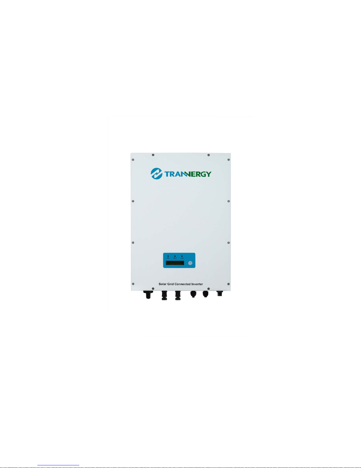
Trannergy PVI1300TL User manual
User Manual
PVI1300/1800/2300/2700/3000/3200/4000/4600/5400TL

User Manual 1
Contents
Copyright Declaration............................................................................................................... 3
1. Introduction........................................................................................................................... 4
1.1. Introduction.................................................................................................................... 4
1.2. How to Use this manual ................................................................................................. 4
1.3. Applied Designations (Warning, Caution, Note) ........................................................... 4
1.4. Important Safety Information......................................................................................... 5
1.5. General Safety Rules for Working on Electrical Equipment.......................................... 6
1.6. System Sizing................................................................................................................. 7
1.7. DC-switch....................................................................................................................... 7
2. Technical Description of Inverters........................................................................................ 8
2.1. Mechanical design.......................................................................................................... 8
2.2. Electrical system design................................................................................................. 9
3. Operation Mode Definition ................................................................................................. 11
3.1. Waiting mode ............................................................................................................... 11
3.2. Connecting mode.......................................................................................................... 11
3.3. Normal mode................................................................................................................ 11
3.4. Fault mode.................................................................................................................... 11
4. Installation and startup ........................................................................................................ 13
4.1. Installation precaution.................................................................................................. 13
4.2. Installing the inverter.................................................................................................... 16
4.3. Electrical connection.................................................................................................... 18
4.3.1 Connection to the grid (AC) for Product A............................................................ 19
4.3.2 Connection to the grid (AC) for Product B ............................................................ 22
4.3.3 Connection to the PV generator (DC) for Product A&B........................................ 22
4.4. Run the inverter............................................................................................................ 25
5. Human Machine Interface................................................................................................... 26
5.1. Control Panel................................................................................................................ 26
5.2. LCD Functions ............................................................................................................. 27
5.3. Language Settings ........................................................................................................ 27

2User Manual
5.4. Auto Test Settings ........................................................................................................ 28
5.5. Power Factor Settings................................................................................................... 30
5.6. Power Limit Settings.................................................................................................... 30
6. Communication and Monitoring......................................................................................... 31
6.1. Communication Interfaces............................................................................................ 31
6.2. Communication ............................................................................................................ 31
6.2.1. RS-232 Communication for single inverter type................................................... 31
6.2.2. RS-485 Communication for Several inverters....................................................... 32
6.2.3. Wireless................................................................................................................. 33
6.3. Monitoring.................................................................................................................... 33
7. Service and repair................................................................................................................ 34
7.1. Safety during service and repair................................................................................... 34
7.2. Troubleshooting............................................................................................................ 34
8. Technique specification....................................................................................................... 36
8.1. Electrical Specification................................................................................................. 36
8.1.1. Input Specification................................................................................................. 36
8.1.2. Output Specification.............................................................................................. 37
8.1.3. General Data.......................................................................................................... 37
9. Qualification........................................................................................................................ 39
10. Contact Information........................................................................................................... 40
Appendix A: FAQ (Frequently asked questions).................................................................... 41
Appendix B: Abbreviation ...................................................................................................... 42

User Manual 3
Copyright Declaration
The copyright of this manual belongs to Trannergy Co., Ltd. Any corporation or
individual should not plagiarize, partially copy or fully copy it (including software,
etc.), and no reproduction or distribution of it in any form or by any means. All rights
reserved. Trannergy reserves the right of final interpretation. This manual is subject to
change according to user’s or customer’s feedback. Please check latest version at:
http://www.trannergy.com.
4User Manual
1. Introduction
1.1. Introduction
This manual describes Trannergy solar inverters PVI1300TL,PVI1800TL ,PVI2300TL,
PVI2700TL,PVI3000TL,PVI3200TL, PVI4000TL, PVI4600TL and PVI5400TL. These
products are among the most technologically advanced and efficient inverters on
the market and are designed to ensure a stable power supply for many years.
The PVI inverter is a transformerless based inverter.
1.2. How to Use this manual
Please read the safety instructions in this manual first. Throughout the manual it
is assumed that the reader is familiar with AC and DC installations and knows the
rules and regulations for electrical equipment and for connecting it to the utility
AC grid. It is especially important to be familiar with the general safety rules for
working with electrical equipment.
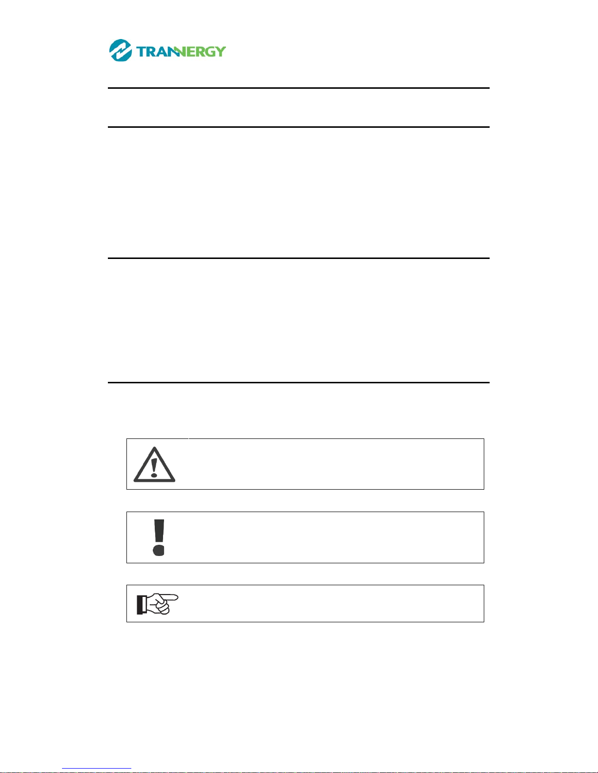
1.3. Applied Designations (Warning, Caution, Note)
Throughout the manual important information is shown at different levels
depending on the character of the information, as shown here:
Safety information important for human safety. Violation of
warnings may result in injury to persons or death.
Information important for the protection of property. Violation
of this type of information may cause damage and
loss of
property.
Useful additional information or “Tips and Tricks" on specific
subjects.
This manual suits for next models
8
Table of contents
Other Trannergy Inverter manuals


Popular Inverter manuals by other brands


BARRON
BARRON EXITRONIX Tucson Micro Series installation instructions

Baumer
Baumer HUBNER TDP 0,2 Series Mounting and operating instructions

electroil
electroil ITTPD11W-RS-BC Operation and Maintenance Handbook

Silicon Solar
Silicon Solar TPS555-1230 instruction manual

Mission Critical
Mission Critical Xantrex Freedom SW-RVC owner's guide

HP
HP 3312A Operating and service manual


