TransCore Encompass 1150 User manual

Trusted Transportation Solutions
16-1150-004 Rev E 7/2020
Encompass® 1150
Mobile Reader
TransCore’s Encompass 1150 (E1150) Mobile RFID Reader oers a portable and cost
eective solution for decoding or verifying RFID tags. The lightweight, ergonomic
design makes it the ideal choice for parking, tolling, railroad, ground management,
transportation asset management, field service, and warehouse operations.
This document describes the procedures to set up and use an Encompass 1150 (E1150) Mobile Reader.
Caution: Do not open the E1150 case. Opening the case will damage and disable the unit and
void the warranty.
Required Supplies
You need the following additional materials and/or tools to complete the reader installation:
• Host PC using Windows 2000 or newer operating system with at least one USB port
• USB communications cable provided with E1150
• USB wall charger provided with E1150
• USB drive with Field Configuration Software (FCSW)
• Test tag provided with E1150

User Guide
Page 2
Installing the Software
Install the Field Configuration Software (FCSW)
Insert the FCSW USB drive into the host computer and load the software. The program installs a shortcut
icon for the software and a shortcut icon for the E1150 mobile reader instructions to the desktop.
CAUTION: Do not launch the field configuration software program at this time.
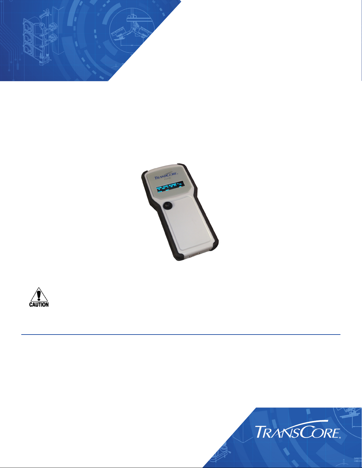
E1150 Setup
Note: The E1150 mobile reader is designed to be used in any environment, accommodating a wide
temperature range as well as meeting an IP64 rating.
1. Place the E1150 on a flat surface.
2. Plug the USB cable into the power adapter and into the USB port at the base of the E1150. Plug
the power adapter into a standard 110V AC wall outlet. Allow the E1150 to fully charge. The green
battery indicator located on the E1150 screen will be completely illuminated when the unit is ready
for use. After initial setup, the E1150 can be charged via the power adapter or any USB port.
Note: The automatic charger shuto allows for the E1150 to remain connected to the charger after
completion of a charge cycle. The charging notification and state of charge indication will remain
on the display while the unit is connected to a charging USB port.
3. Once charged, connect the USB cable from the USB port at the base of the E1150 to one of the
host computer’s USB ports. Allow the device driver to be detected and installed automatically. If
the device driver fails to automatically load, disconnect the E1150 from the host computer. Locate
the device driver setup executable file at http://www.ftdichip.com/Drivers/D2XX.htm and download
the driver from the FTDIchip website, or install the driver from the FCSW USB drive. Choose the
setup executable file for the appropriate operating system, then launch the downloaded software.
Reconnect the E1150 and allow it to be detected by the operating system.
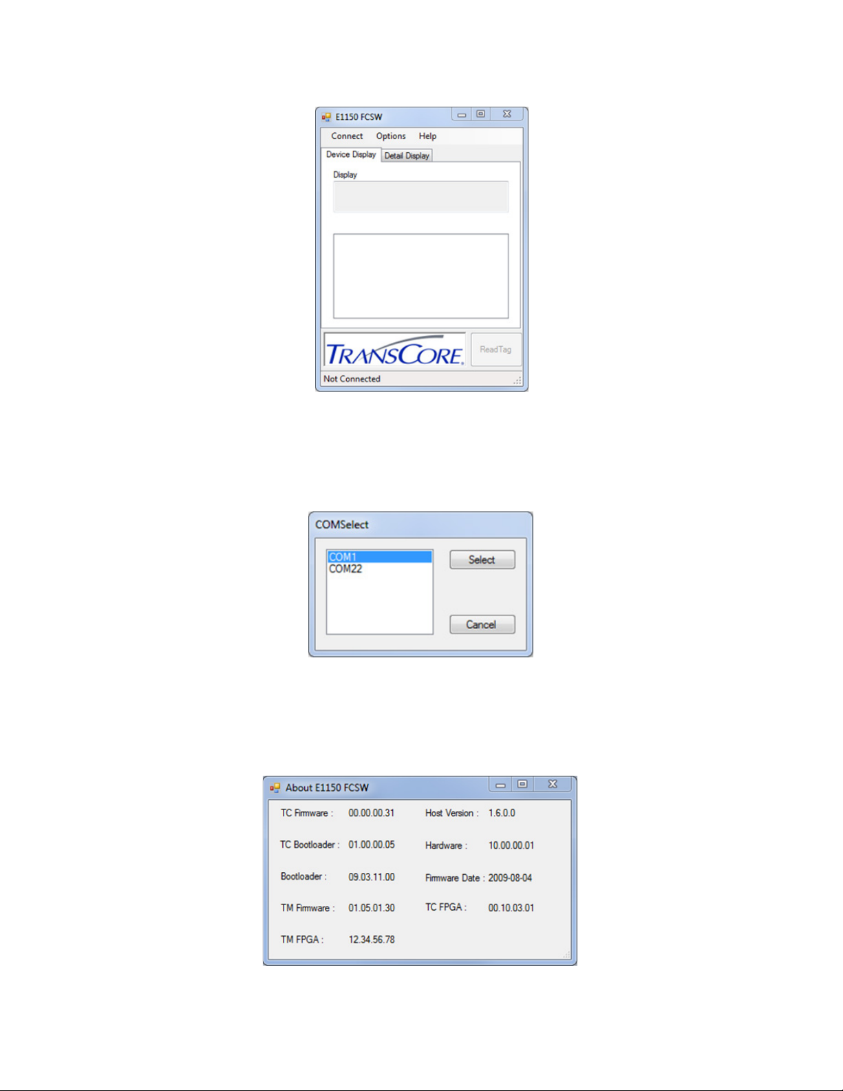
Start the E1150 Field Configuration Software
1. Launch the field configuration software via the desktop shortcut icon.
2. The E1150 FCSW startup window will open (Figure 1). Click Connect. Click COM Port.

Page 3
E1150 Mobile Reader
3. Select the associated COM port from the COMSelect window (Figure 2). Click SELECT. Observe that
the connect status in the lower left corner of the E1150 FCSW window reads Connected.
4. To view the FCSW and E1150 Version information, click on Help and then About (Figure 3).
Note: The firmware version shown in Figure 3 is for example only. Your version information may be
dierent.
Figure 1 E1150 Field Configuration Software Startup Window
Figure 2 COM Port Selection Window
Figure 3 E1150 FCSW About Window

User Guide
Page 4
Configure the E1150 for Operation
Select Options, then Configuration in the FCSW window. Operation configuration parameters can be
changed via the Config window as shown in Figure 4. The configuration parameters are listed in the Tag
Conversion Code drop down menu as shown in Figure 5. Click Save after setting your options.
Figure 4 FCSW Default Configuration Window
Figure 5 FCSW Configuration Tag Conversion Code Choices

Page 5
E1150 Mobile Reader
Table 1 Configuration Window Parameters
Operational Parameter Description
Tag Conversion Code Used to define how the E1150 will display the retrieved
tag data. The default
parameter is AAR.
Display Timeout
Controls the amount of time available for displaying
data. The default is 3 seconds.
Other times may be
selected but operational time will be significantly
aected when the unit is running on
battery power.
Mode parameter Used to select the RFID protocol being used to read
tags. The default is ATA Mode.
Multi Mode
Used for reading tags from mixed tag populations
such as FDOT. The Multi-Protocol Pair is fixed to SeGo
& Allegro/T21 and cannot be changed.
Bluetooth Enable
Used when tethering the reader to a Bluetooth
connected device running a host application. The
default option is o.
Buzzer Enable Used to enable the audible signal on completion of a
successful read. The default option is on.
Buer Enable Used to enable the on-board E1150 tag buering
mode. The default option is o.
Reader Timeout The configuration parameter should be set to 3
seconds for proper operation.
Range
The configuration parameter may be changed to
conserve battery charge or optimize the read range
and will significantly aect operational time when
battery powered. The default option is Maximum.
Select the lowest possible range setting that works
reliably with your tags and environment.

User Guide
Page 6
Reading Tags with the E1150
Place the Test Tag in front of the E1150 and push the Scan button located on the unit. Alternatively, from
the host computer, click the Read Tag button on the E1150 FCSW window (Figure 7). Both the E1150 and
the FCSW display window will show the decoded tag data based on the protocol and tag conversion code
configured in the unit. If you prefer a more detailed representation of the tag data, select the Detail
Display tab on the FCSW window, shown in Figure 8.
Figure 6 FCSW Configuration Mode Choices
Figure 7 FCSW Read Tag Results - Device Display

Page 7
E1150 Mobile Reader
Bluetooth Operation
With a user supplied USB Bluetooth®Adapter, a wireless Virtual COM port connection can be established
with
the E1150. Follow the manufacturer’s instructions for installation of a Virtual COM port connection to
the host
computer. Once a Bluetooth Virtual COM port connection is established with the Bluetooth dongle,
the field configuration software can be launched and used as before. The Bluetooth pairing number
required for the
E1150 is 1234.
Note: The connection to the E1150 is established using a virtual COM port. It is necessary to ensure
that only one E1150 is enabled and within range of the host computer at any one time. Multiple
Bluetooth connections are not supported through the virtual COM port.
Host Data Logging
To enable Host Data Logging, click Options, then Host Data Logging, and finally Activate Data Logging
(Figure 9). The E1150 will prompt for a save location for the logged data, then return to the Read Tag
Window. The E1150 FCSW is now logging all tag reads to the log file selected.
Note: Host Data Logging requires that the E1150 be connected to the PC (via USB or Bluetooth). If
the E1150 loses connection to the PC, the data log may become corrupted.
Figure 8 FCSW Read Tag Results - Detail Display

User Guide
Page 8
Onboard Tag Buering
The E1150 has the capability of Buering tag reads into internal memory. This buer is limited to the first
1001tags read after enabling Buering. To activate the buering capabilities of the E1150, select Buer
Enable in the FCSW Configuration.
To view the Buered Tags, select Options, then Buered Tags (Figure 10).
1 The tag buer for AAR is limited to the first 150 tags read after enabling Buering.
Figure 9 Activate Tag Logging
Figure 10 Activate Buered Tag View

Page 9
E1150 Mobile Reader
Once activated, the Buered Tag View (Figure 11) gives the option to download the E1150’s tag data buer.
Selecting the Buered button returns the amount of tags in the buer. By inputting a requested tag buer
number in the field below Get Log #, it is possible to retrieve a specific buered tag read. Get All returns all
tags in the buer, while Erase All empties the tag buer. Save allows the current displayed tag buer to be
saved to a log file, and Close closes the tag buer window.
Disconnect the E1150
Note: It is important to exit the software on the host computer before disconnecting the reader from
the system.
1. Exit the software on the host computer before you disconnect the reader. Click Disconnect in the
E1150 FCSW Window. Observe that the status on the lower left corner of the window reads Not
Connected.
2. Click the X on the upper right corner of the window to exit the software.
3. Disconnect the E1150 reader from the host PC.
Firmware Update
Do not attempt to update the firmware unless you have obtained an ocial firmware upload file from
TransCore. Save this firmware download file to a known location on your computer such as the Windows
desktop.
Firmware is updated via the Option tab under Firmware Upload.
Select Option > Firmware Upload.
Figure 11 Buered Tag View

User Guide
Page 10
A file explorer window will open. Navigate to the location of the firmware *.hex file (Figure 12).
Allow the process to complete. Exit the program.
Diagnostics
Note: Opening the E1150 case will damage the unit and void any warranties.
Should you encounter trouble when using the E1150 Mobile Reader, perform the following diagnostic
steps:
1. Ensure that the unit is adequately charged, or fully charge the unit.
2. Reposition the tag closer to the front area of the unit and try reading again.
3. Isolate the tag from other tags which might be interfering and try reading again.
4. If steps 1 and 2 do not correct the problem, uninstall then reinstall the host software on the host
computer. If steps 1 through 3 do not correct the problem, contact TransCore technical support for
further assistance.
Figure 12 Updating Firmware

Page 11
E1150 Mobile Reader
Regulatory and Compliance
FCC RADIO FREQUENCY INTERFERENCE STATEMENT
47 CFR §15.105(a)
Note: This equipment has been tested and found to comply with the limits for a Class A digital
device, pursuant to part 15 of the FCC Rules. These limits are designed to provide reasonable
protection against harmful interference in a residential installation. This equipment generates,
uses and can radiate radio frequency (RF) energy and may cause harmful interference to radio
communications if not installed and used in accordance with the instruction manual.
Operating this equipment in a residential area is likely to cause harmful interference, in which case,
depending on the regulations in eect, the users may be required to correct the interference at
their own expense.
This equipment has been tested and found to comply with the limits for a Class A digital device, pursuant
to Part 15 of the FCC Rules, and Industry Canada license-exempt RSS standard(s).
Operation is subject to the following two conditions: (1) This device may not cause harmful interference,
and (2) this device must accept any interference received, including interference that may cause
undesired operation.
Le présent appareil est conforme aux CNR d’Industrie Canada applicables aux appareils radio
exempts de licence. L’exploitation est autorisée aux deux conditions suivantes : (1) l’appareil
ne doit pas produire de brouillage, et (2) l’utilisateur de l’appareil doit accepter tout brouillage
radioélectrique subi, même si le brouillage est susceptible d’en compromettre le fonctionnement.
NO UNAUTHORIZED MODIFICATIONS
47 CFR §15.21
CAUTION: The equipment may not be modified, altered, or changed in any way without
permission from TransCore, LP. Unauthorized modification may void the equipment authorization
from the FCC and will void the TransCore warranty.
TransCore LP

For more information:
Sales Support
800.923.4824
Technical Support
505.856.8007
transcore.com
Trusted Transportation Solutions
© 2015-2020 TransCore L.P. All rights reserved. TRANSCORE is a registered trademark,
and is used under license. All other trademarks listed are the property of their respective
owners. Contents subject to change. Printed in the U.S.A.
Table of contents
Other TransCore RFID System manuals