Transfer Oil GOMAX QUADRA DN2 Installation guide

File name: Documento1
Last modify: 2021-04-16
Document Ref: MDTECH001
Page 1 of 8
Transfer Oil Assembling Instructions
GOMAX® QUADRA DN2 –DN4 –DN6
Scope
The scope of this training procedure is to train operators in assembling QUADRA DN2, DN4, DN6
hoses and fittings using a conventional/commercial hydraulic crimping machine, in addition to our
customized tools RXA007, RXA005, RXA011, RXA012 in order to provide advice for those customers
who need a heavy duty crimping machine.
It isessential to fulfil the training process in thehoseassemblyprocedures in order tomake high quality
Transfer Oil –GOMAX QUADRA DN2, DN4 and DN6 hose assemblies.
Transfer Oil –GOMAX QUADRA hose assemblies are designed and manufactured to be installed in
air conditioning & refrigeration applications.
Only the use of genuine Transfer Oil –GOMAX QUADRA hoses, fittings, recommended tooling and
full compliance with the following Transfer Oil –GOMAX QUADRA assembly instructions can
guarantee safety and conformity with standards.
WARNING!
NON-COMPLIANCE WITH THESE RULES CAN LEAD TO THE PREMATURE FAILURE OF THE HOSE
ASSEMBLY AND THE LOSS OF WARRANTY.

File name: Documento1
Last modify: 2021-04-16
Document Ref: MDTECH001
Page 2 of 8
The information contained in this document is the sole property of Transfer Oil S.p.A.
Any disclosure, copying or reproduction in part or as a whole of the information without the written permission of Transfer Oil S.p.A. is prohibited.
Extra care is taken in the preparation of this data sheet but Transfer Oil is not responsible for any inadvertent typographical errors or omissions. Information subject to change without
notice. The information in these instructions are only accurate as of the date of publication.
Contents
Scope.......................................................................................................................................................1
Crimping machine selection..........................................................................................................3
1.1. Selection of the crimping machine: ....................................................................................3
1.2. Selection of the dies:.............................................................................................................4
Preparing the assembly................................................................................................................5
Assembling the ferrule and the insert...........................................................................................5
Crimping of the ferrules ................................................................................................................6
4.1. Setting the crimping machine:...............................................................................................6
4.2. Crimping:................................................................................................................................6
Checking.......................................................................................................................................7
File name: Documento1
Last modify: 2021-04-16
Document Ref: MDTECH001
Page 3 of 8
Crimping machine selection
1.1. Selection of the crimping machine:
The crimping machine is the most important machine you will need when assembling GOMAX
QUADRA hoses DN2, DN4, DN6. For this reason it isvery important that the selection of this equipment
is made carefully, taking into account every characteristic of the parts that will be assembled and the
performance of the finished product.
For the assembling of the GOMAX QUADRA hoses DN2, DN4, DN6 with the GOMAX Quadra fitting
and ferrules there are many different hydraulic crimping machines available on the market; some
manufacturers and models of suitable hydraulic crimping machines are listed below.
•UNIFLEX –HYDRAULIC GmbH, model HM200;
•FINN POWER, model P20;
•O+P S.r.l, model TUBOMATIC H47/E EL.
This is just a short list of the suitable crimping machines that can be found on the market.
The two main characteristics that are fundamental to obtain a perfect crimping result on
GOMAX QUADRA assemblies are:
•the selected crimping machine SHOULD have 8 crimping dies;
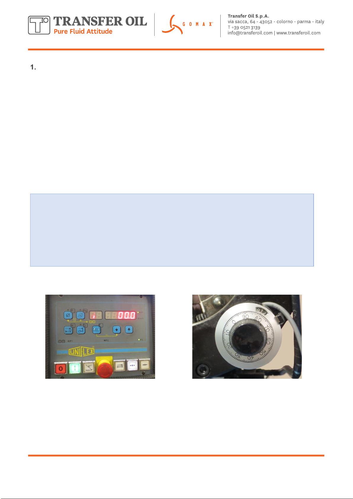
•the selected crimping machine SHOULD have a control for the position of the
dies: this control can be digital with a display for the crimping data or a simpler
electro mechanical vernier dial for setting the final position of the dies during the
crimping stroke.
Digital Control
Electro Mechanical control with vernier dial

File name: Documento1
Last modify: 2021-04-16
Document Ref: MDTECH001
Page 4 of 8
1.2. Selection of the dies:
The selected crimping machine should be equipped with 3 set of dies:
Set of dies diameter 6,8 mm for GOMAX QUADRA DN2.
Set of dies diameter 9,0 mm for GOMAX QUADRA DN4.
Set of dies diameter 12,0 mm for GOMAX QUADRA DN6.
In order to obtain a correct final crimping diameter, which is fundamental to ensure the performance of
the assembled hose, the correct die set should be installed on the crimping machine which should be
set to achieve the final diameter of the crimped ferrule as listed in the table below (Table 1).
The die sets diameters indicated in table 1 are those specified for the crimping machine as used by
Transfer Oil for the production of GOMAX QUADRA hose assemblies. If the indicated die sets are not
available for the customers selected crimping machine then, before ordering the selected crimping
machine, please contact Transfer Oil Customer Service.
The use of inadequate dies sets, for example too small, will result in irregular shape and ridges on the
external surface of the ferrule and the assembly will not be able to sustain the pressure.
The use of a die set too big will cause the incapability of reaching the final crimping diameter of the
ferrule.
If among the dies available for your machine you are missing the suitable one, please don’t attempt to
crimp the fitting regardless, contact your assembling machine dealer to supply the missing die set.
HOSE
DIES SET Diameter
(mm)
CRIMPING Diameter (mm)
DN2
6,8
7,0 ± 0,1mm
DN4
9.0
10,0 ± 0,1mm
DN6
12,0
12,4 ± 0,1mm
Table 1
File name: Documento1
Last modify: 2021-04-16
Document Ref: MDTECH001
Page 5 of 8
Preparing the assembly
Cut the GOMAX QUADRA capillary hose to the required
length using Transfer Oil cutter for capillary hoses type
WXA004. If you wish to use another method of cutting it is
important that the cut is perpendicular (90° angle with a
tolerance of 5%)
We recommended the use of the cutter WXA004.
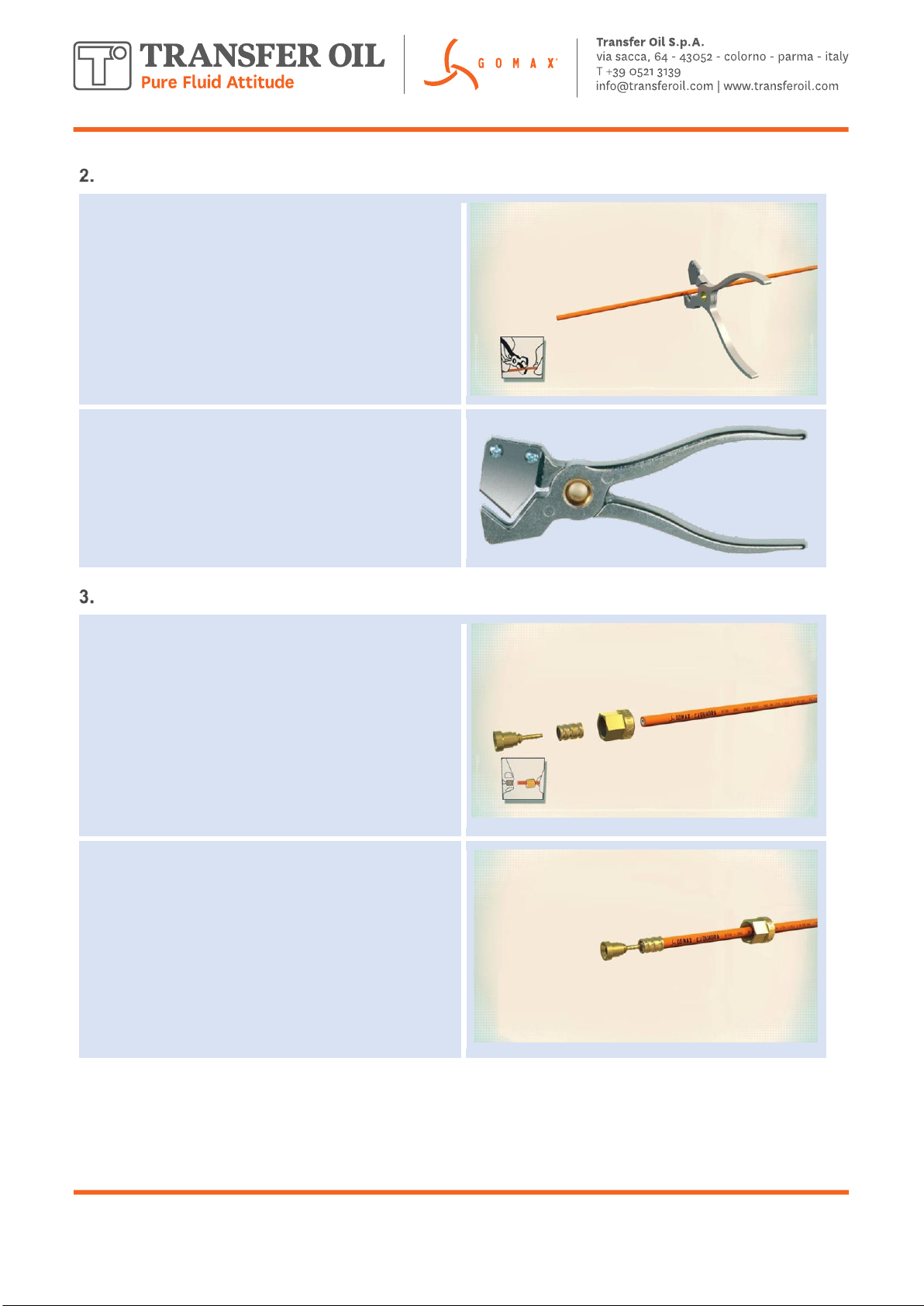
Assembling the ferrule and the insert
Slip the nut over the hose (depending on fitting type).
Ensure that the threaded side is pointing towards the end
of the hose that needs assembling.
Slip the ferrule over the hose end, ensure correct
positioning, in line with the hose end (due to the design it
can be only be mounted in one way).
Push the insert into the hose end you want to assemble.
Assemble/put the insert together with the nut onto the hose
end.
This manual suits for next models
2
Table of contents


