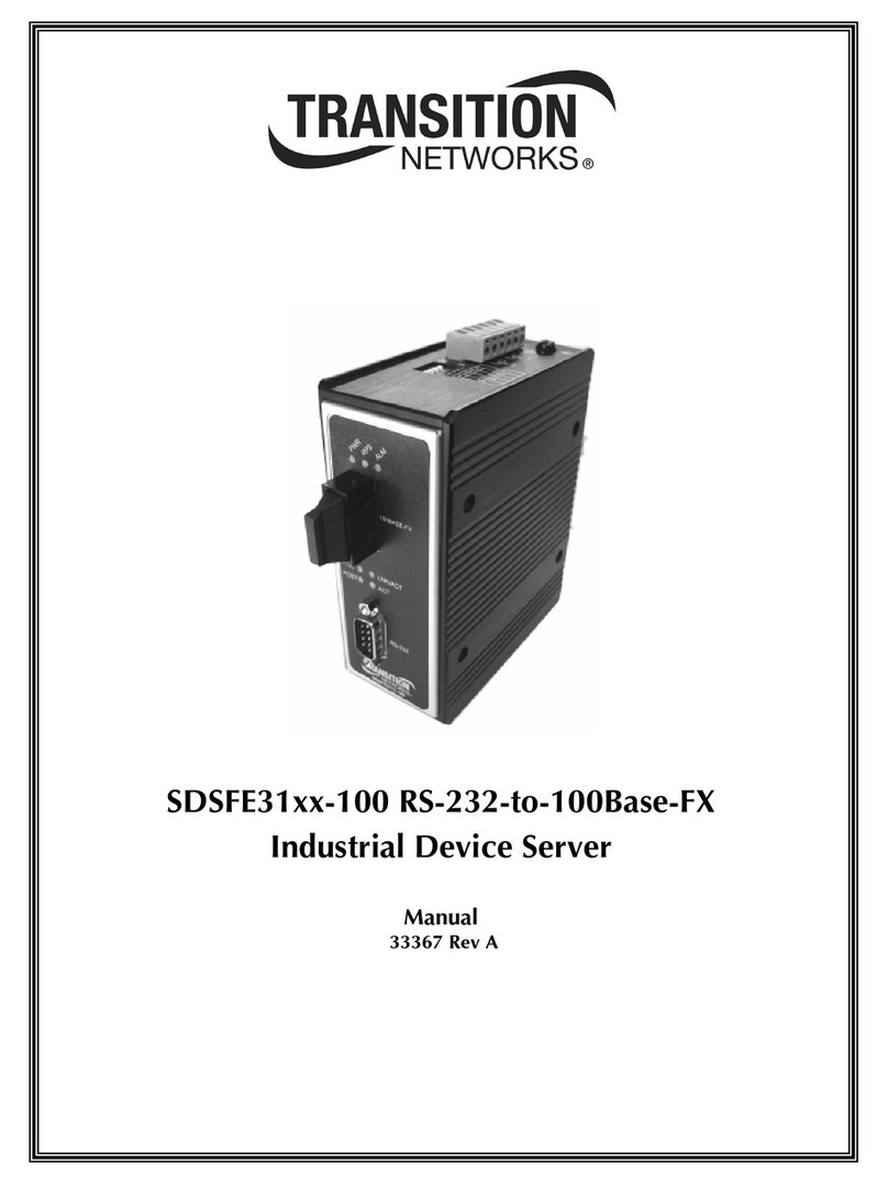
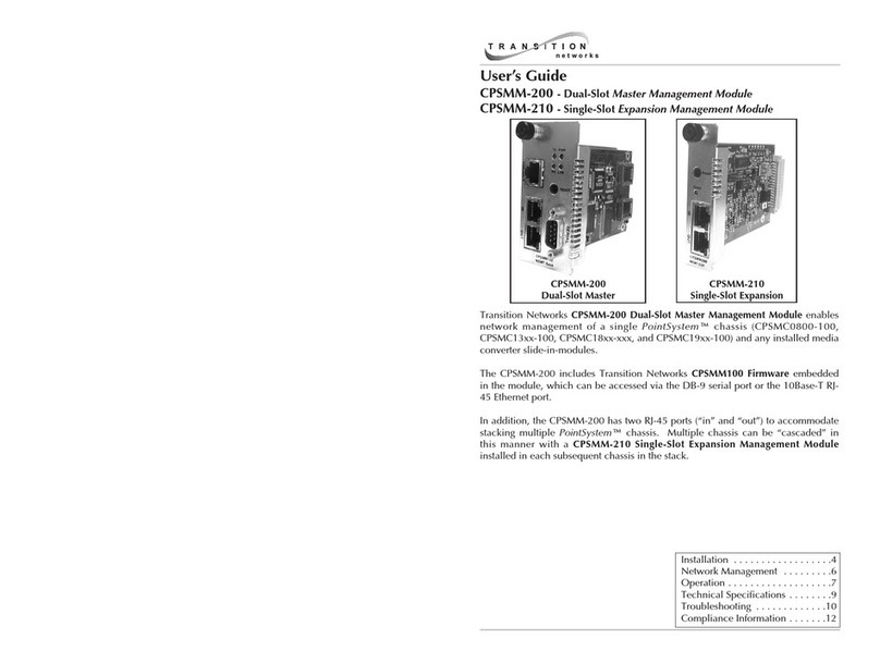
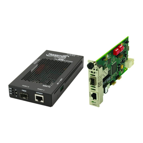
Transition Networks SwitchMaster MSB-E6/X2 User manual

SwitchMaster™or SwitchMasterFL™
Eight Segment Bridge
(MSB-E6/X2 or MSB-EFL6/X2)
7341.D
For assistance in installing, using, or
maintaining the TRANSITION Networks
SwitchMaster™ Eight Segment Bridge,
contact TRANSITION Networks Technical
Support at:
(800) 260-1312
or contact your local distributor.

CAUTION: RJ connectors are NOT INTENDED FOR
CONNECTION TO THE PUBLIC TELEPHONE NETWORK.
Failure to observe this caution could result in damage to the
public telephone network.
Compliance Information
UL Listed
C-UL Listed (Canada)
CISPR/EN55022 Class A
FCC Regulations
This equipment has been tested and found to comply with the limits for a class
A digital device, pursuant to part 15 of the FCC rules. These limits are
designed to provide reasonable protection against harmful interference when
the equipment is operated in a commercial environment. This equipment
generates, uses, and can radiate radio frequency energy and, if not installed
and used in accordance with the instruction manual, may cause harmful
interference to radio communications. Operation of this equipment in a
residential area is likely to cause harmful interference, in which case the user
will be required to correct the interference at the user’s own expense.
Canadian Regulations
This digital apparatus does not exceed the Class A limits for radio noise for
digital apparatus set out on the radio interference regulations of the Canadian
Department of Communications.
European Regulations
Warning
This is a Class A product. In a domestic environment this product may cause
radio interference in which case the user may be required to take adequate
measures.
Copyright Restrictions
© 1995, 1997 TRANSITION Networks.
All rights reserved. No part of this work may be reproduced or used in any
form or by any means – graphic, electronic, or mechanical – without written
permission from TRANSITION Networks.
Trademark Notice
All registered trademarks and trademarks are the property of their respective
owners.
Der Anschluss dieses Gerätes an ein öffentlickes
Telekommunikationsnetz in den EG-Mitgliedstaaten verstösst gegen die
jeweligen einzelstaatlichen Gesetze zur Anwendung der Richtlinie
91/263/EWG zur Angleichung der Rechtsvorschriften der
Mitgliedstaaten über Telekommunikationsendeinrichtungen
einschliesslich der gegenseitigen Anerkennung ihrer Konformität.

Table of Contents
Preface . . . . . . . . . . . . . . . . . . . . . . . . . . . . . . . . . . . . . . . . . . . . . . . . . . . . iii
1. INTRODUCTION . . . . . . . . . . . . . . . . . . . . . . . . . . . . . . . . . . . . . . . . . . . . 1–1
1.1 About Bridges. . . . . . . . . . . . . . . . . . . . . . . . . . . . . . . . . . . . . . . . . . . 1–2
Store and Forward . . . . . . . . . . . . . . . . . . . . . . . . . . . . . . . . . . . . 1–4
Learn Addresses. . . . . . . . . . . . . . . . . . . . . . . . . . . . . . . . . . . . . . 1–6
Age Addresses . . . . . . . . . . . . . . . . . . . . . . . . . . . . . . . . . . . . . . . 1–8
Participate in “Spanning Tree” . . . . . . . . . . . . . . . . . . . . . . . . . . 1–10
1.2 The SwitchMaster™ Eight Segment Bridge. . . . . . . . . . . . . . . . . . . . 1–12
1.3 SwitchMasterFL Eight Segment Bridges . . . . . . . . . . . . . . . . . . . . . . 1–16
1.3 SwitchMaster™ Bridge X Slot Cards. . . . . . . . . . . . . . . . . . . . . . . . . 1–18
Full Duplex Ethernet X Slot Card . . . . . . . . . . . . . . . . . . . . . . . . 1–18
100BaseT X Slot Card. . . . . . . . . . . . . . . . . . . . . . . . . . . . . . . . . 1–19
2. SITE PLANNING . . . . . . . . . . . . . . . . . . . . . . . . . . . . . . . . . . . . . . . . . . . . . 2–1
2.1 Site Considerations. . . . . . . . . . . . . . . . . . . . . . . . . . . . . . . . . . . . . . . 2–1
2.2 Ethernet Network Considerations . . . . . . . . . . . . . . . . . . . . . . . . . . . .2–1
3. INSTALLATION . . . . . . . . . . . . . . . . . . . . . . . . . . . . . . . . . . . . . . . . . . . . .3–1
3.1 Unpacking the SwitchMaster™ Bridge . . . . . . . . . . . . . . . . . . . . . . . .3-1
3.2 Installing in Rack or on Table . . . . . . . . . . . . . . . . . . . . . . . . . . . . . . .3-2
Standard 19-Inch Rack Installation . . . . . . . . . . . . . . . . . . . . . . . . 3-2
Table-Top Installation. . . . . . . . . . . . . . . . . . . . . . . . . . . . . . . . . . 3-3
3.3 Connecting to Network . . . . . . . . . . . . . . . . . . . . . . . . . . . . . . . . . . . .3-4
Connecting to 10BaseT at RJ-45 Connectors. . . . . . . . . . . . . . . . . 3-4
Optionally Connecting the AUI . . . . . . . . . . . . . . . . . . . . . . . . . . 3-6
3.4 Connecting to Power . . . . . . . . . . . . . . . . . . . . . . . . . . . . . . . . . . . . . .3-7
4. OPERATION . . . . . . . . . . . . . . . . . . . . . . . . . . . . . . . . . . . . . . . . . . . . . . . .4–1
4.1 Power On/Power Off . . . . . . . . . . . . . . . . . . . . . . . . . . . . . . . . . . . . .4–1
4.2 Monitoring SwitchMaster™ Bridge Operation . . . . . . . . . . . . . . . . . .4-2
Monitoring Bridge Status LEDs during Operation . . . . . . . . . . . . . 4-2
Monitoring Segment Status LEDs. . . . . . . . . . . . . . . . . . . . . . . . . . 4-5
5. MAINTENANCE . . . . . . . . . . . . . . . . . . . . . . . . . . . . . . . . . . . . . . . . . . . . .5–1
i
EIGHT SEGMENT BRIDGE
5.1 SwitchMaster™ BridgeFault Isolation Table . . . . . . . . . . . . . . . . . . . .5–2
5.2 Recovery Procedures . . . . . . . . . . . . . . . . . . . . . . . . . . . . . . . . . . . . .5–4
5.3 SwitchMaster™ Bridge Replacement Procedures . . . . . . . . . . . . . . .5–11
Replacing SwitchMaster™ Bridge Fuses. . . . . . . . . . . . . . . . . . . 5–11
5.4 SwitchMaster™ Field Upgrades . . . . . . . . . . . . . . . . . . . . . . . . . . . .5–12
Downloading Updated Software . . . . . . . . . . . . . . . . . . . . . . . . 5–12
Installing X Slot Card in SwitchMaster™ Bridge . . . . . . . . . . . . . 5-15
Appendix A. Technical Specifications . . . . . . . . . . . . . . . . . . . . . . . . . . . . . . .A–1
Appendix B. Cable Specifications . . . . . . . . . . . . . . . . . . . . . . . . . . . . . . . . . .B–1
Appendix C. Segment Distance . . . . . . . . . . . . . . . . . . . . . . . . . . . . . . . . . . . .C–1
Appendix D. Approved European Power Cord Set . . . . . . . . . . . . . . . . . . . . .D–1
Appendix E. Policy and Procedure . . . . . . . . . . . . . . . . . . . . . . . . . . . . . . . . .E–1
ii SwitchMaster™/SwitchMasterFL™

Preface
This guide is intended for the system or network administrator responsible
for installing, configuring, using, and maintaining a Transition Networks
SwitchMaster™ Eight Segment Bridge. A working knowledge of local area
network (LAN) operations, including familiarity with communications
protocols used on interconnected LANs, is assumed.
iii
EIGHT SEGMENT BRIDGE


EIGHT SEGMENT BRIDGE
1. INTRODUCTION
The SwitchMaster™ Eight Segment Bridge is a multi-segment Ethernet
bridge that provides six RJ-45 ports (with one alternate AUI connector)
with installation space for two additional X Slot multi-media connections.
The SwitchMasterFL™ Eight Segment Bridge is a multi-segment Ethernet
bridge that provides six (6) pairs of fiber transmit (TX) and receive (RX)
data connectors with installation space for two additional X Slot multi-
media connections.
As shipped, either the SwitchMaster™ or the SwitchMasterFL™ Eight
Segment Bridge is a fully functional bridge that can be used for connecting
and/or for isolating Ethernet networks. Bridge ports can be set individually
to full or half duplex.
The optional X Slot cards , if installed, provide either an AUI transceiver
network connection or an RJ-45 connection to 10BaseT and/or an RJ-45
connection to 100BaseTX.
1-1
Status
Power
X Slot 2
™
Eight Segment Bridge
Serial
Reset
X Slot 1
networks
TRANSITION SwitchMaster
Segment 1 Segment 2 Segment 3 Segment 4 Segment 5 Segment 6
AUI
RX
COL
LINK
TX
RX
COL
LINK
TX
RX
COL
LINK
TX
RX
COL
LINK
TX
RX
COL
LINK
TX
RX
COL
LINK
TX
SwitchMaster FL
Status
RX
COL
LINK
TX
RX TX
Segment 1
Power
X Slot 2
™
Eight Segment Bridge
Serial
Reset
X Slot 1
networks
TRANSITION
RX
RX
COL
LINK
TX
RX TX
Segment 2
RX
COL
LINK
TX
RX TX
Segment 3
RX
COL
LINK
TX
RX TX
Segment 4
RX
COL
LINK
TX
RX TX
Segment 5
RX
COL
LINK
TX
RX TX
Segment 6

SwitchMaster™/SwitchMasterFL™
1.1 About Bridges
A bridge is a network device that can be used to merge two or more Local
Area Networks (LANs) into a single functional LAN or, alternatively, to
separate a single LAN into two or more functional LANs.
The bridge is used to merge two or more LANs into a single functional
LAN for:
• increasing reliable distances between stations, particularly in Ethernet
environments
• connecting different media types.
The bridge is used to separate one LAN into two or more functional LANs
for:
• increasing available bandwidth by decreasing station contention
• decreasing delays caused by multiple stations
• isolating LAN failures.
These contradictory objectives are achieved because the bridge receives
and stores data packets from all stations on attached LANs, then forwards
the data packets to all other stations on all other attached LANs. Because
the bridge forwards data packets from one LAN to another, stations on the
sending LAN can communicate with receiving stations on other LANs,
merging the LANs into one functional LAN. Because the bridge stores
received data packets, transmission of data packets from one LAN to
another is not controlled by the sending or receiving LAN, functionally
separating the LANs.
A bridge is an ISO/OSI Model Layer 2 Data Link relay. The ISO/OSI Data
Link layer transmits data packets from a source across a link to a peer
destination. The data link layer transmits data across the link by
interfacing with the physical layer (the transmission line and connectors)
at each end of the link.
1-2
LAYER 7
LAYER 6
LAYER 5
LAYER 4
LAYER 3
LAYER 2
LAYER 1
Data Link
Network
Physical
LAYER 7
LAYER 6
LAYER 5
LAYER 4
LAYER 3
LAYER 2
LAYER 1
Data Link
Network
Physical
BRIDGE CONNECTION

EIGHT SEGMENT BRIDGE
1. INTRODUCTION
1-3
Remote, unattached LAN
Large, slow LAN
Smaller, faster LAN #2
BRIDGE #1
Smaller, faster LAN #3
Smaller, faster LAN #1
Attached LAN
BRIDGE #2
BRIDGE #3

SwitchMaster™/SwitchMasterFL™
According to the IEEE 802.1d specification, bridges must:
• Store and Forward
• Learn Addresses
• Age Addresses
• Participate in “Spanning Tree”
Store and Forward
A data packet sent out on a LAN is received by the bridge, which stores
the data packet exactly as received. Later, when there is no traffic on the
LAN, the bridge sends the data packet out, either on the destination LAN
or on all LANs other than the LAN on which the data packet was received.
A possible sequence of events is:
1. Source #1 sends data packet intended for destination #1.
2. Bridge copies data packet #1 and waits.
3. Source #2 sends data packet intended for destination #2.
4. Bridge copies data packet #2 and waits.
5. Source #3 sends data packet intended for destination #3 on same
LAN.
6. Destination #3 receives data packet #3.
7. Bridge discards (filters) data packet #3.
8. Bridge sends data packet #1 for unknown destination #1 over all
LANs except LAN from which data packet # was received.
9. Bridge sends data packet #2 for unknown destination #2 over all
LANs except LAN from which data packet #2 was received.
10. Destination #1 receives data packet #1.
11. Destination #2 receives data packet #2.
1-4

1. INTRODUCTION
1-5
EIGHT SEGMENT BRIDGE
Destination #2
Destination #1
Source #2
1
Source #1
Packet #1 Packet #1
Bridge
Source #3
Destination #3
5
3
24
6
11
10
9
78
8
8
8
9
9
9

SwitchMaster™/SwitchMasterFL™
Learn Addresses
When a data packet is received by the bridge, the source identifier and
LAN are copied from the packet header and stored in the address cache.
Then, when later packets are received, the bridge compares the
destination identifier of the received packet with cache addresses. If a
match is found, the bridge “knows”the destination LAN and sends the
data packet out only on the known destination LAN.
A possible sequence of events is:
1. Source #1 sends data packet intended for destination #1.
2. Bridge copies data packet #1 with source identifier and LAN into
cache, then waits.
3. Source #2 sends data packet intended for destination #2.
4. Bridge copies data packet #2 with source identifier and LAN into
cache, then waits.
5. Source #3 sends data packet intended for destination #3.
6. Bridge copies data packet #3 with source identifier and LAN into
cache, then “knows”destination #3 as source #1.
7. Bridge sends data packet #1 for unknown destination #1 over all
LANs except LAN from which data packet #1 was received.
8. Bridge sends data packet #2 for unknown destination #2 over all
LANs except LAN from which data packet #2 was received.
9. Bridge sends data packet #3 for destination #3 (also source #1)
over destination #3 /source #1 LAN.
10. Destination #1 receives data packet #1.
11. Destination #2 receives data packet #2.
12. Destination #3 receives data packet #3.
1-6

1. INTRODUCTION
1-7
EIGHT SEGMENT BRIDGE
Bridge
Destination #2
Destination #1
Source #2
Source #1
Source #3
Destination #2
1
5
3
11
7
89
7
7
7
12
10
8
8
8
Packet #1
Packet #1
Address Cache
source 1
source 2
source 3
source 4
source 5
LAN 1
LAN 2
LAN 3
LAN 4
LAN 5
2
6
4

SwitchMaster™/SwitchMasterFL™
Age Addresses
When a data source identifier is copied from a packet header into the
address cache, the bridge compares the destination identifier of the
received packet with cache addresses. If a match is found, the bridge
“knows”the destination LAN and sends the data packet only on the
known destination LAN. LANs which neither send nor receive data
packets for a defined period of time are “aged”, or eliminated from cache
memory.
A possible sequence of events, as shown, is:
1. Source #1 sends data packet intended for destination #1.
2. Bridge copies data packet #1 with source identifier and LAN into
cache.
3. Bridge deletes oldest source identifier #2 and LAN from cache,
then waits.
4. Source #2 sends data packet intended for destination #2.
5. Bridge copies data packet #2 with newest source identifier and
LAN into cache.
6. Bridge sends data packet #1 for unknown destination #1 over all
LANs except LAN from which data packet #1 was received.
7. Bridge sends data packet #2 for unknown destination #2 over all
LANs except LAN from which data packet #2 was received.
8. Destination #1 receives data packet #1.
9. Destination #2 receives data packet #2.
1-8

1. INTRODUCTION
1-9
EIGHT SEGMENT BRIDGE
Bridge
Destination #1
Source #2
Source #1
Packet #1
Packet #1
Address Cache
Source #3
Destination #2
1
3
2
4
6
7
8
9
7
source 1
source 2
source 3
source 4
source 5
LAN 1
LAN 2
LAN 3
LAN 4
LAN 5
5
6
6
6
77

SwitchMaster™/SwitchMasterFL™
1-10
Participate In “Spanning Tree”
The spanning tree algorithm is intended to prevent LAN failure caused by
the unintended generation of infinite broadcast loops.
Infinite Loops
Since bridges forward data packets across all LANs except the LAN from
which the data packet is received, and since bridges are transparent to all
other bridges, when multiple bridges connect multiple LANs, infinite
loops can be generated by situations such as the following:
1. Source #1 sends data packet intended for destination #1 on LAN
#1.
2. Bridge #1 and Bridge #2 copy data packet #1, with LAN #1
identifier, into cache.
3. Randomly, Bridge #1 responds before Bridge #2. Bridge #1 sends
data packet #1 out onto LAN #2.
4. Destination #1 receives data packet #1.
5. Bridge #2 sends data packet #1 on LAN #2.
6. Bridge #2 receives data packet #1 on LAN #2 and copies data
packet #1, with LAN #2 identifier, into cache.
7. Bridge #1 receives data packet #1on LAN #2 and copies data
packet #1, with LAN #2 identifier, into cache.
8. Bridge #2 sends data packet #1 on LAN #1.
9. Bridge #1 sends data packet #1 on LAN #1.
10. Bridge #2 receives data packet #1 on LAN #1 and copies data
packet #1, with LAN #1 identifier, into cache.
11. Bridge #1 receives data packet #1on LAN #1 and copies data
packet #1, with LAN #1 identifier, into cache.
12. Bridge #1 sends data packet #1 out on LAN #2.
13. Bridge #2 sends data packet #1 on LAN #2.
AND SO ON. . . .

1. INTRODUCTION
1-11
EIGHT SEGMENT BRIDGE
The “Spanning Tree”Algorithm
The “Spanning Tree”algorithm avoids the generation of infinite loops by
dynamically defining one and only one direct logical path between any
two bridged LANs.
The spanning tree algorithm uses the fields:
root identifier
cost to root
transmitter
to dynamically identify one “root”bridge for each network and one
designated LAN bridge for each LAN on the network.
LAN #2
Destination #1
LAN #1
Source #1
1
4
Bridge #1 Bridge #2
Packet #1
Address Cache
source 1
source 1
source 1
source 1
LAN 1
LAN 2
LAN 1
LAN 2
Packet #1
Address Cache
source 1
source 1
source 1
source 1
LAN 1
LAN 2
LAN 1
LAN 2
9
2
7
12
5
3
2
6
11 10
8
13

1.2 The SwitchMaster™ Eight Segment Bridge
The SwitchMaster™Eight Segment Bridge provides six RJ-45 port
connectors (with one alternate AUI connector), a DB9 serial port
connector, LED status indicators, and a reset switch.
Connectors
Six (6) RJ-45 connectors, a DB9 serial port connector, and an AUI port
connector are provided at the front of the SwitchMaster™Eight Segment
Bridge.
Two additional spaces are provided at the front of the SwitchMaster™
Eight Segment Bridge for installation of “X”Slot cards.
NOTE: A power connector is provided at the back of the SwitchMaster™
Bridge.
Switches
The reset switch reinitializes the SwitchMaster™Eight Segment Bridge.
1-12 SwitchMaster™/SwitchMasterFL™
TM
SwitchMaster
Eight Segment Bridge
Reset
Power Status Serial Segment 1 Segment 2 Segment 3 Segment 4 Segment 5 Segment 6
RX RX RX RX RX RX
TX TX TX TX TX TX
COL
LINK
COL
LINK
COL
LINK
COL
LINK
COL
LINK
COL
LINK
X Slot 2 X Slot 1
AUI
AUI
Serial
networks
TRANSITION
TM
SwitchMaster
Eight Segment Bridge
Reset
Power Status Serial Segment 1 Segment 2 Segment 3 Segment 4 Segment 5 Segment 6
RX RX RX RX RX RX
TX TX TX TX TX TX
COL
LINK
COL
LINK
COL
LINK
COL
LINK
COL
LINK
COL
LINK
X Slot 2 X Slot 1
AUI
Reset
networks
TRANSITION

Indicators
SWITCHMASTER™ POWER INDICATOR
When the SwitchMaster Eight Segment Bridge is powered, the Power
indicator is illuminated.
SWITCHMASTER™ STATUS INDICATORS
When the SwitchMaster™Eight Segment Bridge is functioning normally,
the eight Status indicators cycle in a steady roll.
NOTE: During power on, the eight Status indicators cycle through a
predefined diagnostic pattern.
SEGMENT 1 AUI STATUS INDICATORS
WhenSegment 1 is connected through the AUI connector, the Segment 1
status LEDs indicate AUI network activity.
1. INTRODUCTION
1-13
EIGHT SEGMENT BRIDGE
TM
SwitchMaster
Eight Segment Bridge
Reset
Power Status Serial Segment 1 Segment 2 Segment 3 Segment 4 Segment 5 Segment 6
RX RX RX RX RX RX
TX TX TX TX TX TX
COL
LINK
COL
LINK
COL
LINK
COL
LINK
COL
LINK
COL
LINK
X Slot 2 X Slot 1
AUI
Status
networks
TRANSITION
TM
SwitchMaster
Eight Segment Bridge
Reset
Power Status Serial Segment 1 Segment 2 Segment 3 Segment 4 Segment 5 Segment 6
RX RX RX RX RX RX
TX TX TX TX TX TX
COL
LINK
COL
LINK
COL
LINK
COL
LINK
COL
LINK
COL
LINK
X Slot 2 X Slot 1
AUI
RX
TX
COL
LINK
networks
TRANSITION
TM
SwitchMaster
Eight Segment Bridge
Reset
Power Status Serial Segment 1 Segment 2 Segment 3 Segment 4 Segment 5 Segment 6
RX RX RX RX RX RX
TX TX TX TX TX TX
COL
LINK
COL
LINK
COL
LINK
COL
LINK
COL
LINK
COL
LINK
X Slot 2 X Slot 1
AUI
Power
networks
TRANSITION

SEGMENT 1 RJ-45 STATUS INDICATORS
WhenSegment 1 is connected through the RJ-45 connector, the Segment 1
status LEDs indicate RJ-45 connection status.
SEGMENT 2-SEGMENT 6 RJ-45 STATUS INDICATORS
When Segment 2 through Segment 6 RJ-45 are connected, the Segment
status LEDs indicate RJ-45 connection status.
1-14 SwitchMaster™/SwitchMasterFL™
TM
SwitchMaster
Eight Segment Bridge
Reset
Power Status Serial Segment 1 Segment 2 Segment 3 Segment 4 Segment 5 Segment 6
RX RX RX RX RX RX
TX TX TX TX TX TX
COL
LINK
COL
LINK
COL
LINK
COL
LINK
COL
LINK
COL
LINK
X Slot 2 X Slot 1
AUI
RX
TX
COL
LINK
networks
TRANSITION
RX
TX
COL
LINK
This manual suits for next models
1
Table of contents
Other Transition Networks Network Hardware manuals

Transition Networks
Transition Networks ION x6010 User manual

Transition Networks
Transition Networks CPSMM-200 User manual

Transition Networks
Transition Networks SISPM1040-582-LRT User manual

Transition Networks
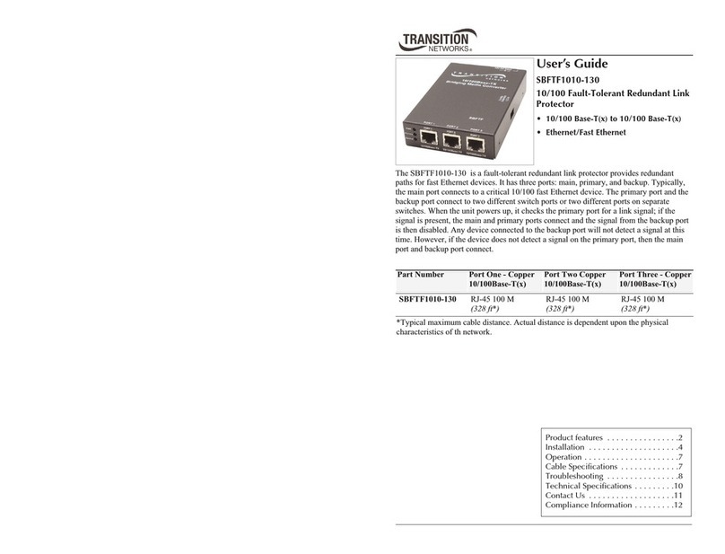
Transition Networks SBFTF1010-130 User manual

Transition Networks
Transition Networks INDUSTRIAL DEVICE SERVER SDSFE31XX-100 User manual