manuals.online logo
Brands
  1. Home
  2. •
  3. Brands
  4. •
  5. Fluke
  6. •
  7. Network Hardware
  8. •
  9. Fluke STAP-BT-4X16 User manual

Fluke STAP-BT-4X16 User manual

Unpacking
• (1) Quick Installation Guide
• (1) STAP-BT-4X16 16-Port Quad Output SPAN Tap
• (2) AC power cords
• (4) CAT 5E cables
• (2) USB-to-DB9F quad-control cable
• (1) USB Type-A cable
• (1) Switch Control Software CD
• (1) Hardware Guide
• (1) MANAgents Software Guide
Introduction
The STAP-BT-4X16 Copper SPAN Tap is a 16-port,
quad-output device that both increases your network
visibility and leverages your analyzers, probes and
security equipment by allowing you to monitor up
to four SPAN ports simultaneously. This improved
visibility accelerates network problem resolution,
reduces your downtime, increases productivity and
improves the bottom line.
FFEEAATTUURREESSAANNDDBBEENNEEFFIITTSS
• 10/100/1000BASE-T with standard RJ45 ports
• Leverage with a single STAP-BT-4X16 unit up
to four network applicances across a total of
16 SPAN or mirror ports
• Daisy-chain with standard USB cables up to
four STAP-BT-4X16 units to enable your network
access to a total of 64 SPAN or mirror ports
• Manage the Copper SPAN Tap either through
your monitoring device’s API or with Fluke
Networks MANAgents software
• Save network configuration schemes and
segment names with MANAgents software
• Reduce the need to travel on-site with
portable equipment using central management
• Standard 1U rack mount height and width
STAP-BT-4X16 Specifications
FFUUNNCCTTIIOONNAALLDDIIAAGGRRAAMM
Figure 1. STAP-BT-4X16 front panel display
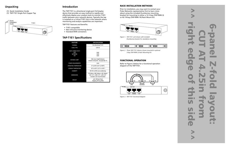
Refer to Figure 2 below for a connectivity diagram
of the STAP-BT-4X16 Copper SPAN Tap.
Figure 2. STAP-BT-4X16 functional application diagram
General Installation Notes
This quick reference guide is abbreviated for proficient
network technicians; detailed installation and configura-
tion steps are found in the Hardware Guide.
To connect the STAP-BT-4X16 to the network, refer
to Figure 2 and follow these steps:
1. Connect both power supplies to separate power
sources to eliminate power loss as a cause of failure.
The POWER 1 and 2LEDs will illuminate, indicating
that both power supplies are on. Either LED failing to
illuminate indicates a defective power source; replace
immediately to ensure redundant power integrity.
IMPORTANT
Do not exceed the maximum length of 100 meters
between end-points.
2. Connect one of the network cables from the
SPAN port on each network appliance to the
desired STAP-BT-4X16 NETWORK port connector.
NOTE
For NETWORK, TAP or DAISY RJ45 connectors,
integrated LEDs display line status and speed of each
port. See the LED Display Codes table.
3. Connect the TAP A RJ45 port on the Copper SPAN
Tap to the network appliance’s Network Interface
Card (NIC). The TAP A port will illuminate, indicating
link has been established. Repeat with TAP B, TAP C
and TAP D ports to other devices as needed.
4. Connect the MANAGEMENT port of the Copper
SPAN Tap to the network for remote console control.
Alternately, connect the CONTROL port to a local host
control console using the included quad-control cable.
5. After installation, the MANAgents software must be
installed on your management console. Please refer
to the MANAgents software guide for details.
LLEEDDDDIISSPPLLAAYYCCOODDEESS
UUPPPPEERRRRJJ4455PPOORRTTSS::LLOOCCKKTTAABBPPOOSSIITTIIOONNUUPPWWAARRDD
LLOOWWEERRRRJJ4455PPOORRTTSS::LLOOCCKKTTAABBPPOOSSIITTIIOONNDDOOWWNNWWAARRDD
6-panel Z-fold layout:
CUT AT 4.25in from
^^ right edge of this side ^^
Quick
Installation
Guide
MANAgents
Switch
Control
Server
software
Guide
CAT 5E
Cable x4
A
USB Cable
USB Cable-to-DB9F
Quad-Control Cable
C Power
Cable x2
STAP-BT-4X16
Copper SPAN Tap
Hardware
Guide
FEATURE SPECIFICATION
NUMBER OF PORTS
NETWORK
TAP
DAISY
Sixteen (16) Network ports
Four (4) Tap ports
Four (4) Daisy ports
LINK SPEED SUPPORT 10/100/1000BASE-T Ethernet
CABLE TYPE CAT 5E
PORT CONNECTIVITY
MANAGEMENT
CONTROL AND LINK
DAISY
TAP
RJ45
USB-style
RJ45
RJ45
DISTANCE LIMIT
100m max. length between
network end-points. (1m typical
length for network tools, up to 100m)
NOMINAL POWER REQUIREMENTS Two external power sources 100–240V AC
at 50–60Hz / 1.5A5V DC, 2A
OPERATING TEMPERATURE 0° to 40°C (32° to 104°F)
STORAGE TEMPERATURE -30° to 65°C (-22° to 149° )
HUMIDITY RH less than 95% non-condensing
DIMENSIONS
(H) 44mm x (W) 483mm x (D) 279mm
(H) 1.75" x (W) 19.00" x (D) 11.00"
(includes integral 19" rack mount brackets)
WEIGHT STAP-BT-4X16 unit: 4.99kg (11lbs)
shipping: 7.71kg (17lbs)
Network
IDS
Probe
INTERNET
DEPARTMENT A
DEPARTMENT C
DEPARTMENT D
Forensic
Recovery
Daisy-chain up
to 4 switches
to cover up to
64 SPAN ports
Protocol
Analyzer
Cables to
SPAN Port
of each
Ethernet
Switch
Cables to
SPAN Port
of each
Ethernet
Switch
IP addressable
10/100 transport
connection
Connect up to 4 network
tools and manage from
a single console
Management Console
with MANAgents
IP Network
DMZ
DEPARTMENT B
lower right [green] LED
INDICATOR FUNCTION
MODE
SOLID link
FLASHING data
upper left [green] LED
INDICATOR FUNCTION
MODE
SOLID link
FLASHING data
upper right LED
INDICATOR TRANSFER
RATE
GREEN 1,000Mbps
ORANGE 100Mbps
[OFF] 10Mbps
lower left LED
INDICATOR TRANSFER
RATE
GREEN 1,000Mbps
ORANGE 100Mbps
[OFF] 10Mbps
6-panel Z-fold layout:
CUT AT 4.25in from
^^ left edge of this side ^^
DDAAIISSYY--CCHHAAIINNCCOONNFFIIGGUURRAATTIIOONN
The address for each STAP-BT-4X16 Copper SPAN Tap in
a daisy-chain must be set up prior to installation. Refer to
the Fluke Networks MANAgents software for more details.
Figure 3. STAP-BT-4X16 daisy-chain control connectivity diagram
Follow these steps to make interconnection between
multiple Copper SPAN Taps and network device links:
1. Connect SPAN ports from each network device to
one of the NETWORK ports on the Copper SPAN Tap.
NOTE
The network monitor tool must match the selected
network duplex speed.
2. Connect the TAP A port on the first Copper SPAN
Tap to the network monitor tool. The TAP A link
LED will illuminate, indicating successful link is made.
3. Connect other TAP ports to other monitoring tools as
desired. Verify each link by referring to port LEDs.
4. Connect the DAISY A port on the first Copper
SPAN Tap to the TAP A port on the next Copper
SPAN Tap. The TAP A port LED will illuminate.
5. Repeat by connecting other DAISY ports on the
primary Copper SPAN Tap to the respective TAP
ports on the following Copper SPAN Tap.
6. To add more Copper SPAN Taps to the daisy-chain
configuration, repeat steps 4 and 5, connecting the
DAISY ports on the previously chained Copper SPAN
Tap to the respective TAP ports on the successive
Copper SPAN Tap.
7. Connect the MANAGEMENT port on the first Copper
SPAN Tap to the network for remote control, or con-
nect the CONTROL USB port of the first Copper SPAN
Tap to a local console using the quad-control cable.
8. Connect the LINK USB port on the first Copper SPAN
Tap to the CONTROL port on the next Copper SPAN
Tap. Repeat with any other daisy-chained Copper
SPAN Taps.
9. Once installation is complete, the switch control
software must be configured to your network. Refer
to the Fluke Networks MANAgents software guide
and STAP-BT-4X16 hardware guide for more details.
16-Port Quad Output
10/100/1000BASE-T
Copper SPAN Tap
SSTTAAPP--BBTT--44XX1166
QQUUIICCKKIINNSSTTAALLLLAATTIIOONNGGUUIIDDEE
PN 2576703
January 2006
© 2006 Fluke Corporation. All rights reserved. Printed in USA.
All product names are trademarks of their respective companies.
CCOONNTTAACCTTIINNGGFFLLUUKKEENNEETTWWOORRKKSS
Visit the Fluke Networks website
at www.flukenetworks.com.
Send email to: [email protected].
For operating assistance, sales, or service in the USA,
call 1-800-283-5853.
From other countries:
• Canada: 1-800-363-5853
• Europe: +44 1923 281 300
• Beijing: +86 (10) 6512-3435
• Japan: +81-3-3434-0181
• Singapore: +65-6738-5655
• Anywhere in the world: +1-425-446-4519
Visit our website for a complete list of phone numbers.
Limited Warranty & Limitation of Liability
Fluke Networks products will be free from defects in
material and workmanship for two years from the date
of purchase. Parts, accessories, product repairs and
services are warranted for 90 days. This warranty
does not cover disposable batteries, cable connector
tabs, cable insulation-displacement connectors, or
damage from accident, neglect, misuse, alteration,
contamination, or abnormal conditions of operation
or handling. Resellers are not authorized to extend
any other warranty on Fluke Networks’ behalf.
To obtain service during the warranty period, contact
your nearest Fluke Networks authorized service center
to obtain return authorization information, then send
your defective product to that Service Center with a
description of the problem.
THIS WARRANTY IS YOUR ONLY REMEDY.
NO OTHER WARRANTIES, SUCH AS FITNESS FOR
A PARTICULAR PURPOSE, ARE EXPRESSED OR IMPLIED.
FLUKE NETWORKS IS NOT LIABLE FOR ANY SPECIAL,
INDIRECT, INCIDENTAL OR CONSEQUENTIAL DAMAGES
OR LOSSES, ARISING FROM ANY CAUSE OR THEORY.
Since some states or countries do not allow the exclusion
or limitation of an implied warranty or of incidental or
consequential damages, this limitation of liability may
not apply to you.
FLUKE NETWORKS, INC. P.O. BOX 777 EVERETT, WA 98206-0777 USA
CCOOMMPPLLIIAANNCCEETTEESSTTIINNGG
CAUTION
Changes or modifications to this unit not expressly
approved by the party responsible for compliance
could void the user’s authority to operate the
equipment.
CCEERRTTIIFFIICCAATTIIOONNSS
This equipment has been tested and found to
meet the radiated and conducted emission limits for
a Class B product of EN 55022 to the EMC Directive
89/336/EEC requirements.
This equipment has been tested and found to meet
the immunity levels for Class 1, tested to level 2
for EN 6100-4-2, tested to level 3 for EN 61000-4-3,
tested to level 2 for EN 61000-4-4, and tested to
level 3 for EN 61000-4-5 to the EN 50082-1
requirements and meets the Class A requirements
for EN 61000-3-2 and EN 61000-3-3.
This equipment has completed the Product Safety
Review and found to meet the Low Voltage Directive
72/23/EEC (1993) requirements.
Cables to SPAN
Port of each
Ethernet Switch
Cables to SPAN
Port of each
Ethernet Switch
Cables to SPAN
Port of each
Ethernet Switch
IP addressable
10/100 transport
connection
Connect up to 4 network
tools and manage from
a single console
Management Console
with MANAgents
IP Network
Probe
Cables to SPAN
Port of each
Ethernet Switch

Other Fluke Network Hardware manuals

Fluke TAP-DS3E3 User manual

Fluke

Fluke TAP-DS3E3 User manual

Fluke TAP-100-2X16 Installation instructions

Fluke

Fluke TAP-100-2X16 Installation instructions

Fluke TAP-1000BT-BT User manual

Fluke

Fluke TAP-1000BT-BT User manual

Fluke TAP-1000BT-SX User manual

Fluke

Fluke TAP-1000BT-SX User manual

Fluke SimpliFiber Pro User manual

Fluke

Fluke SimpliFiber Pro User manual

Fluke NetDAQ 2640A User manual

Fluke

Fluke NetDAQ 2640A User manual

Fluke AXTAP1204BT-BT User manual

Fluke

Fluke AXTAP1204BT-BT User manual

Fluke Premium 3 User manual

Fluke

Fluke Premium 3 User manual

Fluke OneTouch AT User manual

Fluke

Fluke OneTouch AT User manual

Fluke TAP-T1E1 User manual

Fluke

Fluke TAP-T1E1 User manual

Fluke Visual UpTime Select 807-0115 User manual

Fluke

Fluke Visual UpTime Select 807-0115 User manual

Popular Network Hardware manuals by other brands

National Instruments NI WAP-3701 user manual

National Instruments

National Instruments NI WAP-3701 user manual

INNOSILICON A9-ZMASTER user manual

INNOSILICON

INNOSILICON A9-ZMASTER user manual

CommScope SYSTIMAX EHD user manual

CommScope

CommScope SYSTIMAX EHD user manual

Endress+Hauser Tankvision NXA820 operating instructions

Endress+Hauser

Endress+Hauser Tankvision NXA820 operating instructions

RHINO MNVR Series user manual

RHINO

RHINO MNVR Series user manual

NetApp StorageGRID 11.5 Hardware installation and maintenance guide

NetApp

NetApp StorageGRID 11.5 Hardware installation and maintenance guide

D-Link COVR-P2502 user manual

D-Link

D-Link COVR-P2502 user manual

Beckhoff EPP9022-9060 Documentation

Beckhoff

Beckhoff EPP9022-9060 Documentation

WaveRider LMS4000 user guide

WaveRider

WaveRider LMS4000 user guide

KGuard Security Mars Home MH-4140 user manual

KGuard Security

KGuard Security Mars Home MH-4140 user manual

Delta Electronics GBIC-1250A5FR Specification sheet

Delta Electronics

Delta Electronics GBIC-1250A5FR Specification sheet

Victron energy Venus GX manual

Victron energy

Victron energy Venus GX manual

Intuicom RTK Bridge user guide

Intuicom

Intuicom RTK Bridge user guide

Omron V680 -  2 Specifications

Omron

Omron V680 - 2 Specifications

Alvarion BreezeACCESS VL System manual

Alvarion

Alvarion BreezeACCESS VL System manual

OnSSI NetDVR 6.5a user manual

OnSSI

OnSSI NetDVR 6.5a user manual

Albalá Ingenieros SEM2000C01 manual

Albalá Ingenieros

Albalá Ingenieros SEM2000C01 manual

PaloAlto Networks PA-7500 Hardware reference

PaloAlto Networks

PaloAlto Networks PA-7500 Hardware reference

manuals.online logo
manuals.online logoBrands
  • About & Mission
  • Contact us
  • Privacy Policy
  • Terms and Conditions

Copyright 2025 Manuals.Online. All Rights Reserved.