Transonic AureFlo HT300 Series User manual

AureFlo®
Vascular Flow Measurement System for use with Transonic®HT300 (-FT) Series
FlowTrace®Compatible Flowmeters or Optima Flow-QC®Meters
FlowTrace Version 4
AU-OPR-AureFloFT-EN, Rev H Last Updated 8/25/21
OPERATOR’S MANUALOPERATOR’S MANUAL
Transonic Europe B.V.
Business Park Stein 205
6181 MB Elsloo
The Netherlands
Tel: +31 43-407-7200
Fax: +31 43-407-7201
europe@transonic.com
USA/Canada
Transonic Systems Inc.
34 Dutch Mill Road
Ithaca, NY 14850
U.S.A.
Tel: +1 607-257-5300
Fax: +1 607-257-7256
suppor[email protected]
Asia/Pacic
Transonic Asia Inc.
6F-3 No 5 Hangsiang Rd.
Dayuan, Taoyuan County
33747 Taiwan, R.O.C.
Tel: +886 3399-5806
Fax: +886 3399-5805
suppor[email protected]
Japan
Nipro-Transonic Japan Inc.
7th Floor, Maruha Building
11-1 Matsuba-cho
Tokorozawa City, Saitama
359-0044 Japan
Tel: +81 04-2946-8541
Fax: +81 04-2946-8542
japan@transonic.com
2797
P
M
C

ii AU-OPR-AureFloFT-EN,
Rev H
All contents of this document Copyright © 2012 Transonic Systems Inc.®
All Rights Reserved.
The following are Registered, U.S. Patent and Trademark Ofce:
AureFlo®
Charbel Probe®
Charbel Micro-Flow Probe®
Circle of Care®
Clear Advantage®
COndence Flowprobe®
COstatus®
ELSA®
EndoGear®
Endosomatic®
F.A.S.T®
FlowEdge®
FlowSound®
FlowTrace®
Flow-QC®
Optima Flow-QC®
OptiMax®
PhysioGear®
PhysioView®
ReoCath®
Transonic®
Transonic Systems Inc.®
For Sales and Product Assistance in Australia Please Contact:
Transonic Systems Inc.
34 Dutch Mill Road
Ithaca, NY 14850, USA
Market Access Pty Ltd.
P.O. Box 1019
Wahroonga NSW 2076
Australia

AU-OPR-AureFloFT-EN,
Rev H
iii
Table of Contents
Table of Contents....................................................................................................................................................................iii
Warnings & Precautions ..........................................................................................................................................................v
I. INTRODUCTION................................................................................................................................................................1
A. INTENDED USE .......................................................................................................................................................................... 1
B. INDICATIONS FOR USE.............................................................................................................................................................. 1
C. AUREFLO®MONITOR & FLOWTRACE®SOFTWARE ................................................................................................................... 1
D. AUREFLO®CART....................................................................................................................................................................... 2
E. HT300 SERIES (-FT) COMPATIBLE FLOWMETERS........................................................................................................................ 2
F. PERIVASCULAR FLOWPROBES & CLAMP-ON TUBING FLOWSENSORS ....................................................................................... 3
1. Perivascular Flowprobes........................................................................................................................................................ 3
2. Clamp-on Flowsensors.......................................................................................................................................................... 3
II. FUNCTIONS & CONTROLS................................................................................................................................................4
A. FRONT PANEL ........................................................................................................................................................................... 4
1. Disposable Flow-QC®Key (Flowmeter Models: HT314-FT, HT354 & HT364) .......................................................................... 5
2. Invert Function ..................................................................................................................................................................... 5
3. Chart Recorder (Not provided on Models HT310-FT, HT320-FT, HT350 & HT360) .................................................................. 6
B. BACK PANEL ............................................................................................................................................................................. 7
1. FlowSound®......................................................................................................................................................................... 8
2. Flowmeter Outputs: Connect to Patient Monitor.................................................................................................................... 8
III. SPECIFICATIONS ..............................................................................................................................................................9
A. FLOWTRACE®SOFTWARE......................................................................................................................................................... 9
B. HT300(-FT) SERIES COMPATIBLE FLOWMETERS......................................................................................................................... 9
C. AUREFLO®CART..................................................................................................................................................................... 11
IV. FUNCTIONAL TESTS .......................................................................................................................................................12
A. SETTING UP THE AUREFLO®SYSTEM ...................................................................................................................................... 12
B. CONNECTING A PRINTER ........................................................................................................................................................ 13
C. TESTING THE AUREFLO®SYSTEM............................................................................................................................................ 13
D. TESTING THE FLOWPROBES..................................................................................................................................................... 14
E. TESTING THE CLAMP-ON FLOWSENSOR.................................................................................................................................. 15
V. USER INTERFACE MENUS...............................................................................................................................................16
A. SYSTEM SETTINGS MENU........................................................................................................................................................ 16
1. FlowTrace®Settings............................................................................................................................................................ 16
2. Help Menu ....................................................................................................................................................................... 17
B. PATIENT SETTINGS MENU ....................................................................................................................................................... 17
1. Surgery Selection................................................................................................................................................................ 17
2. PATIENT operations ............................................................................................................................................................ 19
C. VESSEL SELECTION.................................................................................................................................................................. 20
VI. AUREFLO®OPERATION..................................................................................................................................................21
A. REALTIME MODE: REALTIME DISPLAY OF FLOW WAVEFORM & DATA ..................................................................................... 22
B. RECORDING MODE: CAPTURING CONTINUOUS FLOW DATA................................................................................................... 23
C. SNAPSHOT MODE: TAKING A PICTURE OF THE FLOW WAVEFORM & DATA............................................................................. 23
1. Printing snapshots .............................................................................................................................................................. 23
D. PORTFOLIO MODE: REVIEW AND PRINT WAVEFORMS & DATA ............................................................................................... 24

iv AU-OPR-AureFloFT-EN,
Rev H
VII. DIRECTIONS FOR FLOWPROBE USE ...............................................................................................................................28
A. INTRAOPERATIVE MEASUREMENTS WITH PERIVASCULAR FLOWPROBES................................................................................ 28
B. TUBING FLOW MEASUREMENTS WITH CLAMP-ON FLOWSENSORS......................................................................................... 29
C. AFTER MEASUREMENTS ARE COMPLETED.............................................................................................................................. 30
D. CLEANING & STERILIZATION................................................................................................................................................... 30
1. AureFlo®Monitor ............................................................................................................................................................... 30
2. HT300 Series Compatible Flowmeter................................................................................................................................... 30
3. AureFlo®Cart..................................................................................................................................................................... 30
4. Perivascular Flowprobes...................................................................................................................................................... 31
5. Tubing Flowsensors............................................................................................................................................................. 31
VIII. GUARANTEE, SERVICE & WARRANTY ...........................................................................................................................32
A. CALIBRATION GUARANTEE..................................................................................................................................................... 32
B. LIMITED PRODUCT WARRANTY AND CLAIM........................................................................................................................... 32
C. OUT OF WARRANTY REPAIRS ................................................................................................................................................. 33
D. EXTENDED WARRANTY .......................................................................................................................................................... 33
E. MAINTENANCE AGREEMENT .................................................................................................................................................. 33
IX. EQUIPMENT RETURN INSTRUCTIONS ............................................................................................................................34
A. AUREFLO®MONITOR OR FLOWMETER.................................................................................................................................... 34
B. REUSABLE FLOWPROBES/FLOWSENSORS ................................................................................................................................ 34
C. REPLACEMENT PARTS ............................................................................................................................................................. 34
Appendix A: Initial AureFlo®Setup.......................................................................................................................................35
D. AUREFLO®ASSEMBLY ............................................................................................................................................................. 35
E. INSTALLING FLOWTRACE®SOFTWARE INITIALLY.................................................................................................................... 35
F. UPGRADING FLOWTRACE®SOFTWARE .................................................................................................................................. 36
Appendix B: Replacing the Printer ........................................................................................................................................38
Appendix C: ECG Signal, D/S Ratio & DF ...............................................................................................................................39
Appendix D: ReTrace Software..............................................................................................................................................42
Appendix E: Theory of Operation..........................................................................................................................................43
Appendix F: EMC Tables AureFlo System ..............................................................................................................................44
Appendix G: Service & Maintenance.....................................................................................................................................49
Appendix H: Symbols & Signs................................................................................................................................................50
Appendix I: Software Icons ...................................................................................................................................................52
Table of Contents

AU-OPR-AureFloFT-EN,
Rev H
v
Warnings & Precautions
√The AureFlo® System is intended for the measurement of blood or liquid volume ow with Transonic®
Perivascular Flowprobes in adult and pediatric patients:
●on non-aerated synthetic vessel grafts
●where surgery is medically indicated
●on major and peripheral arteries, veins and ducts
●at intraoperative sites which admit and retain ultrasonic couplant
●with minimal vessel manipulation or constriction (to avoid vessel spasm)
●where application does not unnecessarily lengthen surgical procedure
●for the measurement of blood volume ow with Clamp-on Flowsensors
●on exible tubing specic to the Flowsensor (never on arteries, veins)
●for non-aerated media which are transparent to ultrasound
Transonic Systems Inc.®disclaims responsibility for all other uses, and the user agrees to assume liability for
damages resulting from non-intended use or operator-error by the User or User’s associates.
√The HT300 (-FT) Series Compatible Surgical Flowmeter and AureFlo®Monitor are intended for use only with
Transonic®Perivascular Flowprobes and Flowsensors designated for HT300 (-FT) Series Compatible Flowmeters.
AureFlo®system is intended to be used with a printer that is powered off the supplied DC patient isolation
transformer.
√The AureFlo®System is not intended for use as the sole basis for diagnosis.
√Rx Prescription Device: Federal law (USA) restricts this device to sale or use by or on the order of a physician.
√To prevent unintended burns when using high frequency (HF) surgical equipment such as a electo-cautery device
or Bovie, keep the Flowprobe away from the grounding pad(s).
√The HT300 (-FT) Series Compatible Surgical Flowmeter and AureFlo®Cart are IEC 60601 Class 1 instruments. Only
power cords supplied by Transonic®should be used.
√The AureFlo®System should be positioned in such a manner as to provide unobstructed access to the power cord
connection.
√To avoid the risk of electric shock, this equipment must only be connected to a supply mains with protective
earth.
√Use only Transonic®approved accessories, cables or sensors. The use of non-Transonic approved accessories could
result in increased electromagnetic emissions or decreased electromagnetic immunity of this equipment and
result in improper operation.
√This equipment can be used anywhere in any hospital or clinic except near active HF surgical equipment or the
RF shielded room of an MRI magnetic imaging system where the intensity of EM disturbances is high.
√If this equipment does come into range of high levels of EM disturbances the meter may:
●display incorrect ow values
●momentarily stop working and restart at the same volume reading on the meter
●stop working and need to be turned off and on again (very rare occurrence)
√Safe and effective use of the Transonic®HT300 (-FT) Series Compatible Surgical Flowmeter depends on correct
application technique, adequate precaution and readiness for emergencies.
√The AureFlo®Monitor, HT300 (-FT) Series Compatible Surgical Flowmeter and Transonic®Flowsensors are fragile.
They must be transported and stored at temperatures ranging from -10ºC to 50ºC.
√Transonic®Perivascular Flowprobes may be used in pericardiac applications such as ascending aorta and
coronary graft ow measurement, but are neither designed nor approved for intracardiac ow measurement.
√If the Flowprobes are used in patients suspected of having Creutzfeldt-Jakob or other prion diseases they should
be handled according to procedures given in the World Health Organization’s Guidelines.

vi AU-OPR-AureFloFT-EN,
Rev H
√Always follow the correct shut off procedure see "After Measurements Are Completed" on page 30.
Appropriately exit FlowTrace®software before turning off power to the AureFlo®Monitor.
√In the event of the loss of power during operation, a loss of data may occur when using continuous recording
mode.
√Patient data downloaded from the AureFlo®must be handled in accordance with institutional and HIPPA
guidelines and in accordance with the patient condentiality requirements.
√Do not connect the AureFlo®system to the internet during use with a patient.
√The operator should not touch the cart or its components except for the applied parts (probes) and the patient
at the same time.
√The AureFlo monitor has been congured to work with the AureFlo system, changes to the PC settings such
as adjusting screen resolution, enabling WiFi or installing additional programs can impact the functionality of
the AureFlo or cause a loss of patient data. Please consult with Transonic before making changes to the PC not
specied in the manual or Transonic support materials.
√For a comprehensive list of possible warning symbols please refer to Appendix H: Symbols & Signs.
TRANSONIC®FLOWPROBES/FLOWSENSORS DO NOT CONTAIN LATEX MATERIALS.
Warnings & Precautions

AU-OPR-AureFloFT-EN,
Rev H
1
I. Introduction
NOTE: In this manual, “Flowmeters” will refer to HT300 Series
(-FT) FlowTrace®Compatible Flowmeters. “Flowprobes” refer to
Perivascular Flowprobes. “Flowsensors” refer to Clamp-on Tubing
Flowsensors.
Transonic®AureFlo®System is a stand-alone, integrated system
used during surgery with Transonic®Perivascular Flowprobes
or with Transonic®Sterile Tubing Flowsensors to continuously
measure, display, capture and document absolute volume ow and
other derived parameters in vessels or tubing circuits (Fig. 1.1).
A. Intended Use
Transonic’s Optima Flowmeters, AureFlo System, and FlowXL®Flowmeters and Flowprobes and Flowsensors
use transit-time ultrasound technology to measure volume ow of blood and other liquids, and derived
parameters thereof, during surgical interventions and extracorporeal applications.
B. Indications for Use
Flow measurements are indicated to support surgeons and other clinical staff in identifying and evaluating
ow rates to support their clinical impressions. The Optima Flowmeters, AureFlo System, and FlowXL®
Flowmeters and compatible perivascular Flowprobes are indicated for use in adult and pediatric patients
during surgeries on major and peripheral arteries, veins, and ducts; on non-aerated synthetic vessel grafts;
intraoperatively where surgery is medically indicated; at intraoperative sites which admit and retain
ultrasonic couplant; with minimal vessel manipulation or constriction, and where application does not
unnecessarily lengthen surgical procedure. The Optima Flowmeters, AureFlo
System, and FlowXL®Flowmeters and compatible tubing Flowsensors are
indicated for use in extracorporeal applications; on exible tubing specically
calibrated to the Flowsensor and in non-aerated media which are transparent to
ultrasound. No contraindications are identied for this product.
C. AureFlo®Monitor & FlowTrace®Software
The AureFlo®Monitor’s touch-panel display is loaded with Microsoft Windows®.
FlowTrace®Software works exclusively with HT300 (-FT) Series Compatible
Flowmeters to provide a real-time waveform display of volume ow, mean
ow, pulsatility index (PI), pressure and ECG. It is designed for use only with a
Transonic®safety-tested and approved touchscreen panel PC used in conjunction
with the AureFlo®System. During surgery FlowTrace®calculates the Diastolic/
Systolic (D/S) ratio of the bypass graft or diastolic fraction (DF) (see "FlowTrace®
Settings" on page 16 for enabling DF).
FlowTrace® Software has four modes of operation. They are:
1) Realtime: Continuous display of ow (and ECG, if present) in real time, plus
calculated parameters
2) Recording: Captures the displayed ow data (and ECG, if present) for later
review and analysis
3) Snapshot: Captures the 8 seconds of ow data shown on the display for
printing or later review
4) Portfolio: Enables review of recordings and Snapshots with printing capability
to document ow information for the patient record Fig. 1.1: AureFlo®System with Cart.
ECG SIGNAL
During surgery, an ECG signal can
be displayed on FlowTrace®at the
bottom of the touch-panel display.
The diastolic and systolic segments
of the waveform and the ECG will be
colorized. If an ECG is not connected
during surgery, the area under the
waveform will not be colorized.
2AU-OPR-AureFloFT-EN,
Rev H
D. AureFlo®Cart
The AureFlo®Cart holds the AureFlo®Monitor, one HT300 Series
Compatible Flowmeter and a standard PC printer. It provides AC power
to the Flowmeter and touch-panel display, and an isolated 18VDC power
supply for a Transonic® recommended printer. The cart has two xed
shelves, 1 sliding drawer, 1 VESA mount for the Panel PC and 1 mounting
bracket for an HT300 (-FT) Series Compatible Flowmeter (Fig. 1.1).
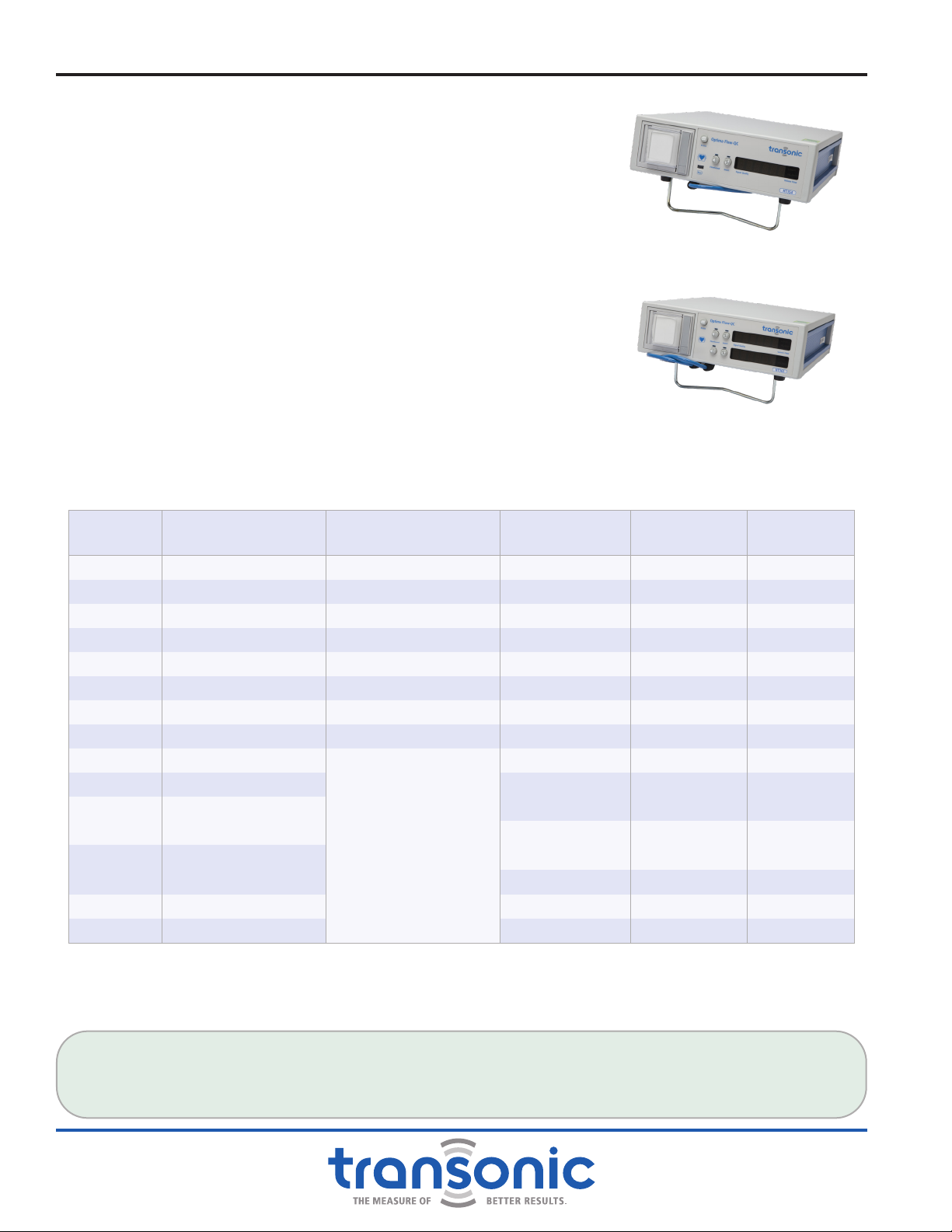
E. HT300 Series (-FT) Compatible Flowmeters
HT300 Series Flowmeters house electronics for processing ultrasonic
transit-time ow signals. AureFlo®works with HT300(-FT) Series
FlowTrace®Compatible Flowmeters ONLY. For AureFlo®to work with
HT300 Series Flowmeters not listed below, the Flowmeter must be
returned to Transonic®for an -FT upgrade (IX. Equipment Return
Instructions, page 34). All HT35x/HT36x Series Flowmeters are
FlowTrace®compatible without requiring an upgrade.
The table below lists all HT300(-FT) Series FlowTrace®Compatible Flowmeters with their distinguishing
features (channels, RoHS compliance, key operated) and compatible Flowprobe/ Flowsensor Series.
MODEL # # OF CHANNELS COMPATIBLE
FLOWPROBE SERIES
FLOWPROBES #
OF USES
RoHS
COMPLIANT
KEY
ACTIVATED
HT310-FT 1HQD- 50 No No
HT312-FT 1H Q C- 8, 16 No No
HT313-FT 1HQD- 50 No No
HT314-FT 1HQD- 50 No Yes
HT320-FT 2HQD- 50 No No
HT322-FT 2H Q C- 8, 16 No No
HT323-FT 2HQD- 50 No No
HT331-FT 1HQN- 1, 16 No No
HT350 1
All HQ-Series
Perivascular Flowprobes
(HQC-, HQD-, HQE-,
HQF-, HQG- & HQN-)
1, 8, 16, 50* Yes No
HT353 1 1, 8, 16, 50* Yes No
HT353C 1 1, 8, 16, 50* Yes No
HT354 1 1, 8, 16, 50* Yes Yes
HT354C 1 1, 8, 16, 50* Yes Yes
HT360 2 1, 8, 16, 50* Yes No
HT363 2 1, 8, 16, 50* Yes No
HT364 2 1, 8, 16, 50* Yes Yes
* Number of Flowprobe uses depends on Flowprobe Series (some Probes are available in multiple versions with different number of
uses). Length of measurement period is also Probe type dependant.
Fig. 1.2: HT354 Single Channel Flowmeter
Fig. 1.3: HT363 Dual-Channel Flowmeter
Introduction
FLOWTRACE®(-FT) COMPATIBILITY
Isolated USB ports on the back panel of HT300 Series FlowTrace®Compatible Flowmeters provide a
digital output to FlowTrace®. Older Flowmeters must be upgraded by factory authorized service staff to
communicate with FlowTrace®.

AU-OPR-AureFloFT-EN,
Rev H
3
F. Perivascular Flowprobes & Clamp-on Tubing Flowsensors
Transonic®offers a wide range of intraoperative Perivascular Flowprobes and Extracorporeal Clamp-on
Tubing Flowsensors. Transonic®Flowsensors connect to a two-meter (~ 6.5 ft.) extension cable attached to
the front of the HT300 Series Compatible Flowmeter. Two or four ultrasonic transducers within the Sensor
body transmit a minimal level of ultrasound through a rectangular sensing window (Appendix E: Theory
of Operation, page 43). Volume ow of all non-aerated liquid passing through the sensing window is
measured.
1. PERIVASCULAR FLOWPROBES
Transonic®HQ-Series Intraoperative,
Perivascular Flowprobes work with HT300
Series Compatible Flowmeters to measure
instantaneous and average volume ow in
blood vessels or grafts, 0.5 mm to 36 mm in
diameter (Fig. 1.4). Perivascular Flowprobes
measure blood ow in exposed vessels:
a) at the beginning of a procedure, for accurate
assessment of volume ow.
b) at the conclusion of surgery prior to patient
closing, on newly implanted natural or
articial bypass grafts, on vessels supplying
restored, reconstructed or transplanted
organs and tissues.
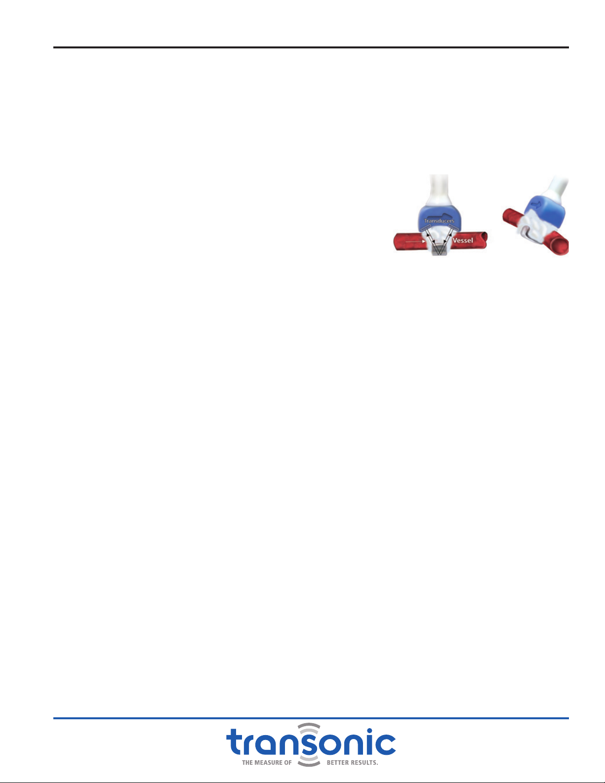
2. CLAMP-ON FLOWSENSORS
Transonic®HQ-XL-Series Clamp-on Tubing Flowsensors apply ultrasound
energy through exible tubing to monitor instantaneous and average
volume ow of blood, cardioplegia or other solutions in (Fig. 1.5):
a) Extracorporeal procedures such as cardio-pulmonary bypass (CPB);
extracorporeal membrane oxygenation (ECMO); hemodialysis;
plasmapheresis; arteriovenous hemoltration (CAVH)
b) Extracorporeal perfusion, infusion or transfusion procedures (such
as allograft perfusion for pre-transplantation preservation; coronary
reperfusion or retroperfusion; continuous total nutrient infusion,
saline or dextrose infusion; blood transfusion)
c) Extracorporeal shunts (portal vein bypass shunts, or lower body/upper
body bypass shunts during liver transplants).
Fig. 1.4: An Array of Perivascular Flowprobes
Fig. 1.5: Clamp-on Flowsensor
Introduction
4AU-OPR-AureFloFT-EN,
Rev H
II. Functions & Controls
A. Front Panel
CABLE FOR FLOWPROBE /FLOWSENSOR CONNECTION
Two meter cable attached to accept HQ-style connector of Flowprobe/Flowsensor.
DEFIBRILLATOR - PROOF TYPE CF
Cardiac-oating equipment.
FLOWSOUND®ON/OFF
Turns FlowSound®on and off. Volume control knob is located on the
rear panel.
INVERT ON/OFF
Reverses the polarity of the ow signal on the AureFlo®Monitor
screen, chart recorder, front panel LED display, rear panel analog
outputs and USB connector.
PRINT ON/OFF
Starts and stops the chart recorder.
CHART RECORDER
(Not provided on Models HT310-FT, HT320-HT, HT350 & HT360)
The chart recorder automatically scales the paper to the ow being
measured.
LED ALPHANUMERIC DISPLAY
●ULTRASOUND SIGNAL QUALITY
●MEAN VOLUME FLOW in mL or L/min and
●STATUS/ERROR MESSAGES
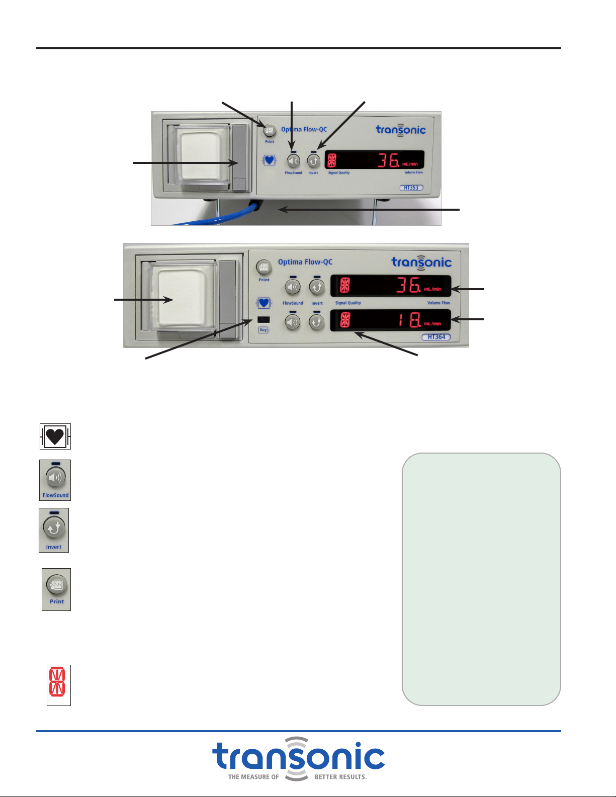
Fig. 2.1: HT353 Flowmeter Front Panel
Chart Recorder
Print On/Off
Signal Quality Indicator
Chart Recorder Door
LED
Alphanumeric
Display
FlowSound®On/Off Invert On/Off
Disposable Flow-QC®
Key Port
Cable for Flowprobe/
Flowsensor Connection
Fig. 2.2: HT364 Flowmeter Front Panel
BENEFITS OF
FLOWSOUND®
Provides audio feedback on
signal quality. The surgeon
can hear when there is good
contact while still focusing on
the surgical eld.
The surgeon has
instantaneous feedback on
changing ow conditions.
FOR EXAMPLE: A surgeon can
manipulate a kinked vessel or
graft and immediately detect
an improvement in ow.
FlowSound®warns that a key
activation period is ending
by emitting three beeps
each minute for the last ve
minutes of key activation.
AU-OPR-AureFloFT-EN,
Rev H
5
1. DISPOSABLE FLOW-QC®KEY (FLOWMETER MODELS: HT314-FT, HT354 & HT364)
HT314-FT, HT354 & HT364 Flowmeters are activated by inserting a disposable Flow-QC®Key or single
use disposable Probe. When the Meter is turned on and no Flow-QC®Key or single use Probe is
inserted, the Meter Display reads “INSERT KEY OR 1X USE PROBE”
Two Flowprobe Tests can be performed without the Flow-QC®Key inserted in the Flowmeter.
a) Flowprobe/Flowmeter Compatibility Test. When a Flowprobe is connected to the Flowmeter, the
Flowmeter displays one of two messages:
i) The Flowprobe’s ID such as “HQD3FMC”
ii) “NO PRB” or “NO PROBE” (Meter dependant)
b) Flowprobe Ultrasonic Signal Quality Test. If the Flowprobe
is coupled by immersion in saline or ultrasonic couplant and
the Flowprobe is connected to the Flowmeter, the Flowmeter
tests the transmitted ultrasound signal and displays either:
i) “GOOD SIGNAL”
ii) “LOW SIGNAL”
iii) “X NO SIGNAL” (where X equals the Probe ID).
FUNCTIONALITY OF A FLOW-QC®KEY
When a Flow-QC®Key is inserted into the Flowmeter without a Flowprobe attached, the Flowmeter
displays either (messages are Meter dependant):
i) “DISCARD KEY” or “DISCRD KEY” indicating that the key has already been used.
ii) “NO PRB” or “NO PROBE” indicating that the key is good but no Probe is connected.
FLOW-QC®KEY MEASUREMENT PERIOD
The Flow-QC®Key’s 4 hour measurement period begins when a Flowprobe is connected to the
Flowmeter and the Flowprobe’s ultrasonic window is lled with ultrasonic couplant enabling signal
transmission (Fig. 2.3). Once the Flowprobe is coupled (with saline or gel), the Flow-QC® Key’s specied
time period begins. At the end of the time, the Flow-QC®Key expires. Please note, if the Flowmeter is
unplugged during the measurement period for 20 minutes or more, the Flow-QC®Key will expire.
FLOW-QC®KEY MEASUREMENT PERIOD EXPIRATION
To warn the user that a Flow-QC®Key’s measurement period is ending, the Flowmeter generates two
types of alarms beginning ve minutes before the Flow-QC® Key’s ow measurement period is up.
i) Display Alarm as the minutes count down: “TIME LEFT 5 MIN”, “TIME LEFT 4 MIN”, “TIME LEFT 3
MIN”, “TIME LEFT 2 MIN”, “TIME LEFT 1 MIN” then “TIME IS UP”
ii) Audio Alarm during the last ve minute count down: three beeps, once each minute.
FLOW-QC®DISPOSAL
When a Flow-QC® Key’s ow measurement period is up, the Flowmeter will display “TIME IS UP.” Flow
measurement will continue to be taken until the acoustic transmission is disrupted for more than 15
seconds or the Key is removed. Once the signal is interrupted or the Key removed, ow measurement
stops and the message “DISCARD KEY” or “DISCRD KEY” is displayed. Discard the key immediately, it
can no longer be used to activate the Meter.
2. INVERT FUNCTION
Transonic® Flowprobes are bi-directional: they measure forward and reverse ow. If the ow
waveform is upsidedown, the [Invert] button can be used to ip the waveform without having to
adjust the Flowprobe. The indicator light above the button illuminates when the button is pushed and
the invert function is active. The invert function remains active until the button is pushed again or the
meter is powered off.
Fig. 2.3: Perivascular Flowprobe with
Ultrasonic Window Filled with
Ultrasonic Couplant
Functions & Controls

6AU-OPR-AureFloFT-EN,
Rev H
3. CHART RECORDER (Not provided on Models HT310-FT, HT320-FT, HT350 & HT360)
The chart recorder is used to document ow measurements, including phasic ow patterns (Fig. 2.4).
It automatically scales for the full range of ow measurements.
The chart recorder has 3 settings, selected by the rear panel Chart Recorder slide switch:
a) RUN/STOP prints continuously at 20 mm/sec; push the [Print] button to start/stop printing.
b) SLOW prints 8 seconds of ow data at 20 mm/sec: SELECT THIS MODE FOR ROUTINE OPERATION
c) FAST prints 4 seconds of ow data at 40 mm/sec.
TESTING THE CHART RECORDER: Push [Print] button. When engaged, the chart recorder prints a
header and then pauses momentarily while the paper is automatically scaled to actual ow conditions.
The chart recorder will then print a strip of ow data in real time. There is another brief pause toward
the end of the print run while ow statistics are calculated.
The print cycle can be interrupted at any time by pushing
the [Print] button a second time. Once the chart recorder
has stopped, pushing the [Print] button a third time will
initiate a new print cycle. In “RUN/STOP” Mode the chart
recorder will print continuously until the user pushes the
[Print] button a second time.
The printout is scaled to the ow conditions 8 seconds prior
to printing. Scaling cannot be modied during a print run.
Therefore, if ow increases dramatically while printing, the
measurements will go off scale. Wait until the mean values
have stabilized before attempting to print again.
CHART RECORDER END OF PROBE LIFE MESSAGE:
As the Flowprobe approaches its use limit, the following
message will be printed on the strip chart recorder:
Attention: Probe serial # xxxxxxxxxx has reached the end
of its calibration period. Please contact Transonic Systems
Customer Service @ 1-800-353-3569 to order a replacement
Flow-QC®Probe.
NOTE: Date and time on the chart recorder printout
come preset from the factory. Call Customer Service for
instructions.
LOADING THE THERMAL PAPER
1) To open door, press the bottom of
the gray bar on the recorder.
2) Remove empty paper spool.
3) Place a new spool of paper on the
paper holder so that the paper exits
the spool from the left-hand side.
4) Thread the paper through the
front panel paper deector of the
recorder.
NOTE: Installing paper with incorrect
side out will prevent proper printing.
Functions & Controls
Fig. 2.4: Chart Recorder print out
Waveform Flow Data
Flow Scale
AU-OPR-AureFloFT-EN,
Rev H
7
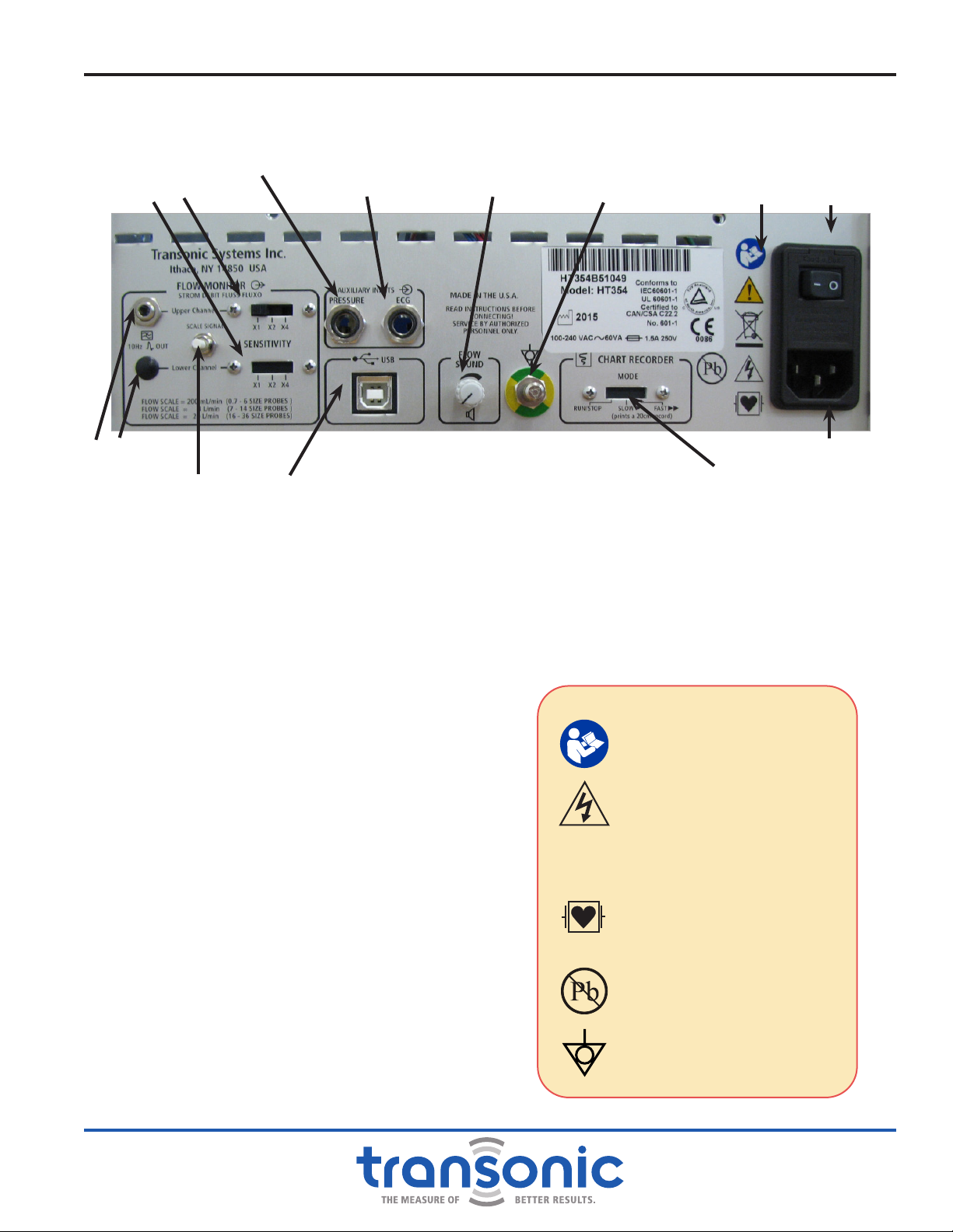
B. Back Panel
POWER ON/OFF SWITCH
To turn on power press (—) to turn off power press
(0)
ANALOG OUTPUTS
UNISCALE Output: 10 Hz low pass ltered;
Automatic gain adjustment for xed scaling of
multiple Probe sizes. Accepts 1/8"miniphono
connector.
HT31x-FT & HT35x: 1 Uniscale output
HT32x-FT & HT36x: 2 Uniscale outputs
SENSITIVITY SWITCHES
To select the Uniscale scaling for analog outputs
SCALE SIGNAL BUTTON
To set scaling of external devices connected to
Uniscale and USB outputs.
PRESSURE INPUT
1/4” Phono Jack input for pressure signal from
patient monitor.
ECG INPUT
1/4” Phono Jack input for ECG signal from patient
monitor.
USB PORT
For USB (Type B) connection to a PC-style
computer
FLOWSOUND®VOLUME CONTROL
Adjusts the volume level of the audio output.
CHART RECORDER MODE
RUN/STOP: for continuous printing at 20 mm/sec
SLOW: Prints strip at 20 mm/sec
FAST: Prints strip at 40 mm/sec
Fig. 2.5: HT35x/HT36x Flowmeter Back PanelAnalog Outputs
Sensitivity Switches
Auxiliary Analog
Input (ECG) FlowSound®Volume
Control Safety Legends Power On/Off
Switch
Power Supply Plug
Scale Signal Button Chart Recorder Mode
Switch
Ground Pin
USB Port
WARNINGS
Attention: Consult
accompanying documents
Dangerous Voltage: service
by trained technicians only
C
2797 CE Conformity Mark
Debrillator proof type CF
equipment when used with
the proper cables.
This device was manufactured
in accordance with RoHS
standards for lead content.
Equipotentiality pin:
Instrument ground
Functions & Controls
Pressure Input

8AU-OPR-AureFloFT-EN,
Rev H
1. FLOWSOUND®
FlowSound® provides an audio feedback of volume ow. It is analogous to audio Doppler, but the
sound corresponds to true volume ow, rather than to velocity. The higher the pitch, the higher the
volume ow. An octave increase in pitch corresponds to a 4-fold increase in ow. At zero ow, there is
a low hum sound. The indicator light above the button illuminates when the button is pushed and the
FlowSound®function is active. The FlowSound®function remains active until the button is pushed
again or the meter is powered off.
TO TEST FLOWSOUND® : Connect a Perivascular Flowprobe to the Flowmeter and immerse the Probe’s
head in a container of water. Turn on [FlowSound®]. The FlowSound®knob on the rear panel can
be used to adjust the sound level. Swish the Probe back and forth in the water and note the changes
in pitch as the volume of ow passing through the Probe’s ultrasonic sensing window changes.
FlowSound® is heard only when the ultrasonic signal quality is adequate for ow measurement, i.e. if
the Probe is immersed in water or applied to a vessel without air obstructions.
a) Low Pitch = ZERO or Low ow
b) Higher Pitch = Higher ow
c) No Sound = “NO Signal”: apply gel or saline inside the ultrasonic window
2. FLOWMETER OUTPUTS: CONNECT TO PATIENT MONITOR
There is one analog output on the rear panel of the Single Channel Meters and two on the Dual
Channel Meters. The voltage levels of these ow signals follow Transonic®Uniscale convention
to simplify connection to commercial intraoperative Monitors. The Uniscale is scaled according to
Flowprobe size:
PROBE DESCRIPTION PROBE SIZE SENSITIVITY AT 1X
Small Probes 0.7 - 6 size 1 Volt = 200 mL/min
Medium Probes 7 - 14 size 1 Volt = 4 L/min
Large Probes 16 - 36 size 1 Volt = 20 L/min
Therefore, when the [Flow Scale] rear panel button is momentarily depressed during normal ow
measurement:
a) Voltage on the rear panel output and USB port is switched to + 1 Volt for 10 seconds, then to 0 Volt
for 10 seconds.
b) The front panel Meter Display will simultaneously indicate the corresponding ow levels: First, the
Flowprobe’s Uniscale level of 1 Volt (200 mL/min, 4L/min or 20L/min) and then “0 mL/min” (0 Volt).
(With [Sensitivity] switch set at 1x.)
The Uniscale voltage output for a given real ow displayed on the front panel can be multiplied by a
factor of 2 or 4 by switching the [Sensitivity] switch from 1x to 2x or 4x which corresponds to 1V, 2V
and 4V respectively.
EXAMPLE OF UNISCALE SENSITIVITY
A cardiac surgeon routinely uses a 2, 3 or 4 mm Flowprobe in CABG surgery and wants to see the real-
time ow curves displayed on the central patient Monitor. Although each of these Flowprobe sizes has
a different scale factor, the Uniscale output has automatic gain adjustment, so 1 Volt = 200 mL/min, no
matter which Flowprobe size is used. If the scaling of the waveform is not appropriate, (e.g. for increased
resolution of low ows) it can be adjusted using the [Sensitivity] switch.
Functions & Controls

AU-OPR-AureFloFT-EN,
Rev H
9
III. Specications
A. FlowTrace®Software
FlowTrace®Software is designed to work with a Transonic®safety-tested and approved Transonic®model
Monitor with the following minimum specications:
●Windows XP,
Windows 7, or
Windows 8.1
●1.6 GHz processor or higher
●CD Rom drive ●1 GB of RAM
●Serial Port ●20 GB Hard Drive
●2 USB Ports ●Touch-panel display
Monitor display: 17” touch screen
B. HT300(-FT) Series Compatible Flowmeters
●Single-channel (HT31x-FT & HT35x Series), dual-channel (HT32x-FT & HT36x Series) Flowmeters
●Weight: Single Channel: 10 lb (4.5 kg); Dual Channel 11 lb (5 kg)
●Dimensions all Models: 11 3/8” (28.9 cm) wide x 4” (10.2 cm) high x 13 1/2” (34.3 cm) deep
●Attached two meter Flowprobe-to-Flowmeter extension cable per channel
●Separate grounded medical grade power line-cord is supplied with the Flowmeter.
INPUT POWER
Universal Power Supply; 50-60 Hz; 100 -240 V ± 10% (automatic voltage adjustment)
FUSES
1.5A fast blo, mfg bussman: #GMA1.5, 250 VAC (HT31x-FT & HT32x-FT Series)
1A Slow Blo, mfg. Bel: # 5HT1-R 250VAC (HT35x & HT36x Series)
Both power entry conductors are protected by size 5 x 20 mm fuses.
ELECTRICAL ISOLATION
●Cabinet is grounded; line to ground leakage current: less than 50 μA @100-120 V line; less than 100 μA @
220-240 V line.
●All electronic components and cabling of the Flowprobe/Flowsensor extension cable, Flowprobe/
Flowsensor cable and Flowprobe/Flowsensor are fully isolated from the Flowmeter’s electrical circuitry to
meet IEC60601 “cardiac oating” specications.
●Debrillator Protection: Class I “CF” IXPI device: Probes can be left attached to the patient during cardiac
debrillation for instantaneous report on the restoration of ow.
ENVIRONMENTAL
●Operating temperature range: 15ºC to 40ºC
●Operating, shipping and storage humidity: 0 to 90% RH non-condensing
●Shipping and storage temperate range: -10ºC to 50ºC
●RoHS compliant (HT35x & HT36x Series)
AUTOMATIC METER ADJUSTMENTS
●Ultrasound frequency and insonication parameters
●Flowprobe size and corresponding ow output ranges
●Volume ow calibration of connected Flowprobe
●Sampling rate optimized for local acoustic conditions

10 AU-OPR-AureFloFT-EN,
Rev H
DIGITAL FLOWPROBE/FLOWSENSOR IDENTIFICATION
Probe identication and calibration parameters are programmed on an EPROM housed inside the
Flowprobe/Flowsensor connector.
COMPATIBLE FLOWSENSORS
These Flowmeters accept a range of HQ- Series Flowprobes/Flowsensors for intraoperative surgical use. See
Probe specication sheets or your local Transonic®representative for models, sizes and recommended uses.
FLOWMETER INPUTS
Two 1/4” Phono Jack connectors are provided on the rear panel as auxiliary input for the Pressure and ECG
signal. They accept a signal range of ± 5 Volts.
USB OUTPUT PORT
Electically isolated output connector meeting IEC60601 patient isolation. For connection to the AureFlo®
Monitor. The ± 5V analog Flow signals and ECG signal are digitized at 100 Hz sampling rate with 12-bit
resolution. Data is supplied at 19200 Baud with 8 data bits, 1 stop bit, and no parity for use with FlowTrace®
software.
ULTRASONIC FREQUENCY/PARAMETERS
The ultrasound output level of the Flowprobes/Flowsensors is factory-set and does not incorporate any
interactive system features. These settings are made using “ALARA” principles (As Low As Reasonably
Achievable), and are orders of magnitude below the FDA “preamendment levels,” the USA insonication
safety limits. These settings satisfy the requirements of IEC 60601-2-37 for exemption from Mechanical
Index (MI) and Thermal Index (TI) reporting during use.
●Transducer excitation: Burst of 10 to 24 waves (probe size dependent).
●Transducer excitation frequency: 900 kHz to 9.6 MHz (probe size dependent).
●Transducer excitation rate: 900 Hz to 14 kHz (probe size dependent).
PARAMETER MEANING TRANSONIC®FLOW SENSOR
THEORETICAL MAX
IEC 60601-2-37
EXEMPTION
FROM DISPLAY
PRE-AMENDMENT
MAX (FOR CARDIAC
APPLICATIONS)
MI Mechanical Index 0.021 1 1.9
TI Thermal Index 0.91 1N/A
IMAX Maximum Peak
Intensity 2.5 W/cm2N/A 310 W/cm2
ISPTA
Spatial Peak,
Temporal Average
Intensity
45 mW/cm2N/A 430 mW/cm2
ISPPA
Spatial Peak,
Pulse Average
Intensity
2.53 W/cm2N/A 190 W/cm2
Device testing has shown that measurements are well below theoretical maximum values. Measurement uncertainties did not
exceed 30%.
REGULATORY COMPLIANCE
Transonic®Flowmeters and Flowprobes/Flowsensors comply with acceptable standards for medical and
electrical equipment (IEC60601-1). These Transonic®products are CE marked per 93/42EEC Annex II as
amended by Directive 2007/47/EEC. Transonic® is an ISO13485 certied facility.
Specications

AU-OPR-AureFloFT-EN,
Rev H
11
C. AureFlo®Cart
MECHANICAL SPECIFICATIONS
Height: 63” (160.02 cm); Width: 20” (50.8 cm); Depth: 20” (50.8 cm)
Footprint: 22” x 22”
Weight: 107 lbs. (48.6 kg)
VESA Mount: Industry standard mount for attaching a VESA Mount 2.95” x 2.95” for 12” - 22” diagonal
screen with weight range up to
30 lbs (14 kg)
LOADING CONDITIONS
●Shelf with HT300 Series mounting bracket: Flowmeter: 22 lbs maximum; Shelf load: 6 lbs maximum
●Shelf with sliding drawer: Drawer capacity 5 lbs maximum; Shelf load 15 lb maximum; 2-4 inch locking
casters
●Maximum system weight: 110 lbs.
ELECTRICAL SPECIFICATIONS
The cart provides connections to the AC power source for the HT300 Series Compatible Flowmeter, printer
and the AureFlo®Monitor. Do not plug any ancillary equipment other than that recommended in this
manual into the AureFlo’s®power outlet on its cart. Before installing any devices on the AureFlo®cart,
make sure that the system is powered off and the line cord is disconnected from the cart.
INPUT POWER
100-240VAC; 50/60Hz; 500VA Maximum
FUSES
BEL T4L: Transonic® Part #: TFSB4AM5 x 20; Mfg. part #: BEL5ST4-R
PRINTER
18VDC auxiliary power connection: The auxiliary power connection is provided to power printers that
support an 18VDC input voltage.
●Output voltage: 18VDC ± 5%
●Output current: <2.5A
Specications

12 AU-OPR-AureFloFT-EN,
Rev H
IV. Functional Tests
A. Setting Up The AureFlo®System
When you receive your AureFlo®System, all power cords will be attached to
the AureFlo®Cart’s medically isolated power source. Before turning on the
AureFlo®System these power cords must be connected to the touch-panel
PC, an HT300 Series Compatible Flowmeter and the optional printer. Use the
following steps to set up your AureFlo®System for more detailed instructions
see (Appendix A: Initial AureFlo®Setup, page 35).
1) Prior to making any connections on your AureFlo®System, make sure that
the line cord is disconnected from the AureFlo®Cart and the system is powered
“OFF”.
a) Position and attach the AureFlo®touch-panel PC to the AureFlo®Cart.
Connect one end of the USB cable to a Flowmeter (Fig. 4.1). Then
connect the opposite end to any open USB port on the bottom of the
AureFlo®touch-panel PC.
b) AureFlo®Cart’s Power Cords:
i) Connect one power cord from the AureFlo®Cart to the Universal
Power Supply port of the Flowmeter. With the AureFlo®Cart’s line
cord still disconnected, turn the Flowmeter’s power switch to “ON”
and leave it in the “ON” position.
ii) Connect the other power cord from the AureFlo®Cart to the
Universal Power Supply port of the AureFlo®touch panel PC which is
wired to turn on automatically.
c) Line Cord: connect one end of the line cord to the Universal Power
Supply port on the AureFlo®Cart. Connect the line cord to an electrically
grounded power receptacle.
2) Now turn on the AureFlo®System via the [Power On/Off] switch on the back
of the AureFlo®cart (Fig. 4.2).
3) FlowTrace®will start automatically and display on the AureFlo®Panel PC.
A FlowTrace®dialog displaying “PLUG IN A FLOWPROBE” will appear.
FlowTrace®is now ready to use.
IMPORTANT! EXIT FLOWTRACE®SOFTWARE AND POWER DOWN THE MONITOR BEFORE TURNING OFF POWER ON THE
CART. FAILURE TO PROPERLY POWER DOWN THE SYSTEM MAY CAUSE SYSTEM ERROR. FOLLOW THE DIRECTIONS IN "AFTER
MEASUREMENTS ARE COMPLETED" ON PAGE 30 FOR PROPER SHUTDOWN METHOD.
ECG / PRESSURE SIGNAL: IF PERFORMING SURGERY IN WHICH AN ECG AND/OR PRESSURE SIGNAL IS
DESIRED, CONNECT THE ECG /PRESSURE SIGNAL FOR USE WITH THE AUREFLO®SYSTEM AS FOLLOWS:
●Identify an appropriate ECG / Pressure source on the anesthesia patient monitor (with assistance from
perfusion or Biomedical Engineering, if necessary). This will be the same port as that used for the Intra-
Aortic Balloon Pump. The maximum voltage input is -5V to +5 V.
●Connect the anesthesia monitor to the AureFlo meter with the supplied cable, using the ECG or Pressure
port. Make sure both ends are connected to the same output, either 'ECG' or 'Pressure'.
●If the connection is not a 1/4" phono plug, a different cable will have to be specied and ordered
through Transonic.
●Turn on the ECG / Pressure source.
Connect to Flowmeter
Connect to Monitor
Fig. 4.1: USB Cable
Fig. 4.2: AureFlo®Cart rear pole
view with [On/Off]
switch
Flowmeter
On/Off
Cart On/Off

AU-OPR-AureFloFT-EN,
Rev H
13
Functional Tests
B. Connecting a Printer
If you have purchased a printer from Transonic Systems
Inc.®, your printer’s cord is already connected to the
AureFlo®Cart’s integrated medically isolated power
supply and the printer driver has been installed on the
AureFlo®Panel PC. The printer will always need to be
turned “ON” via the [On/Off] button on the printer if
the power to the AureFlo®Cart has been turned “OFF”.
IMPORTANT: ONLY USE A PRINTER THAT IS POWERED FROM THE
SUPPLIED, MEDICALLY ISOLATED 18 VDC CONNECTOR.
For a printer not purchased from Transonic®:
1) Verify the connection of the supplied USB cable
to the appropriate port on the rear of the printer.
Verify the connection of the opposite end of the USB
cable to an available port on the Panel PC.
2) Connect the loose end of the printer’s power cord
& adaptor cable to the power port on the rear of
the printer. Power “ON” the printer via the printer’s
[On/Off] button. Note: Depending on the printer a
different adaptor cable may be required.
Printing options are controlled from the dialog box that opens after selecting [Print] (Fig. 4.3).
C. Testing The AureFlo®System
The following tests acquaint the user with operation of the AureFlo® System:
1) Turn on AureFlo®System per instructions above. If the system is on but FlowTrace®is not open, double
click the FlowTrace®icon on the desktop of the Monitor. During FlowTrace®startup the AureFlo®
Monitor will display a start-up message. The Realtime screen will be displayed with the message “Plug in
Flowprobe.” This indicates that there is still no Flowprobe/Flowsensor connected to the Flowmeter.
2) From the [System Settings] menu, use the [FlowTrace®Settings] dialog on the AureFlo®Monitor
to enter the institutions’s name for display on printouts only. Enter all Surgeon's names for inclusion in
patient information. The default surgery is the last surgery selected and all FlowTrace®Settings default
to last selected (Fig. 7.1, page 28). If nothing has previously been selected the default surgery is CABG
and all FlowTrace®settings are selected as active.
3) Use the [Patient Settings] menu to update patient name and information. Update surgery type if
necessary.
4) Use the self-aligning push-lock connector to connect a Flowprobe or Flowsensor to the Probe extension
cable at the front of the Flowmeter. Make sure that the connector is fully pushed in. The AureFlo®
Monitor’s display will show “NO SIGNAL” at the top center of the new screen (Fig. 4.4, page 14).
The ve black bars on the right-hand side of Fig. 4.4 indicates that there is no ultrasonic transmission
reaching the Flowprobe because there is no acoustic coupling. See Fig. 4.5 on page 15 for signal
indicator bar strength explanation.
Fig. 4.3: Print options dialog box. Printer drop-down menu is
only available if multiple printers are installed on the
AureFlo®system.

14 AU-OPR-AureFloFT-EN,
Rev H
D. Testing The Flowprobes
NOTE: Flow-QC®keys are not required to test signal quality. Single use Probes should only be tested shortly
before use as the signal test will begin the measurement period.
1) Immerse the Flowprobe in a container lled with sterile saline to establish ultrasonic coupling.
2) Dislodge any air bubbles from the Flowprobe’s surfaces. Gently move the Flowprobe back and forth in
the saline to remove all air bubbles.
3) Observe the Signal Indicator Display on Realtime mode (Fig. 4.4). The bars will change from black to red
to yellow to green as the strength of the signal increases and acoustic transmission is established (Fig.
4.5, page 15).
4) When a Flowprobe is connected and there is adequate ultrasonic transmission, ow can be measured.
This is indicated by a waveform on the scrolling bar of the touch-panel display.
Functional Tests
FLOWPROBE/FLOWSENSOR QUALITY TEST
Three yellow bars indicate an adequate signal strength for ow measurements with Flowprobes/
Flowsensors. However, ultrasound signal attenuation will be higher on blood vessels during surgery.
Therefore, the Flowprobe/Flowsensor quality acceptance level during saline testing should be at least four
green bars.
Fig. 4.4: FlowTrace®screen in Realtime mode. The “NO SIGNAL” message at top of the screen and signal
indicator lights on the touch-panel display’s right side indicate that the Flowprobe is not receiving
ultrasonic transmission.
NO SIGNAL!
ECG Signal
This manual suits for next models
16
Table of contents
Other Transonic Industrial Equipment manuals

Popular Industrial Equipment manuals by other brands

ABB
ABB HT564258 Operation manual

SEW-Eurodrive
SEW-Eurodrive MOVIGEAR MGF-DBC Series operating instructions

Matsing
Matsing MS-MBA-4.4-SH2-SH2 instruction manual

ABB
ABB THF Series Installation and operation instruction

Graco
Graco Power-Lock Instructions - parts

NOZAG
NOZAG NSE S Series Assembly and operating manual


