Transonic 400 Series User manual
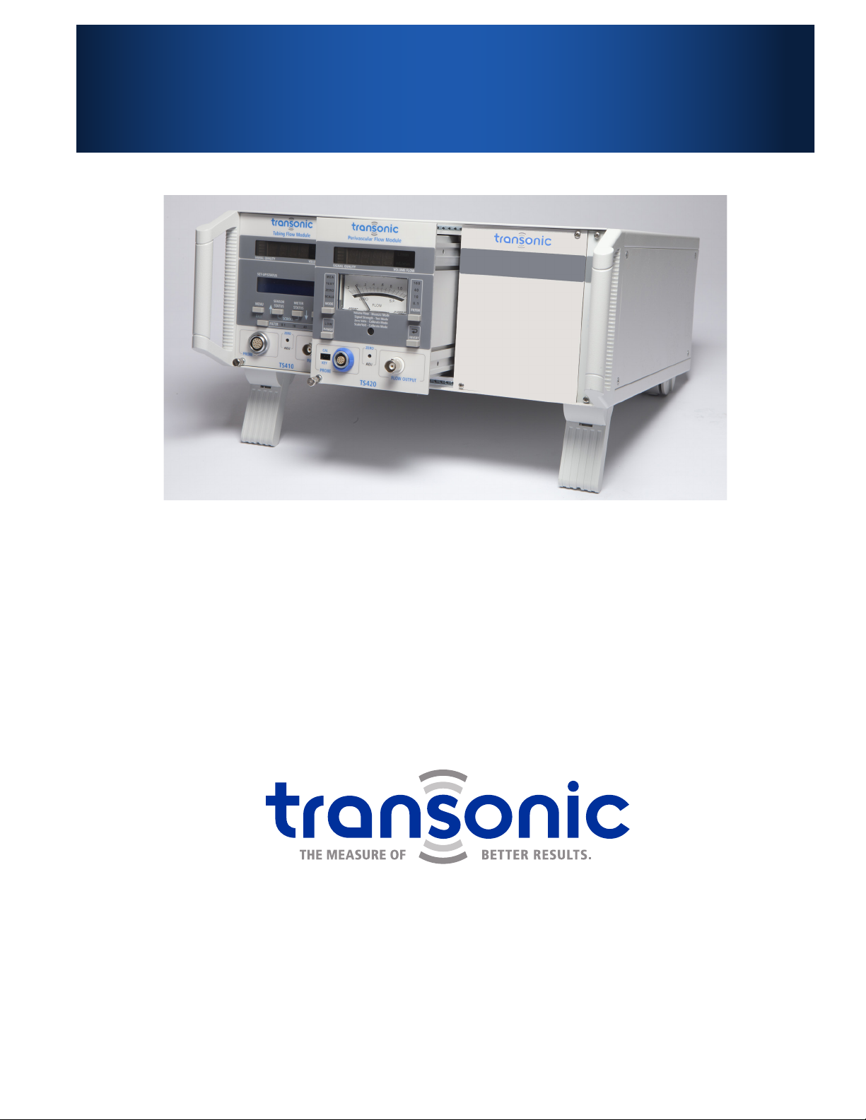
Transonic®400-Series Consoles &
Modules For Research Use
Models:
Consoles: T402, T403
Modules: TS410, TS420 & SP430
AU-OPR-400Ser-EN, Rev D Last Updated 12/22/17
OPERATOR’S MANUAL
P
M
C
AMERICAS
Transonic Systems Inc.
34 Dutch Mill Rd
Ithaca, NY 14850
U.S.A.
Tel: +1 607-257-5300
Fax: +1 607-257-7256
support@transonic.com
EUROPE
Transonic Europe B.V.
Business Park Stein 205
6181 MB Elsloo
The Netherlands
Tel: +31 43-407-7200
Fax: +31 43-407-7201
europe@transonic.com
ASIA/PACIFIC
Transonic Asia Inc.
6F-3 No 5 Hangsiang Rd
Dayuan, Taoyuan County
33747 Taiwan, R.O.C.
Tel: +886 3399-5806
Fax: +886 3399-5805
support@transonicasia.com
JAPAN
Nipro-Transonic Japan Inc.
7th Floor, Maruha Building
11-1Matsuba-cho
Tokorozawa City, Saitama
359-0044 Japan
Tel: +81 04-2946-8541
Fax: +81 04-2946-8542
japan@transonic.com

ii AU-OPR-400Ser-EN,
Rev D
Table of Contents
Table of Contents.....................................................................................................................................................................ii
Warnings & Precautions .........................................................................................................................................................iv
I. Introduction.......................................................................................................................................................................1
II. T402 & T403 Multi-channel Consoles................................................................................................................................2
A. T402 Multi-Channel Bench-top Console ..................................................................................................................................... 2
B. T403 Multi-Channel Bench-top Console..................................................................................................................................... 2
C. Console Care............................................................................................................................................................................. 2
i. CONSOLES: FUNCTIONS & CONTROLS .......................................................................................................................................... 3
ii. CONSOLES: SPECIFICATIONS ......................................................................................................................................................... 4
iii. CONSOLES: DIRECTIONS FOR USE................................................................................................................................................. 5
A. Installing Modules ..................................................................................................................................................................... 5
B. Removing Modules.................................................................................................................................................................... 5
C. Synchronization ......................................................................................................................................................................... 5
1. Self-Triggering....................................................................................................................................................................... 5
2. Sequential Triggering ............................................................................................................................................................ 6
III. TS410 Tubing Flow Module ...............................................................................................................................................7
A. Compatible Flowsensors ............................................................................................................................................................ 7
i. TS410 MODULE: FUNCTIONS & CONTROLS................................................................................................................................... 8
A. Modes of Operation................................................................................................................................................................... 9
B. Filter Settings ............................................................................................................................................................................ 9
C. Analog Outputs......................................................................................................................................................................... 9
ii. TS410 MODULE: SPECIFICATIONS ............................................................................................................................................... 10
iii. TS410 MODULE: FUNCTIONAL TESTS.......................................................................................................................................... 11
A. Flow Module Set-up ................................................................................................................................................................ 11
B. Flowsensor Zero Offset............................................................................................................................................................ 11
C. User Adjusted Gain.................................................................................................................................................................. 12
D. Calibrating a Data Acquisition System ...................................................................................................................................... 12
iv. TS410 MODULE: DIRECTIONS FOR USE ....................................................................................................................................... 13
A. Program Menu ........................................................................................................................................................................ 13
B. Alarms Menu........................................................................................................................................................................... 14
C. Use of Clamp-on Flowsensors.................................................................................................................................................. 14
D. Use of Inline Flowsensors......................................................................................................................................................... 16
IV. TS420 Perivascular Flow Module.................................................................................................................................... 17
A. Compatible Flowprobes ........................................................................................................................................................... 17
i. TS420 MODULE: FUNCTIONS & CONTROLS ................................................................................................................................ 18
A. Modes of Operation................................................................................................................................................................. 19
B. Filter Settings .......................................................................................................................................................................... 19
C. Analog Outputs....................................................................................................................................................................... 19
D. Calibration (Cal) Keys............................................................................................................................................................... 19
ii. TS420 MODULE: SPECIFICATIONS ............................................................................................................................................... 20

AU-OPR-400Ser-EN,
Rev D
iii
All contents of this document Copyright © 2017 Transonic Systems Inc.®All Rights Reserved.
The following are Registered, U.S. Patent and Trademark Ofce: COndence Flowprobe®, EndoGear®,
Endosomatic®, PhysioGear®, PhysioView®, Transonic®, Transonic Systems Inc.®
Table of Contents
iii. TS420 MODULE: FUNCTIONAL TESTS.......................................................................................................................................... 21
A. Flow Module Set-up ................................................................................................................................................................ 21
B. Perivascular Flowprobe Signal Quality Test............................................................................................................................... 21
C. Flowprobe Zero Offset............................................................................................................................................................. 22
D. Determining Scale Setting........................................................................................................................................................ 22
E. Calibrating a Data Acquisition System ...................................................................................................................................... 22
iv. TS420 MODULE: DIRECTIONS FOR USE....................................................................................................................................... 23
V. SP430 Pressure Amp Module ..........................................................................................................................................25
A. Compatible Pressure Catheters and Transducers....................................................................................................................... 25
1. Transonic Scisense Pressure catheters.................................................................................................................................. 25
2. Transpac®IV Pressure Transducer (Transonic®part # YS100)............................................................................................... 25
i. SP430 MODULE: FUNCTIONS & CONTROLS ................................................................................................................................ 26
A. Front Panel.............................................................................................................................................................................. 26
B. Modes of Operation................................................................................................................................................................. 27
C. Analog Outputs....................................................................................................................................................................... 27
ii. SP430 MODULE: SPECIFICATIONS ............................................................................................................................................... 28
iii. SP430 MODULE: FUNCTIONAL TESTS.......................................................................................................................................... 29
A. Transducer Calibration Check................................................................................................................................................... 29
B. Calibrating a Data Acquisition System ...................................................................................................................................... 29
iv. SP430 MODULE: DIRECTIONS FOR USE....................................................................................................................................... 30
A. Transonic Scisense Pressure Catheters...................................................................................................................................... 30
B. Dual Pressure Catheters........................................................................................................................................................... 30
C. Catheter Cleaning & Care ........................................................................................................................................................ 30
D. Transpac®IV Pressure Transducers........................................................................................................................................... 31
VI. Guarantee, Service and Warranty...................................................................................................................................32
A. Limited Warranty..................................................................................................................................................................... 32
VII. Equipment Return Instructions .......................................................................................................................................33
A. Consoles & Modules................................................................................................................................................................ 33
B. Flowprobes, Flowsensors & Transonic Scisense Pressure Catheters ........................................................................................... 33
Appendix A: Theory of Operation .........................................................................................................................................34
Appendix B: EMC Tables ........................................................................................................................................................35
Appendix C: Symbols & Signs ................................................................................................................................................36

iv AU-OPR-400Ser-EN,
Rev D
Warnings & Precautions
√Read this manual before use. Failure to follow the instructions and the Warnings and Precautions below
may result in risk of re or electric shock.
√Research Consoles & Modules
●Transonic® Research Consoles and Modules, and compatible Probes, Sensors, Transducers and Catheters
are designed only for investigative use with animals and are not for use in humans. Contact Transonic
Systems Inc.®for alternative products for human use applications.
●Safe and effective use of the Transonic® Console with Flow Module(s) and/or Pressure Amplier
Module(s) depends on correct application technique, adequate precaution and readiness for
emergencies. Prevent liquids and vapors from entering the device.
●The instrument Console and/or Modules are fragile electric equipment. They must be transported and
stored at temperatures between -20ºC to +60ºC with humidity between 0 - 90% RH non-condensing.
Rated altitude: 2000 meters. Operational temperatures must be between 0°C to +40°C with humidity
between 20 - 90% RH non-condensing.
√Perivascular Flowprobes
●Transonic® Perivascular Flowprobes are designed for acute use and/or chronic implantation in animals.
Excessive vessel manipulation or constrictive Flowprobe t may cause vessel spasm or damage and thus
should be avoided.
●Recalibration of the Flowprobe is necessary if the Flowprobe is to be used at a different temperature or
on a liquid other than the one for which it was calibrated.
√Tubing Flowsensors
●Transonic® Flowsensors are designed for laboratory use only.
●Transonic® Tubing Flowsensors are designed for measuring non-aerated liquid ow in tubing and should
not be applied to blood vessels or other internal ducts. They should be used only on tubings and for
liquids for which they were calibrated.
●Tubing Flowsensors are not designed to measure non-liquid (gaseous) uid ow.
●Clamp-on Flowsensors are not designed to measure liquid ow in metal or hard plastic pipes. Clamp-on
Flowsensors should not be immersed in liquids for extended periods of time.
●Factory or on-site recalibration of Tubing Flowsensors is necessary if the Flowsensor is to be used on a
different tubing, liquid or temperature other than for which it was calibrated.
√Pressure Transducers
●Pressure Transducers compatible for use with the SP430 Transonic Scisense Pressure Amplier Module
must be used according to manufacturers’ instructions and are only intended for use with animals or
in laboratory models when connected to a SP430 Pressure Amplier Module in a 400-Series Console,
regardless of individual Pressure Transducer classication.
●Transonic Scisense Pressure Catheters contain metal and are not compatible with MRI.
√Safe Electrical Use
●Use only with grounded power receptacle to reduce risk of shock.
●Position instrument so that rear panel switch and plug are accessible for quick disconnect.
●Install only Transonic®manufactured Modules in 400-Series Consoles. Do not use with alternative power
supplies.
●Do not turn on Console unless Modules are installed and panel covers are in place for empty bays.
●Do not remove or replace Modules in the Console with power turned on.
●Keep ammable liquids and vapors away from the Console and Modules. They may cause a re in the
instrument.
●All repair on Consoles or Modules must be performed by qualied electrical technicians authorized by
Transonic Systems Inc.®
√For a list of possible warning symbols please refer to “Appendix C: Symbols & Signs”
AU-OPR-400Ser-EN,
Rev D
1
I. Introduction
NOTE: In this manual, “Consoles” refer to T402 & T403 Multi-channel Consoles.
NOTE: “Modules” refer to the TS420 Perivascular Flow Modules, TS410 Tubing Flow Modules & SP430
Transonic Scisense Pressure Amplier Modules.
NOTE: In this manual, “Probe” and “Flowprobe” refer to Transonic® Precision Perivascular Flowprobes.
NOTE: “Sensor” and “Flowsensor” refer to Transonic® Clamp-on and Inline Tubing Flowsensors.
NOTE: “Transducers” refer to Pressure Transducers including Transonic Scisense Pressure Catheters and/or
Transpac® IV Pressure Transducers. “Catheters” refer to Transonic Scisense Pressure Catheters.
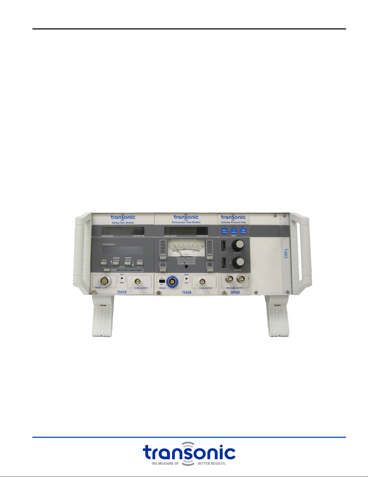
Mix and match the measurement capabilities you need in a single instrumentation Console. T402 and T403
line cord powered Consoles are multi-channel capacity cases with a shared universal power supply and
back-panel analog outputs compatible with most data acquisition systems. The T402 and T403 Consoles
accept any 400-Series Modules:
●TS420 Perivascular Flow Module: for in vivo arterial/ venous blood ow
●TS410 Tubing Flow Module: for volume ow of uid in tubing
●SP430 Transonic Scisense Pressure Amplier Module: for arterial/venous blood pressure
BOTH A CONSOLE AND A MODULE ARE REQUIRED TO TAKE MEASUREMENTS.
Fig. 1.1: T403 Console with TS410 Tubing Flow Module, TS420 Perivascular Flow Module
and SP430 Transonic Scisense Pressure Amp
2AU-OPR-400Ser-EN,
Rev D
II. T402 & T403 Multi-channel Consoles
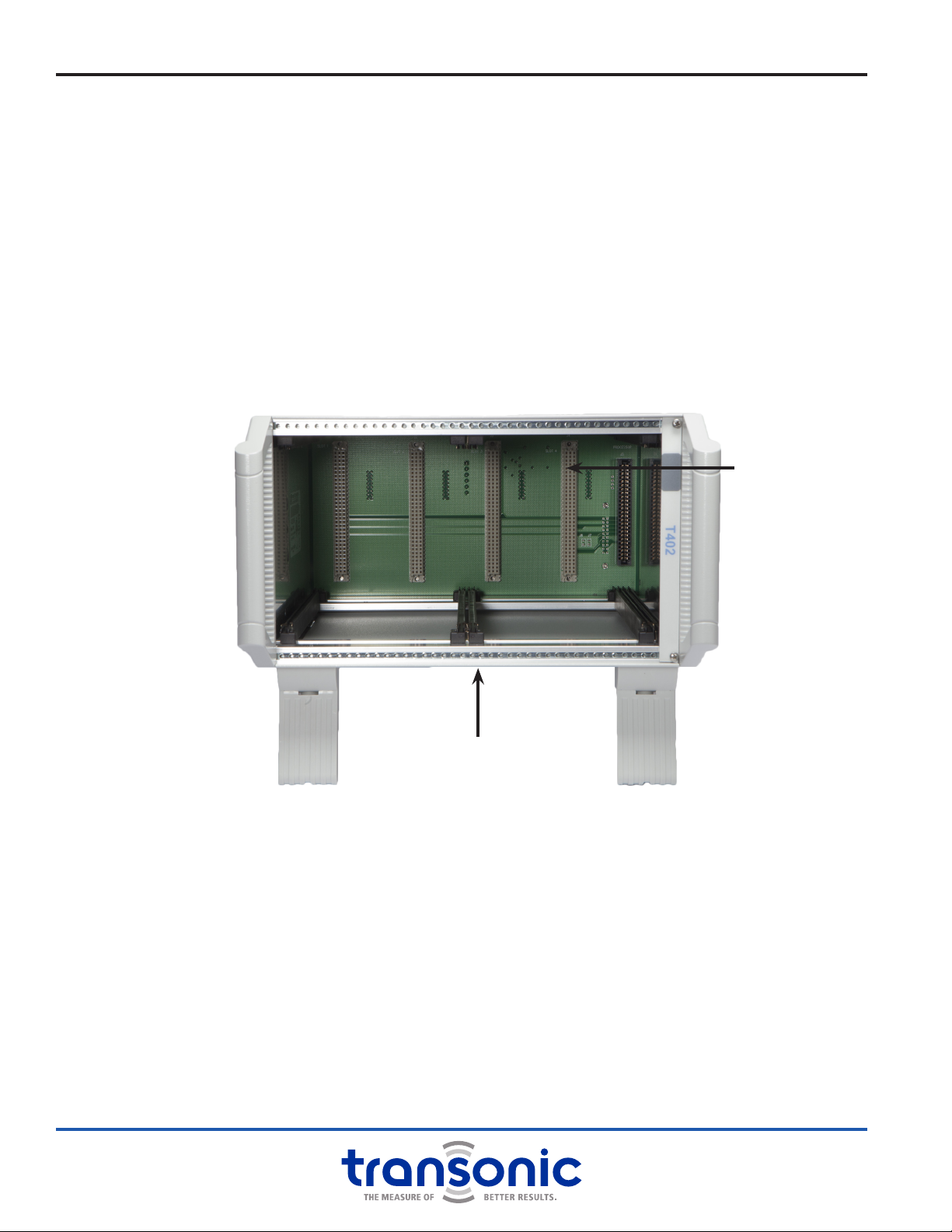
Fig. 2.1: T402 Console without any Modules
All 400-Series Consoles are line powered with convenient carrying handles and tiltable front feet. Consoles
are not stand alone pieces of equipment; a properly connected, compatible Module is required to make
measurements.
A. T402 Multi-Channel Bench-top Console
Four-Bay Console
Holds up to two double-bay wide Modules, one double-bay Module and two single-bay Modules or a
combination.
B. T403 Multi-Channel Bench-top Console
Six-Bay Console
Holds up to three double-bay wide Modules, two double-bay Modules and two single-bay Modules or a
combination.
96-pin DIN connector
Module mounting rails
C. Console Care
It is recommended to keep all Console bays covered during use and storage. Those bays which are not lled
by a Module may be covered with a blank panel cover (available in both single and double width). This will
help keep dust and particulates out of the Console.
Turn the power off before cleaning the Console. Exterior surfaces can be cleaned using a cloth or brush
dampened with soapy water, followed by damp wiping with clear water. For disinfection, the surface can
be damp-wiped with 70% isopropyl alcohol. Do not drip or splash liquids into the Console.
Modules and Consoles exposed to accidental spillage should be unplugged immediately from the power
source. Remove the Module(s). If the spilled uid is potentially corrosive or may leave a residue, carefully
wipe the area of the spill in the Console and the outside of the Module cabinets with a damp cloth
taking care not to ood the internal electronic boards. Compressed air may be used to blow liquid off
components, repeating the rinse and air-blowing as needed.
DO NOT OPERATE THE CONSOLE IN A WET CONDITION; KEEP IT IN A DRY ENVIRONMENT.
AU-OPR-400Ser-EN,
Rev D
3
i. Consoles: Functions & Controls
B. Back Panel
POWER ON/OFF SWITCH
Switch power On & Off for the Console and all connected Modules
FUSES
Two user replaceable fuses are located under a protective cover
SCREW TERMINAL BLOCK ANALOG OUTPUTS
12-screw terminal blocks. Outputs dependent on connected
Module. Use general purpose stranded hookup wire to connect
terminals with a data acquisition system.
NOTE: Double-bay wide Modules only use odd numbered slots.
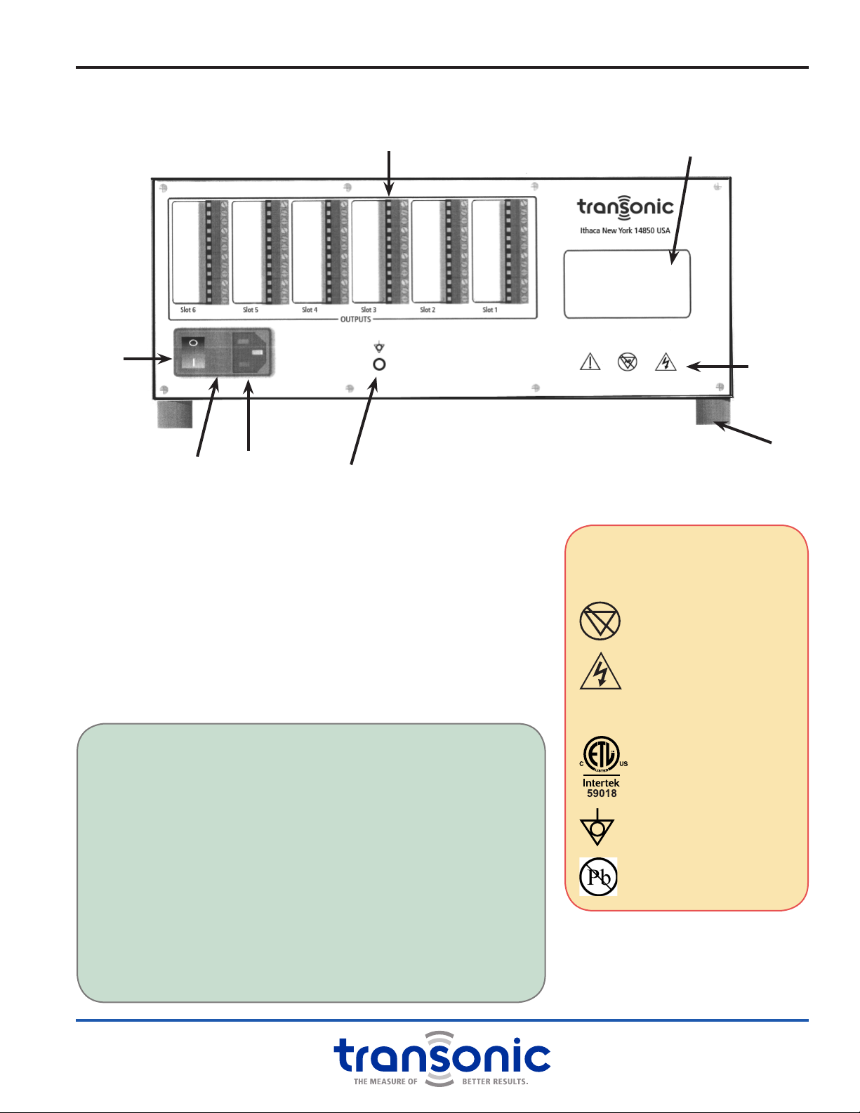
Fig. 2.2: T403 Back Panel
Serial Number and Product
Information Location
Screw Terminal Block Analog Outputs
Power
On/Off
Switch
Fuse
Location Universal
Power Supply Ground Pin
Foot
Legend
WARNINGS/ LABELS
YAttention: Consult
accompanying documents
AP Not category AP equipment
Dangerous Voltage: Service by
trained technicians only
CCE Conformity Mark
ETL Testing Mark: Electrical
Safety Compliance Certication
Equipotentiality pin: Instrument
ground
RoHS Compliant
CHANGING FUSES
The Universal Power Supply is protected from power surges by
two replaceable fuses. These are located on the rear panel of the
Console. Should the Console fail to power on, the fuses may need
to be replaced.
●With the power cord unplugged, gently pry open the tab side of
the black plastic frame to the left of the power switch with a at
screwdriver.
●The cover will open exposing two tabs with arrows. Lift up under
the arrow tabs and pull out the fuse holder.
●If the fuses are blown, replace with 0.8 Amp fast blo fuses
(Bussman # GMA0.8, 250 VAC).
●If the Console still does not power on, contact your local
Transonic®representative.

4AU-OPR-400Ser-EN,
Rev D
iii. Consoles: Specications
WEIGHT/ SIZE
T402 Four Bay Console
●5.21” h x 9.25” w x 12” d
●5.8 lbs
T403 Six Bay Console
●5.21” h x 13.46” w x 12” d
●7.6 lbs
Consoles have side panel handles and tiltable front feet for easy viewing
MODULE COMPATIBILITY
Accepts 400-Series Flow and Pressure Amplier Modules
ELECTRICAL
Console is grounded. If accidentally left ungrounded, line to isolation ground leakage current is less than
50 microamperes.
RoHS COMPLIANT
POWER
AC Input: 100-240 VAC; 50-60 Hz, 50 watts
Fuses: 0.8A fast blo, mfg bussman # GMA0.8, 250 VAC
POWER CORD
USA/Japan: Feller 458-H161 or equivalent
Europe: Feller 199-000 or equivalent
United Kingdom: Feller 209-000 or equivalent
Australia: Feller 198-000 or equivalent
AUDIBLE ALARM
Beeping alarm, non-adjustable volume. Trip level and on/off setting activated through TS410 program.
MODULE CAPACITY
●T402 Four Bay Console: Accepts 2 double-bay, wide Modules of 20 HP width or 4 single bay, narrow
Modules of 10 HP width or a combination of wide and narrow Modules.
●T403 Six Bay Console: Accepts 3 double-bay, wide Modules of 20 HP width or 6 single bay, narrow
Modules of 10 HP width or a combination of wide and narrow Modules.
CONSOLE TO MODULE CONNECTION
96-pin DIN connector on proprietary backplane. Thumb-screw to lock into front panel.
SIGNAL OUTPUTS
Back panel screw terminal block receives output signals from Module(s) via DIN 96-pin connection with
Console; 12 output connections per Module, two dedicated for ground; See Module specications for
signal denition and voltage rating. Use with general purpose hookup wire; stranded wire is preferred.
●Wire: UL 1007 or equivalent; 24 - 14 gauge
●Minimum strip length: 6 mm (0.236 inches)
AU-OPR-400Ser-EN,
Rev D
5
iv. Consoles: Directions For Use
A. Installing Modules
INSTALL ONLY MODULES THAT ARE COMPATIBLE WITH TRANSONIC’S 400-SERIES CONSOLES.
●Be sure the power on the Console is turned off.
●Align wide Flow Modules (TS410 & TS420) with right and left upper and lower rails.
●Align narrow Modules (SP430 Pressure Amplier Modules) on either left or right set of upper and lower
rails.
ALWAYS PLACE SP430 MODULES IN ONE OF THE BAYS (SLOT 3, 4, 5 OR 6)
ON THE RIGHT SIDE OF THE CONSOLE TO ENSURE BEST SIGNAL QUALITY.*
●Slide Module into the Console and push gently on upper and lower portion of the front panel to engage
the rear panel 96-pin connector. The Module will click into place so that the Module is slightly recessed in
the Console.
●Lock into place by tightening the thumbscrew.
●Cover any empty Module slots with a blank panel cover from Transonic®. Align the cover holes with the
console top and bottom horizontal rails and screw into place.
B. Removing Modules
Modules may be removed for transfer to another compatible Transonic® Console or for repair by a qualied
electrical technician authorized by Transonic®.
●Turn power off on the back of the Console.
●Loosen the thumbscrew in the lower left corner of the Module until it is un-threaded and free from the
Console, but not removed from the Module.
●Pull gently on the screw and BNC connector to disengage the rear panel 96-pin connector.
●Slide the Module out of the Console.
●It is recommended to cover any vacant Console bays with a blank panel cover to protect the Console.
C. Synchronization
The timing of ultrasonic signal bursts for Transonic® Flow Modules and other ultrasonic devices in the
same frequency range should be synchronized to avoid interference between multiple Probes/Sensors
that are within a 20 cm area. Cross-talk between Probe/Sensor signals causes unpredictable errors in ow
measurement such as increases in zero offset and corrupt ow waveforms. No external synchronization is
required for the SP430 Pressure Module.
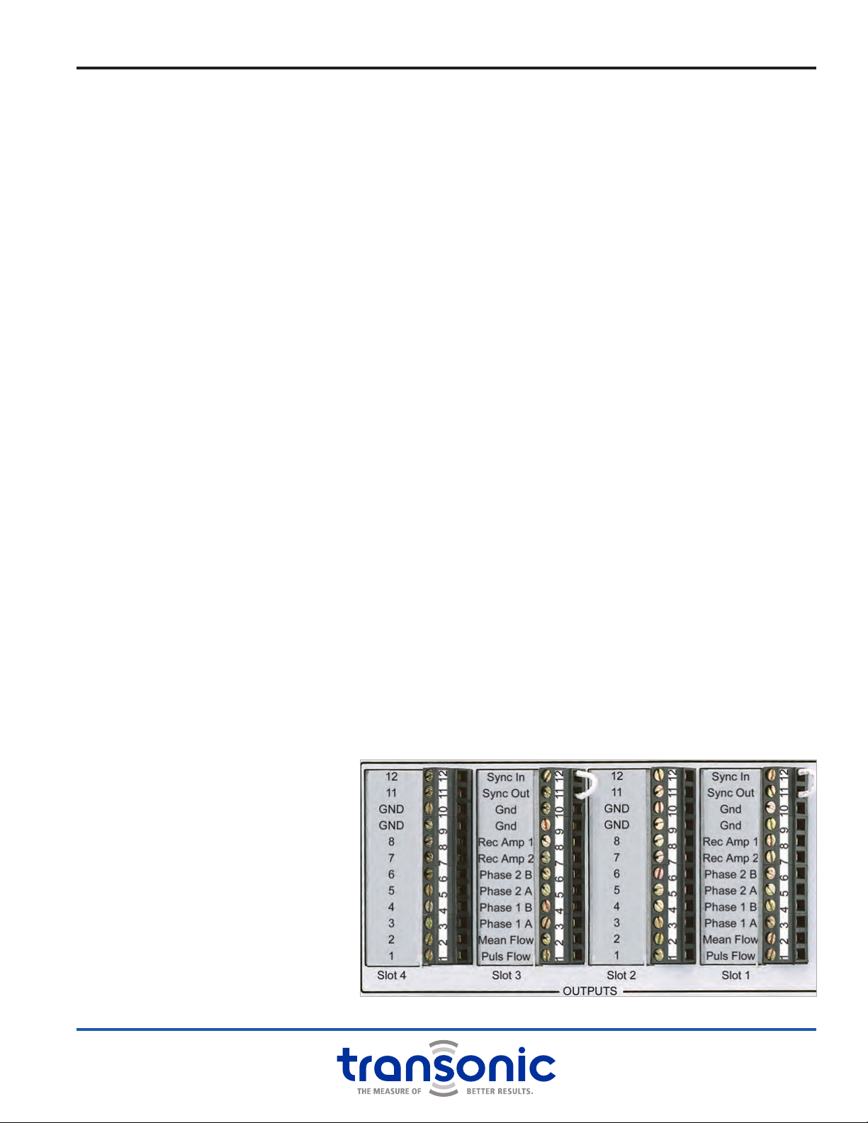
1. SELF-TRIGGERING
Connect Terminal block pin 11
“Synch Out” to pin 12 “Synch
In” via jumper on same terminal
block. This gives the lowest ow
noise and is selected when a
Flow Module runs by itself, or
multiple Flowprobes/Flowsensors
on multiple Modules run
simultaneously with sufcient
distance (>20 cm) between
Probes/Sensors. NOTE: Flow
Modules are shipped from the
factory in self-trigger mode
unless otherwise specied. Fig. 2.3: Self-triggering Synchronization
6AU-OPR-400Ser-EN,
Rev D
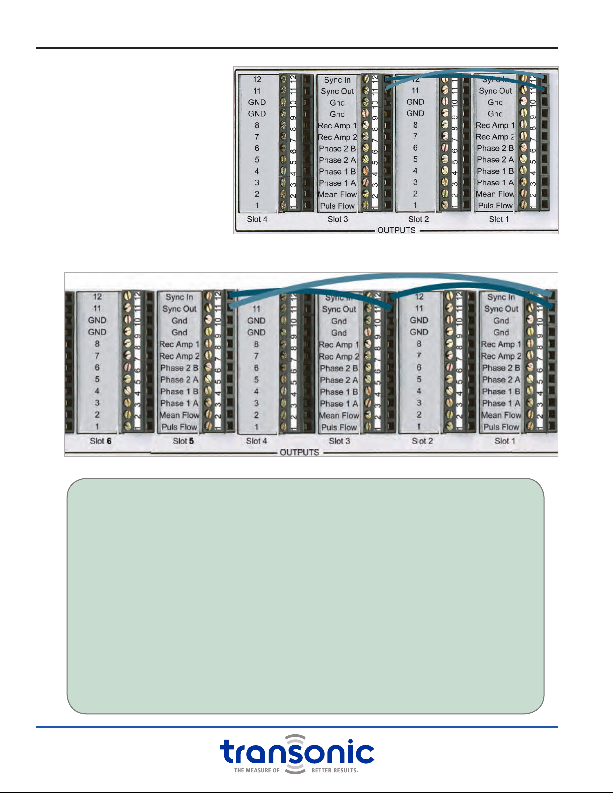
2. SEQUENTIAL TRIGGERING
Interconnect 2 or 3 Flow
Modules on the rear panel with
jumpers between Modules (pins
11 & 12) from “Synch Out” to
“Synch In” as shown (Fig. 2.4)
& (Fig. 2.5). This wiring avoids
the ow offsets that could
result from ultrasonic cross-
talk between adjacent Probes/
Sensors. NOTE: Be careful to
choose the active terminal
connections that correspond to
the installed Modules (TS410 & TS420
use the odd numbered terminal slots).
Fig. 2.4: Sequential Triggering with 2 Flow Modules
Fig. 2.5: Sequential Triggering with 3 Flow Modules
Consoles: Directions For Use
TEST FOR CROSS TALK
(To determine if Modules require sequential triggering)
• Place Flowprobes on vessels or Flowsensors on tubing as they will be used (when < 20 cm apart).
• Record both average and pulsatile ow from each Probe/Sensor simultaneously.
• Disconnect Probe/Sensor-1 from the Module connector leaving Probe/Sensor-2 in place.
• Observe any changes in average ow value or waveform of Probe/Sensor-2.
• Reconnect Probe/Sensor-1 and continue recording from both Probes/Sensors.
• Disconnect Probe/Sensor-2 from the Module leaving both Probes/Sensors in place.
• Observe any changes in Probe/Sensor-1 average ow value or waveform recording.
• If the following conditions occur, sequential-triggering for the Flow Modules is recommended:
• Shift in average ow baseline when 2 Probes/Sensors are used together compared with each
Probe/Sensor used separately.
• Erratic ow wave pulses or shifts in baseline when both Probes/Sensors are used together.
• Unnatural spikes in the waveform.
• Repeat test after sequential jumpers are in place to conrm synchronization (correction of
previously determined issue).
AU-OPR-400Ser-EN,
Rev D
7
III. TS410 Tubing Flow Module
The TS410 Tubing Flow Module measures a single channel of volume ow using ultrasonic transit-time
technology. The Module operates both Inline and Clamp-on Flowsensors for measuring volume ow in
exible plastic tubing circuits. The Flowsensors can be calibrated for and used with most non-aerated
liquids including but not limited to: blood, saline, water, cell culture, physiological buffers, and blood
analogs such as glycerine/water solutions.
The TS410 Module allows the user
to select precongured calibration
options, change the gain to
recalibrate the Flowsensor on-site,
and set parameters and alarms.
Acoustical velocity phase signals are
also available for ultrasound dilution
measurements.
The TS410 Tubing Flow Module must
be properly installed in a compatible
400-Series Console to function.
See”Installing Modules” on page 5
for installation instructions.
A. Compatible Flowsensors
See Tubing Flowsensor yer (RL-28-y) for more detailed specications.
ME-PXL CLAMP-ON TUBING FLOWSENSORS
Easy to operate, clip-on ME-PXL Flowsensors allow for sterility to be maintained in the ow system by
attaching to the outside of the tubing while measuring ow within (Fig. 3.2). Sensors are sized by OD in
1/16” increments for tubing between 1/8” and 1-1/4” OD. Metric sizes are also available for metric tubing.
PXL-Series Flowsensors can be calibrated and programmed for up to 4 different uid, temperature, tubing,
and ow rate combinations. User must specify calibration parameters at purchase.
ME-PXN INLINE TUBING FLOWSENSORS
Inline Flowsensors splice into the tubing circuit providing high sensitivity and independence from tubing
type (Fig. 3.3). Sensors are sized by ID and are available for tubing between 3/64” to 1” ID. PXN Inline
Sensors can be calibrated and pre-programmed for up to 4 uid, temperature, and ow rate combinations.
User must specify calibration parameters at purchase.
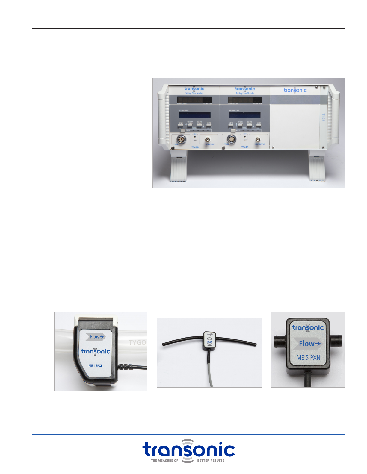
Fig. 3.1: T403 Console with two TS410 Tubing Flow Modules
Fig. 3.2: ME-PXL Clamp-on Tubing
Flowsensor on tubing.
Fig. 3.3: Small ME-PXN Inline Tubing
Flowsensor with exible
tubing ends
Fig. 3.4: Large ME-PXN Inline
Tubing Flowsensor with
rigid barbed ends
8AU-OPR-400Ser-EN,
Rev D
i. TS410 Module: Functions & Controls
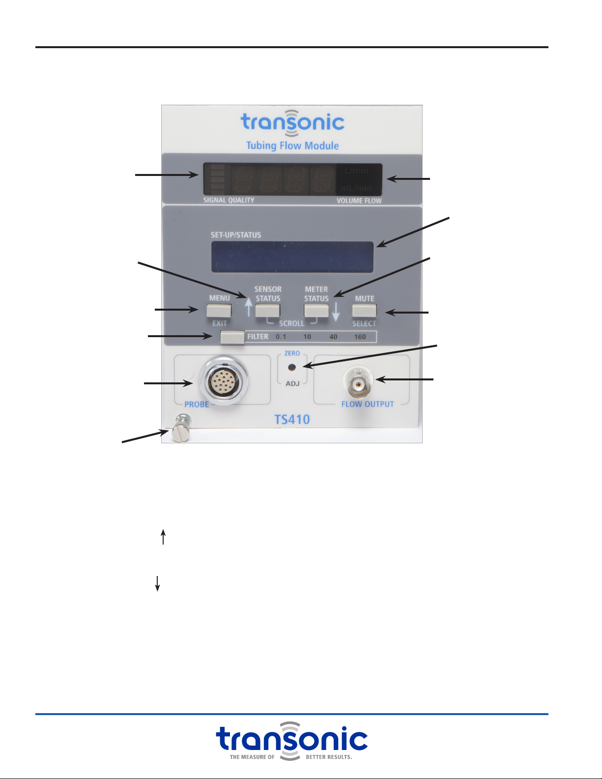
A. Front Panel
MENU/ EXIT BUTTON
Enter or exit Menu mode
SENSOR STATUS / SCROLL BUTTON
Displays Sensor calibration and gain
Scrolls up when in Menu mode
METER STATUS / SCROLL BUTTON
Display active Module settings
Scrolls down when in Menu mode
MUTE / SELECT BUTTON
Turns audible alarm on/off
Selects value or enters sub-menu in Menu mode
FILTER SELECTION BUTTON
Sets output lter to 0.1, 10, 40 or 160 Hz
ZERO ADJUST
Adjusts Module to read zero when ow is stopped
PROBE (SENSOR) CONNECTION
Connects Flowsensor or extension cable
BNC FLOW OUTPUT
BNC analog output for mean & pulsatile ow
LED DISPLAY
●Signal quality indicator
●Mean volume ow (mL/min or L/min)
LCD DISPLAY
Module and Sensor settings & Menu mode displays
LED Display
LCD Display
BNC Flow Output
Zero Adjust
Sensor Connection
Menu /
Exit Button
Sensor Status /
Scroll Button
Meter Status /
Scroll Button
Mute /
Select Button
Filter Selection Button
Attachment screw Fig. 3.5: TS410 Front Panel. Blue labels are active when in Menu
mode. White labels are active in Measure and Status modes.
Signal Quality
Indicator

AU-OPR-400Ser-EN,
Rev D
9
B. Modes of Operation
C. Filter Settings
To record instantaneous ow: set the ow
output [Filter] to a frequency at least 10
times the rate of ow pulsation. The digital
sample rate for data recording should be
set to a minimum of 3 times the application
frequency.
D. Analog Outputs
Transonic® Flow Modules output analog signals in the range of -5 volts to +5 volts that are compatible
with most A/D (analog-to-digital) converters of Data Acquisition Systems. The back panel analog outputs
generated by the TS410 Module are listed in the table below:
TS410 Module: Functions & Controls
NUMBER TERMINAL NAME VOLTAGE DESCRIPTION
12 Sync In In/Out required for operation; Multi-Module synchronization
11 Sync Out In/Out required for operation; Multi-Module synchronization
10 GND Ground
9GND Ground
8 Rec Amp 1 0 - 4 V Quality of ultrasound transmission for testing Sensor functionality, acoustic coupling
or blockage of ultrasound by air or other impedance mismatch. Can be used in bubble
detection by indicating a drop in signal as air passes through the Flowsensor. 2 V = 100%
7 Rec Amp 2 0 - 4 V Same as Rec Amp 1 for the second pair of transducers. 2 V = 100%
6 Phase 2 B ± 5 V Same as Phase 2 A but offset by +4.5 V or -4.5 V
5 Phase 2 A ± 5 V Same as Phase 1 A but for the second pair of transducers
4 Phase 1 B ± 5 V Same as Phase 1 A but offset by +4.5 V or -4.5 V
3 Phase 1 A ± 5 V Acoustic velocity of uid used in ultrasound indicator dilution studies
2Mean Flow ± 5 V Average volume ow output, ltered at 0.1 Hz
1 Puls Flow ± 5 V Instantaneous pulsatile volume ow output, ltered at 10, 40, or 160 Hz depending on the
Module front panel [Filter] setting. Output defaults to 160 Hz if 0.1 Hz button depressed.
All PXN and PXL Sensors have two pairs of transducers. Flow data is determined from the combination of both pairs while phase and
received amplitude data are separated by transducer pair.
HEART RATE OR
APPLICATION FREQUENCY
LOW PASS
FILTER
SETTING
RECOMMENDED MINIMUM
DIGITAL SAMPLE RATE FOR
DATA ACQUISITION
Average Flow Recording 0.1 Hz 0.3 Hz
Pulsatile to 60 beats/minute 10 Hz 30 Hz
Pulsatile to 240 beats/minute 40 Hz 120 Hz
Pulsatile to 960 beats/minute 160 Hz 500 Hz
MODE
OUTPUTS
LCD DISPLAY
Front Bottom
LED DISPLAY
Front Top
MEAN & PULSATILE FLOW
Front BNC/ Rear Analog
MEASURE Flowsensor model & serial number Bar indicator of signal quality
Average ow in mL/min or L/min
Start-up & error messages
Flow = recorded voltage x scale factor
Bidirectional ow output ± 5 V
SENSOR STATUS
Flowsensor calibration parameters: Fluid
type, temperature, tubing type, tubing
dimensions & % gain if adjusted
METER STATUS Module settings: Invert ow status, 1/4
scale status & active alarm values
MENU: SENSOR CONTROLS Select & change calibration & gain
MENU: METER CONTROLS
Alarm setup
1/4 ow scale Increase ow resolution Scale factor reduced by 1/4
Invert Change sign of ow Reverse signal polarity
Calibrate 0 volt scale 0 mL/min 0 V = 0 mL/min
Calibrate 1 volt scale Scale factor ow value 1 V = scale factor ow

10 AU-OPR-400Ser-EN,
Rev D
ii. TS410 Module: Specications
GENERAL FEATURES
Size: 5.125” h x 4” w x 9.062” d
Weight: 2.3 lbs.
Module ts 2 Console bays (20HP) in T402 or T403
Consoles
Power: Derives input power from 400-Series
Consoles. Installation in a Console is required.
RoHS compliant
OPERATIONAL TECHNOLOGY
Ultrasonic Transit-time
FLOWSENSOR COMPATIBILITY
ME-PXL-Series & ME-PXN-Series
SENSOR CONNECTOR
Front panel 16-pin connector. Accepts research
Inline and Clamp-on Flowsensors and extension
cables with male CC16 or CP16 connectors.
AUTOMATIC ADJUSTMENTS
Sensor size identication and corresponding ow
output ranges. Volume ow calibration and serial
number displayed of active Flowsensor.
LED DIGITAL DISPLAY
4-Digit (14 segment) LED displays Flow / Sensor
data / Error Messages
Bar Indicator Light: Displays received signal for
continuous monitoring of Sensor signal quality.
LCD DISPLAY
One line 16-character alpha numeric LCD displays
program parameters, Sensor and Module status,
alarm settings. Default displays Sensor serial
number.
SET-UP/STATUS & PROGRAM PARAMETERS
STATUS MODE: (White labels) Status message
displayed on LCD.
●Sensor Status: Sensor type & calibration
●Meter Status: Active Flow Module settings &
alarm status
●Alarm Mute: Audible alarm on/off toggle
PROGRAM MODE: (Blue labels)
●Sensor Controls: Select pre-programmed factory
calibration options; Adjust Flowsensor gain to
change calibration on-site.
●1/4 Flow Scale: Increases ow gain by factor of 4
for low ow measurements.
●Calibrate Scale: Sets output to 0 and 1 Volt to
calibrate external recording devices with scale
factor ow.
●Invert Flow: Inverts polarity of analog outputs &
ow display
●Alarms Menu: 3 level program to select, set
thresholds, and activate Alarms for “Low Flow”,
“High Flow” and “Received Signal” interruption
FILTER PROPERTIES
●0.1, 10, 40 Hz: 2nd order Butterworth, with a
third passive pole at 160 Hz
●160 Hz: 3rd order Butterworth
ZERO FLOW ADJUST
Recessed momentary push button to zero ow
reading at stopped ow.
FLOW OUTPUT
Front panel BNC output connector & rear panel
terminal block:
●Pulsatile/Average Volume Flow
●Filtering controlled by front panel selectable
lters
●Voltage range: -5 to + 5 volts
●Output resistance: 500 Ohm
●Full Range for Flow: -5 to +5 V (bidirectional
ows, with range of 5 times scale factor ow)
AUTOMATIC DIGITAL SENSOR ID & CALIBRATION
TS410 reads operational data (size, scale &
calibration) programmed in the Sensor’s EPROM.
ULTRASONIC FREQUENCY RANGE
600 KHz to 14.4 MHz; Sensor size dependent
SIGNAL OUTPUTS
8 accessible signals via 400-Series Console’s back-
panel terminal block: Pulsatile Volume Flow; Mean
Volume Flow; Received Signal Amplitude (2);
Phase (4)
SYNCHRONIZATION
Rear panel jumpers select synchronization mode
●Self-Triggering Mode: “SYNC IN” to “SYNC
OUT” jumper on each Module
●Sequential Triggering Mode: “SYNC IN” crossed
to “SYNC OUT” between Modules

AU-OPR-400Ser-EN,
Rev D
11
iii. TS410 Module: Functional Tests
These functional tests are suggested to acquaint a new user with Transonic® TS410 Flow Modules and
Transonic® Tubing Flowsensors and to check for damage incurred during shipment. If the apparatus does
not function as described during this initial operation, please call Transonic®customer service or your
authorized Transonic®provider or sales representative.
A. Flow Module Set-up
1) Verify that the Console’s rear panel synchronization terminals are properly connected (see Console
synchronization instructions, page 5).
2) Connect Console power cord to grounded power receptacle. NOTE: Do not operate unless Console is
electrically grounded via supplied power cable.
3) Turn on power switch on back panel of Console.
a) Digital Display will scroll “TSI ✓” and display “NO.PR.” The LCD will read “TS410 Flowmeter.” Pressing
[Menu] and [Status] buttons will change the LCD display to “No Sensor.” NOTE: No parameters
may be changed without a connected Sensor.
4) Connect a Tubing Flowsensor to the front panel mounted self-aligning 16-pin connector. The digital
display will scroll Sensor size and series and signal coupling status “No Sig.” (no signal) until liquid is
present in the Flowsensor. The LCD will display Sensor serial number.
a) When liquid is present in the Flowsensor, the digital display will report average volume ow in
milliliters/minute or liters/minute. Acoustic signal quality is displayed by the number of illuminated
bars on the digital display and can be continuously monitored for the presence of air, or change in
Flowsensor performance.
B. Flowsensor Zero Offset
1) Connect a Flowsensor to the Tubing Flow Module and insert/clamp-on to the tubing circuit. Allow about
5 minutes for the Sensor to stabilize.
2) Press [Sensor Status] to view the active calibration parameters.
a) If the calibration parameters on the display do not match the system conditions use the [Menu] to
choose the correct calibration combination. Incorrect calibration parameters may result in a high or
unstable zero offset.
3) With the tubing lled with uid and the ow stopped the ow reading should be zero or close to zero. If
there is zero offset, it may be nullied by depressing the [Zero Adj] button using a pointed instrument
such as the tip of a pen or pencil. The LED Display will ash “Zero Adj” for about 10 seconds and the
“Adj” light will be illuminated to indicate that the offset has been adjusted. NOTE: Once the zero offset
has been adjusted, it cannot be adjusted again unless the Sensor is disconnected or the Module turned
off. Unplugging the Sensor or turning off the Module will cause the zero offset to reset.
SIGNAL STRENGTH SIGNAL QUALITY BAR DISPLAY “REC AMP” VOLTAGE
FROM REAR PANEL
over 80% Good 5 bars lit over 0.8 V
60% to 80% Good 4 bars lit
proportional reading
30% to 60% Good 3 bars lit
20% to 30% Low 2 bars lit
10% to 20% Low 1 bars lit
under 10% No Signal no bars lit under 0.1 V

12 AU-OPR-400Ser-EN,
Rev D
TS410 Module: Functional Tests
C. User Adjusted Gain
The user may adjust the calibration gain if using different uids, temperatures or variables from the pre-
programmed calibrations.
1) Set up the tubing calibration system with the desired parameters.
2) Choose the calibration setting which most closely matches the system setting.
3) Nullify the zero offset as described in “Flowsensor Zero Offset” on page 11.
4) Preform a multi-point calibration to create a calibration curve and determine the % correction required.
Flowsensor calibration instructions are found in RL-34-tn.
5) [Select] “User Adj Gain” to alter the factory calibration by percent (%) according to the results from
the previously performed calibration. NOTE: This new calibration gain will be stored in the Flowsensors
EPROM and becomes the default calibration until reset to factory default of 100%. Calibration selections
which have user adjusted gains have a % symbol next to them in the “Sensor Controls” menu and a *
star indicating that they have been adjusted.
D. Calibrating a Data Acquisition System
The calibration reference signals are located in the [Menu] (see ”Program Menu” on page 13 for Menu
setup diagram). [Select] “Meter Controls” then [Scroll] to “Calibrate Scale” and press [Select]. The “0
Volt Scale” and “1 Volt Scale” settings are provided to generate 0 and 1 Volt reference scale signals for
calibrating a data acquisition system.
1) Connect the data acquisition system to either the front or rear analog outputs.
2) Follow the data acquisition provider instructions for a 2-point calibration.
3) For reference point “zero” (0 volts), [Select] “0 Volt Scale” and record the output voltage. NOTE: A star
(*) appear when the signal is active. NOTE: In the “Calibrate Scale” menu either “0 Volt Scale” or “1 Volt
Scale” is always active. Exiting the menu deactivates the calibration signal.
4) For reference point “1 volt”, [Scroll] to “1 Volt Scale” and press [Select] and record the voltage. The
value of the 1 volt reference signal is the Sensor scale factor that is displayed on the LED display of the
Module. NOTE: The Flow Module can read up to ve times the scale factor value.
5) If the scale is changed (Standard Flow vs. 1/4 Scale Flow) during the experiment, the 1 volt reference scale
value in the data acquisition system must be reset. The voltage range for the Flow Module remains the
same, but the scale factor changes. Repeat the calibration sequence above whenever the ow range
setting has been changed.
AU-OPR-400Ser-EN,
Rev D
13
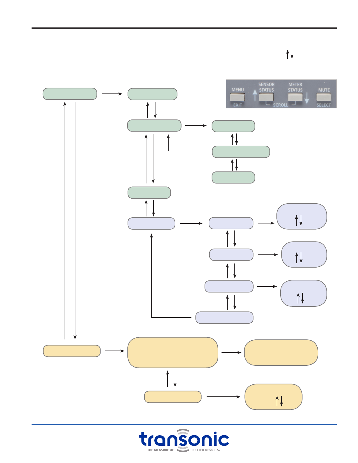
METER CONTROLS
SENSOR CONTROLS
1/4 FLOW SCALE
CALIBRATE SCALE
INVERT FLOW
ALARMS MENU
“CALIBRATION CHOICES”
(Up to 4 factory programmed)
USER ADJ. GAIN
Display selection
& select as active
calibration
SENSOR GAIN
100%
0 VOLT SCALE
1 VOLT SCALE
TO METER OPTIONS
LOFLO ALARM
LO FLOW
min
HIFLO ALARM
HI FLOW
max
REC SIG ALARM THRESHOLD
%
TO METER OPTIONS
A. Program Menu
Press [Menu] to enter the program, this makes the blue button labels active. Use arrows to [Scroll]
through menus and to set values for alarms and gain (pressing and holding scrolls faster). Press [Select]
to enter menus or toggle settings on and off. A star (*) indicates that a selection is made/active. Return to
Measure mode at any point using the [Exit] button.
iv. TS410 Module: Directions For Use
[Select] on*
[Select] on*
[Select] on*
[Select] on*
[Select] on*
[Select] on*
[Select] on*
[Select] on*

14 AU-OPR-400Ser-EN,
Rev D
TS410 Module: Directions For Use
B. Alarms Menu
The TS410 has 3 alarm settings: Low Flow, High Flow and Received Signal. Alarm threshold values are set in
the Program mode. Use the [Scroll] buttons to adjust the threshold from the default value. Default values
are scaled by Sensor size. Alarms are turned on/off in the Program mode using [Select]. NOTE: A star (*)
indicates an alarm is set.
ALL ALARMS TURN OFF AND RESET TO DEFAULT VALUES WHEN SENSOR IS DISCONNECTED OR MODULE TURNED OFF.
When an alarm condition is met, the LCD will ash alarm messages for the specic condition. The LCD
will continue to ash until the condition ends. The message will continue to be displayed on the LCD (not
ashing) to show that the condition occurred. Clear the LCD by pressing any button. NOTE: The button
pressed will also perform its regular function in addition to clearing the LCD screen.
NOTE: The alarm can be re-triggered if the condition is met again without having to reset the alarm in the
program mode. If more than one alarm is set and triggered simultaneously (ie low ow and received signal)
a joint alarm message is displayed. If more than one alarm is triggered sequentially only the most recent
alarm message will be displayed.
If the audible alarm is turned on, an alarm will sound a non adjustable beeping when the condition is met.
The audible alarm will stop if the condition ends. Press the [Mute] button to disable (or enable) the audible
alarm.
NOTE: The mute button is a toggle ON/OFF and must be reset to sound if muted.
LOW FLOW ALARM “LOFLOW”
The low ow alarm is activated when the pulsatile ow signal is lower than the set threshold level. Default
value is minimum ow value (negative ow not zero ow) that the Sensor is specied to detect.
HIGH FLOW ALARM “HIFLOW”
The high ow alarm is activated when the pulsatile ow signal is higher than the set threshold level.
Default value is maximum ow value (positive ow) that the Sensor is specied to detect.
RECEIVED SIGNAL ALARM “REC SIG ALARM”
The Received Signal Alarm is activated when the acoustic signal falls below the set threshold. This alarm can
be used as a gross bubble alarm or detector. The signal amplitude will fall or be interrupted by air or gas
bubbles in the ow circuit. Default value is 0%.
C. Use of Clamp-on Flowsensors
SENSOR SELECTION
Flowsensor size and calibration is determined by the OD of the tubing on which it will be used. Each
Transonic® Clamp-on Tubing Flowsensor is custom calibrated for use on particular tubing (silicone rubber,
latex, polyurethane, or polyvinyl chloride {PVC}). Use on tubing other than specied generally yields
inaccurate measurements and may cause erratic zero baseline drift.
SENSOR CALIBRATION
Flowsensors are precalibrated for a particular tubing and liquid at a certain temperature (see Flowsensor’s
calibration certicate). Recalibration is necessary for accurate measurements at other temperatures or in
other liquids. If a more precise zero baseline than that specied is needed, the Module must be zeroed by
stopping the ow momentarily.

AU-OPR-400Ser-EN,
Rev D
15
SITE SELECTION
The Flowsensor should be applied on straight tubing segments, about 10X the ID from side branches to
produce measurements within its accuracy specications. The best application site for the Flowsensor is
a point well below the highest elevation of the tubing (where gas bubbles might lodge). The Flowsensor
will deform the tube slightly. If the tubing site becomes permanently deformed at one clamping position,
choose another site to achieve better ultrasonic (acoustic) coupling.
TUBING PREPARATION
Apply a layer of petroleum jelly, or silicone grease over the tubing surface to enable ultrasonic transmission
between tube and Sensor. NOTE: Water-based ultrasonic gels should not be used for coupling Clamp-on
Tubing Sensors since they dry out and may build up on the transducer faces. This can cause additional
offset in the measurement and decrease signal quality.
SENSOR APPLICATION
To apply the Flowsensor to tubing, open the Flowsensor's hinged lid, insert lubricated tubing into the
sensing cavity, and close the lid. Fit should be tight, with the full tubing cross section contacting all inner
surfaces of the sensing window. Once the tubing is lled with the liquid to be measured, Flowsensor
operation and signal quality can be conrmed on the Module. Check that the signal quality bars are
illuminated. Low signal quality may indicate that an air or gas bubble is lodged in the tube. Since gas
bubbles block ultrasonic transmission, tilt the tubing and Flowsensor vertically before operating the
Module to ush any bubbles from the sensing window.
FLOW MEASUREMENTS
If using a data acquisition system, calibrate the system prior to beginning measuring. The digital display
presents the average volume ow value in mL/min or L/min. Choose the appropriate [Filter] setting for
average or pulsatile applications.
INVERT FLOW
The arrow on the Sensor points in the direction of positive ow. If the Sensor is installed backwards the
Invert function can change the polarity of the ow outputs without changing the Sensor position. Under
the [Menu], [Select] “Invert Flow” to change the display and outputs to the correct polarity.
LOW FLOW (1/4 SCALE)
Under the [Menu], [Select] “1/4 Flow Scale” to increase the ow gain by a factor of four and increased
sensitivity at low ow rates. The maximum value at the low ow scale is ve times the 1 volt scale value.
Before switching to “1/4 Flow Scale” check to ensure that peak pulsatile ows will not be cut off as this will
cause inaccurate readings. NOTE: When changing the ow scale be sure to recalibrate the data acquisition
system as the 1 volt scale value will change.
CLEANING & STERILIZATION
A Clamp-on Tubing Sensor may be cleaned by wiping with a solution of soap and water (60°C, 140°F).
Because no physical contact is required between the liquid under observation and the Flowsensor,
sterilization is not usually necessary. Standard cold (ethylene oxide) gas sterilization may be used (≤ 60°C,
140°F). The sterile-tubing Flowsensor can be damaged by saline immersion or wet storage and should not
be boiled, autoclaved, or sterilized by cold liquid sterilization.
TS410 Module: Directions For Use

16 AU-OPR-400Ser-EN,
Rev D
D. Use of Inline Flowsensors
SENSOR SELECTION
Flowsensor size is determined by the tubing with which it will be used. Inline Flowsensors are sized based
on the ID of the system tubing.
SENSOR CALIBRATION
Flowsensors are precalibrated for a particular liquid at a certain temperature (see Flowsensor’s calibration
certicate). Recalibration is necessary for accurate measurements at other temperatures or in other liquids.
If a more precise zero baseline than that specied is needed, the Module must be zeroed by stopping the
ow momentarily.
SITE SELECTION
The Flowsensor should be inserted into straight tubing segments about 10X the ID from side branches to
produce measurements within its accuracy specications. The best application site for the Flowsensor is a
point well below the highest elevation of the tubing (where gas bubbles might lodge).
SENSOR APPLICATION
Inline Flowsensors splice into exible tubing circuits. Larger Sensors (4-25PXN) with barbed ends insert into
the tubing. Tubing clamps may be used in high pressure applications to ensure a secure t. Small Sensors (1-
3PXN) with exible tubing ends may be spliced in using a rigid piece of tubing or expanded over the circuit
tubing (see RL-31-tn for PXN installation instructions).
Once the tubing & Sensor are lled with the liquid to be measured, Flowsensor operation and signal quality
can be conrmed on the Module. Check that the signal quality bars are illuminated. Low signal quality may
indicate that an air or gas bubble is lodged in the Sensor. Since gas bubbles block ultrasonic transmission,
tilt the tubing and Flowsensor vertically before operating the Module to ush any bubbles from the
sensing window.
FLOW MEASUREMENTS
If using a data acquisition system, calibrate the system prior to beginning measuring. The digital display
presents the average volume ow value in mL/min or L/min. Choose the appropriate [Filter] setting for
average or pulsatile applications.
INVERT FLOW
The arrow on the Sensor points in the direction of positive ow. If the Sensor is installed backwards the
Invert function can change the polarity of the ow outputs without changing the Sensor position. Under
the [Menu], [Select] “Invert Flow” to change the display and outputs to the correct polarity.
LOW FLOW (1/4 SCALE)
Under the [Menu], [Select] “1/4 Flow Scale” to increase the ow gain by a factor of four and increased
sensitivity at low ow rates. The maximum value at the low ow scale is ve times the 1 volt scale value.
Before switching to “1/4 Flow Scale” check to ensure that peak pulsatile ows will not be cut off as this will
cause inaccurate readings. NOTE: When changing the ow scale be sure to recalibrate the data acquisition
system as the 1 volt scale value will change.
CLEANING & STERILIZATION
An Inline Tubing Sensor may be cleaned by wiping with a solution of soap and water (60°C, 140°F). The
inside of PXN Flowsensors may be cleaned with a soft brush. Care should be taken to avoid scratching the
inside surface of the tube. Standard cold (ethylene oxide) gas sterilization may be used (≤ 60°C, 140°F).
The tubing Flowsensor can be damaged by wet storage and should not be boiled, autoclaved, or sterilized
by cold liquid sterilization. NOTE: Do not use alcohol on small (1-3PXN) Flowsensors as it will damage the
exible tubing.
TS410 Module: Directions For Use
This manual suits for next models
5
Table of contents
Other Transonic Industrial Equipment manuals

Popular Industrial Equipment manuals by other brands

Jct
Jct JES-360Ex operating manual

Grundfos
Grundfos PS.R.05-17 instructions

GSi
GSi DMC Design III Series owner's manual

NCMT
NCMT MAKINO A100-5XR-CD Operator's manual

Gorlitz
Gorlitz GO 68HD Series Operating & maintenance instructions

PCB Piezotronics
PCB Piezotronics 1630-03C Installation and operating manual


