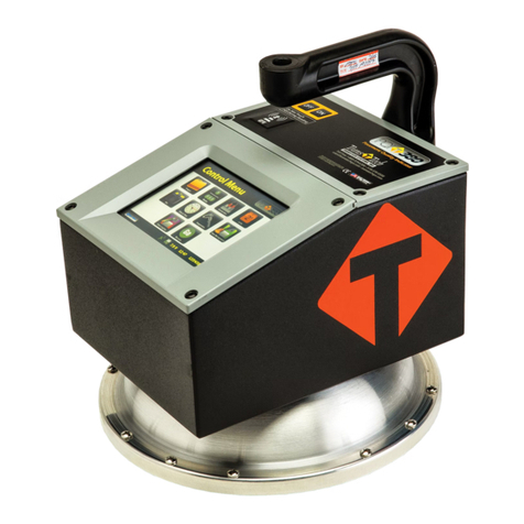
Transtech SDG 200 Service manual

Soil Density Gauge
Operator’s Handbook

Introduction 3
Measurement Technology 3
Application Summary 4
Safety 4
Operating Requirements 4
Controls & Components 5
Contents 5
Gauge Features 6
External Controls 7
Power Save/Auto Shut Down 8
Part 1: Setting up the SDG 8
Installing/Charging the Battery 9
Start Software 10
Main Menu 11
Local Time and Change Date Format 12
Setup GPS 13
Control Menu 14
Select Measurement Units 15
Data Logging 15
Project Details 15
Define, Edit or Upload Material Properties 17
Define and Editing a Material 18
Setting Measurement Offsets 20
Determining Offset Values 22
Upload Material 23
Part 2: Running a Test 24
Measurement Pattern 24
Surface Preparation 24
Measure Density 25
Select a Different Material to Test 28
Part 3: Data Storage and Downloading Data 29
Measurement Data 29
Diagnostic Data 29
Storage Capacity 30
Downloading Data 30
Deleting a Project File 30
Part 4: Maintenance and Troubleshooting 31
Maintenance 31
Troubleshooting 33
Part 5: Definitions and Calculations 33
Measurement Results 33
Definition of Material Properties 34
Part 6: Standardization of SDG 35
Part 7: Explanation of Gradation and Compaction Reports 36
SDG Unit Warranty 44
Table of Contents
2

TransTech’s Soil Density Gauge (SDG) utilizes state of the art technology to get accurate soil density readings.
It’s primary features are:
• No special license or radioactive materials required.
• Lightweight and easy to use.
• 12 hours of portable operation.
• Measures density in common units (pcf or kg/m³).
• Measures percent moisture.
• Stores volumes of readings on internal data logger.
• Data download via USB flash drive (semicolon delimited text file format).
Introduction
Measurement Technology
Using electrical impedance spectroscopy (EIS) the SDG 200’s measurement permits separation of the effects of
density and moisture content on the response of the soil to electromagnetic probing. The density, or compaction
level, is measured by the response of the SDG 200’s electrical sensing field to changes in electrical impedance
of the material matrix. Since the dielectric constant of air is much lower than that of the other soil constituents,
as density/compaction increases, the combined dielectric constant increases because the percentage of air in the
soil matrix decreases. The SDG 200 performs a calculation on the measurement data that enables the device to
report the soil’s density and moisture content.
3

Application Summary
The SDG 200 is intended primarily for making density measurements on a standard 12 inch lift of soil during
or after compaction. It is designed to measure coarse and fine grained materials common in standard soils used
in civil construction projects. After configuring the gauge with soil properties from a standard particle size
distribution report (ASTM D422) and Proctor test (ASTM D698 and D1557) the gauge will provide reliable and
consistent measurements.
Safety
Every effort has been made to make the Soil Density Gauge SDG 200 convenient to use and inherently safe.
The SDG 200 uses non-nuclear, low-voltage direct current to obtain measurements, therefore, there are no
badges, licensing, storage or transport concerns. Like any instrument, however, the user should exercise care
and common sense in its use to prevent mishaps.
Warning
Do not use the unit on or near electrical wiring.
A potential shock hazard exists if contact is made with the exposed wiring.
Warning
Use care in handling the unit. Personal injury can occur through improper handling.
Take proper care to avoid accidentally dropping the unit.
Warning
Unauthorized disassembly of the unit will void the warranty.
Warning
Shipping the gauge with the batteries inside is not recommended.
Caution
Charging the gauge overnight or unattended is not recommended
Caution
Turn the unit off when not in use and during transport.
Caution
Be sure not to switch standardization plates with other gauges. Check the
Serial Numbers located on the gauge and on the plate to be sure they match.
Temperature: -4° to 104° F (-20° to 40° C)
Relative Humidity: 10% to 90% noncondensing
Maximum operating altitude: 10,000 feet (3,050 m)
Disclaimer: TransTech reserves the right to change or modify product design, construction, specifications, or
materials without prior notice and without incurring any obligation to make such changes and modifications on
TransTech products previously or subsequently sold.
Operating Requirements
4

Controls and Components
Contents
The SDG200 is packaged and shipped with the following components. Contact TransTech Systems Inc.
Customer Service if any of the parts are missing.
• SDG200 unit
• Storage/shipping case
• Operators Quickstart Guide
• SDG handle
• 120/220V AC to 12V DC battery charger
• 12V DC Car Charger
• 3 battery packs
5

Gauge Features
USB Port
Used to allow
communication between a
flash drive and the gauge
Charger Port
used to connect the ac
or dc charger to gauge
Infrared
Temperature
Sensor
Used to measure the
surface temperature of
the asphalt
Shroud with
10” Sensor Plate
Location where sensor
plate is located
Battery Door
where the battery
is located
Gauge Shell
Body of the gauge
Handle
Used to carry the gauge
TouchScreen
Used to input and
interact with the
gauge
Faceplate
Protective bezel
for touchscreen
GPS Module
Location of GPS
unit on the gauge
(Accurate to
5+- Meters)
On\Off Button
Turns gauge
on and off
Handle Extension
Used to connect handle
extension
Reflective
Vinyl
safety feature for
operation in dark
areas
6

External/Internal Controls
External controls on the SDG 200 consist of an ON/
OFF switch and 480x640 VGA touch screen display
for navigating through the user interface and entering
alpha/numeric data.
Be sure not to drag your finger from one button to
the next. A firm yet light touch is all that is needed to
navigate from screen to screen.
Unique yet consistent icons are located on most screens for easy one touch navigation. When data input is
required of the operator the screen will display the above keyboard. Toggle from upper to lower case letters
using the Shift button The upper case keyboard gives the option of a minus sign while the lower
case keyboard gives the plus sign Once editing is completed simply Press Enter to store and return
to the previous screen.
7

The numeric keypad as shown in this example allows for only numbers and a decimal point.
Press Accept to store your entry and in most cases return to the previous screen.
The Status Bar is located at the bottom of the screen (excluding the keyboard screens) and will continuously
update the remaining voltage of the batteries while displaying the date, time and status of the GPS and Data
Logging features.
Prior to using the SDG 200 for the first time the gauge will need to be configured to make measurements and
record data correctly.
The following steps must be completed before operating the SDG 200:
1. Installing and Charging the Batteries
2. Starting the Software
3. Set the Local Time/Set Date
4. Set up the GPS
5. Select Units of Measurement
6. Define the material being tested (Material Details)
8. Define Project Details
Setting up the SDG 200
External/Internal Controls
8
The SDG Model 200 has a built in power saving mode. If there are no buttons pressed after approximately 20
minutes the unit will go into a power saving mode. Pressing any key will “Wake” the SDG up for continued
use. If the SDG is left “On” for an hour without any buttons being pressed, it will shut itself down, to conserve
battery run time
Power Save/Auto Shut Down

Installing/Charging the Batteries
To charge the unit, proceed as follows:
1) Turn the SDG 200 unit OFF.
2) Connect the charger to the charger connector located on the back of the SDG 200.
3) Plug the charger into a standard AC outlet.
4) The red indicator lamp will turn green to indicate that the batteries are charged.
5) Unplug the charger from the power source before disconnecting the charger from the SDG 200.
9
You will find a plate on the back of the SDG 200 with 4 spring loaded bolts.
• Turn each bolt approx. 2 full turns until the spring releases
• Remove the plate from the gauge
• Next you will find a wire with a connector, disconnect the battery from the gauge
• Then pull the nylon strap to slide the battery out of the compartment.
(Do Not pull the battery by the connector wire, doing so could cause damage to the battery)
Plug the gauge in and allow the LED to go from red to green for a full charge.
Approximate charge time is 4 hours.

Battery voltage can be viewed on the Status Bar located at the bottom of all screens. A fully charged battery
will display over 8 volts. The battery voltage will decrease as the SDG 200 is used. A low battery icon will be
displayed at approximately 6.5 volts.
The gauge will continue to operate until the battery can not supply enough voltage to complete a measurement.
Once this happens, the gauge will automatically shut down and will not restart until charged. Depending on the
condition of the batteries, once the voltage drops below 6 volts, the gauge may be able to take about 12 to 15
additional readings. It is important to re-charge the battery after each use.
Starting the Software
Turn the SDG 200 on by pressing the ON button. After a few seconds the TransTech splash screen will
appear followed by the Main Menu Screen. The Main Menu screen will display six options. Start SDG200,
Internet (Coming Soon), Calculator, Contact TransTech, GPS Control and Update
Software.
Installing/Charging the Batteries
10

Main Menu
Start button when pressed will
open the Control Menu Screen.
The Internet button when pressed will
open a new screen. The new screen
indicates that this will be an option in
the future. It is not active at this time.
The Calculator button when
pressed will open a screen
which functions as a calculator.
The Contact button when pressed
displays TransTech and distributor
contact information.
The GPS Control button when
pressed will open a screen
which will allow you to enable
or disable the GPS.
The Update Software button will
be used in the event that TransTech
releases an update to the software
Local Time and Change Date Format
You may set the date and time in two locations. From the Main Menu, Press Set Time & Date
located on the status bar or from the Control Menu press Date & Time.
11

To set the time, Press Set Time. Press the appropriate numbers for the time in 24 hour format.
Once you are satisfied with your entry, Press Accept to store and return to the previous screen.
To set the date, Press Set Date. The date will display in either the DD/MM/YY or MM/DD/YY
format which may be toggled from the button located on both screens. As you did with the time, press
the appropriate numbers for the date in the format chosen. Press Accept to store and return to the
previous screen. (Note: Date will be preset by the factory)
12
Local Time and Change Date Format

When the GPS is ON the satellite dish on the status bar turns from red to green.
GPS formatting can also be toggled from the Universal Transverse Mercator (UTM) grid to Latitude/
Longitude (LAT-LON). Initially the display will read Sats 0 for both formats until connections have been
made. The above examples show a connection to five satellites (Sats 5) in both formats. GPS locations will
appear on the bottom left corner of all Reading Mode screens and will store with each reading when Data
Logging is ON.
Setup the GPS
Setting up the GPS is nothing more than turning it on and waiting to connect to satellites. It can
take up to 15 minutes to connect to satellites depending on your location.
From the Main Menu, Press GPS CONTROL. GPS status can be toggled ON or OFF.
13

Opens the project details screen
Starts the standardization process
Opens the material details screen
Opens the diagnostics screen
Opens the units screen. Here you
can toggle, kg/m3-lbs/ft3, F°-C°,
in-mm
Opens the date and time screen
Opens the data management
screen. Here you can delete, down-
load and print job files
Starts the measurement process
Control Menu
From the Main Menu Press Start SDG 200 to obtain the Control Menu. From this menu, you will find
the icons listed below.
14

Select Measurement Units
15
Data Logging
The SDG 200 saves data automatically under the Project name that is current while readings are being taken.
Data stored includes all Project and Mix details as well as Dry Density, Wet Density, Percent Moisture,
Volumetric Moisture, Percent Compaction, Soil Temperature, Date, Time, GPS Position, GPS Time and GPS
Date.
From the Control Menu, Press Units. Density, Temperature and Depth can be toggled independently between
System International (SI “metric”) and U.S. Customary Units. For example, you can set your Density in lb/ft3
while the Temperature is set for Celsius and Depth set to Inches. Press Control Menu on the taskbar to return to
the Control Menu.
Project Details
The SDG 200 is configured to store 10 unique projects that are identified by user entered descriptions. If 10
projects have been defined in the SDG 200 and an 11th project is required, one of the original 10 will need to
be modified to reflect the new project. The details of the new project will need to be input by editing the details
of a previously stored project. Once the old projects are overwritten with new information, the old information
is gone and the new information is saved in the gauge. Previously store data files with the old material
information, however, will not be overwritten.
You may revisit each Project at any given time to continue taking readings. Data from readings taken within
each project will store in the order of which they were taken. If material details change within a project or
project details are added, data for readings taken after the changes will continue to store in the same data file
in the order of which they were taken. Only by changing the Project Name itself will the data be stored in a
separate data file.

Project Details
Keep track of your projects by entering detailed information into Project Details.
The default Projects stored in a new SDG 200 will have generic Project names (i.e. Project1, Project2, etc)
along with generic Project details (i.e. My Street, My Road, Contact). Project Detail screens will resemble the
Material Detail screen such that you are able to select your Project using the up and down arrows.
The green highlighted project is the CURRENT PROJECT. Readings taken will store in a data
file using the CURRENT PROJECT NAME. If the gauge is shutdown, the current project prior to shutdown
will remain the current project when started back up.
Editing Project Details
From the Control Menu, Press Project for the Project Details screen. The project highlighted in green
on the left is displayed in detail on the right. To edit the details of this project, Press Edit Project.
16

There are four black buttons labeled
Project Location Location Contact.
By pressing one of these labeled buttons, you will enter the screen that allows you to store information
for that Project.
For example Press Project, a keyboard allowing you to change the default name will appear. Press
Clear if you would like to start over with a new name. Press Shift to toggle from lower
to upper case letters. Once editing has been completed, Press Enter.
Define, Edit or Upload Material Properties
The density determined by the SDG 200 is highly material dependent so it is extremely important that the
material properties from the Proctor Test and Gradation Report for the soil being tested are input accurately into
the gauge.
The SDG 200 is configured to store 20 unique materials that are identified by user entered descriptions. If 20
materials have been defined in the SDG 200 and a 21st material is required, one of the original 20 will need to
be modified to reflect the material properties of the new material. The properties of the new material will need
to be input by editing the properties of a previously defined material. Once the old material properties are
overwritten with new information, the old information is overwritten and the new information is saved in the
gauge.
The SDG 200 will have default defined materials stored in each of the 20 unique locations. The following
sequence explains how to input new material properties through the keypad or by USB upload and how to edit
previously input material definitions.
Editing Project Details
17

Note: Be sure that the units of the gauge are set for the same units as the material you are uploading.
If, for example, the gauge was set in U.S. Customary units (ex: 150 lb/ft3) and you were to upload the
material in SI units (2402.8 kg/m3) the gauge will notify you that the density is out of range. However, it
will continue to load the material. If you were to switch to SI units AFTER the material has been loaded,
the density would convert the 2402.8 as if it were in lb/ft3 and result in 38,489.2 kg/m3. Correct this
by deleting the material, change the units of the gauge and reload the material or by simply editing the
density in the material setup.
See Part 5 for explanations of the Material Properties.
See Part 6 for explanations of gradation and Proctor test reports.
See Appendix A for explanations of the MTL Generator
Defining and Editing a Material
Define, Edit or Upload Material Properties
Here you may use the green up or down errors to select a new material for editing or change an existing
material. The green highlighted material is the CURRENT MATERIAL that the gauge will use when
taking readings. Prior to exiting this screen, be sure this is the material you want and the information to
the right has been verified. Press Control Menu on the Status Bar (bottom middle) to return to the Control
Menu. If the gauge is shutdown, the current material prior to shutdown will remain the current material when
started back up.
!! Note: The sum of %Greater the 3 inches, %Gravel, %Sand, and %Fines must add up to 100%. The
default values programmed in the SDG software add up to 100%. As soon as one of those values is
edited, the sum will no longer add up to 100% and an error message will be displayed, however, after the
initial error the gauge will allow you to exit and begin taking readings. THIS IS NOT RECOMMENDED
AND WILL GIVE INACCURATE RESULTS!!
!! Note that Max Dry Density and Dry Density Offset must be entered in the same units in which the
gauge is configured to output results. Example: If the gauge is configured to measure in pcf, input Max
Dry Density in pcf !!
18

From the Control Menu, Press Material for the Material Details screen. The material highlighted in
green on the left is displayed in detail on the right. To edit the details of this material, Press
Edit Material.
Defining and Editing a Material
There are fifteen material properties for each material. Eight of these material properties are listed on Page one
of the Edit Material Page and the remaining seven are listed on Page 2. Each can be edited individually by
pressing its corresponding label which prompts a numeric or alpha numeric keypad.
19

The SDG 200 has been designed to determine the moisture and density in a compacted soil sample without
the need for any offsets. The ability to measure moisture and density is based on an empirical model that
was developed by studying common soil types at near optimum moisture contents with typical particle size
distributions. As the SDG 200’s measurement performance is based on this empirical model, there will be
occasions where the soil being measured is so different from one that has been studied previously that an offset
may be required to enable the SDG 200 to produce acceptable results.
Setting Measurement Offsets
Defining and Editing a Material
Once editing is complete, Press the Back button located on Page 2 to verify your changes on the
Material Details page.
20
Other manuals for SDG 200
1
Table of contents
Other Transtech Measuring Instrument manuals
Popular Measuring Instrument manuals by other brands

KAEL Muhendislik Elektronik
KAEL Muhendislik Elektronik ENERGY 11-DIN instruction manual
CDI TORQUE
CDI TORQUE 2503-F-DTC instructions

Contrec
Contrec 500 Series user guide

Quidel
Quidel Sofia quick start guide
Trotec
Trotec PC200 quick start guide

Pfeiffer Vacuum
Pfeiffer Vacuum TPG 362 operating instructions

Bowers
Bowers DigiMic instructions

GretagMacbeth
GretagMacbeth Spectroeye operating manual
Orbit Merret
Orbit Merret OM 621BCD user manual
ROBLON
ROBLON FL 75 Instructions for installation and use

TSI Instruments
TSI Instruments AccuBalance 8370 Operation and service manual

Bosch
Bosch PLR30C quick start guide
