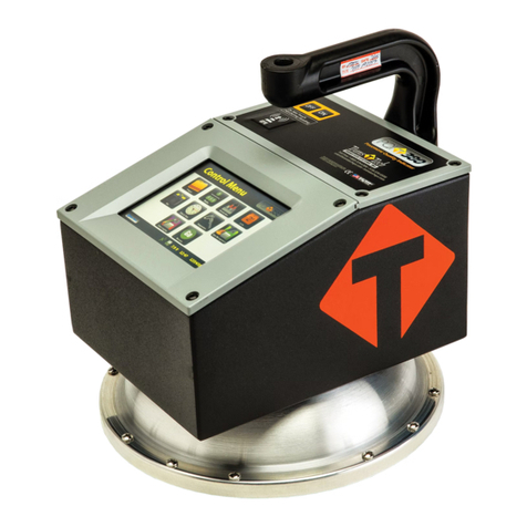
Transtech SDG 200 User manual

Quick Start Guide
Full Manual available online at
www.transtechsys.com/pdf/SDG200Manual.pdf

1-800-724-6306 • www.transtechsys.com
Table of Contents
Contents 3
Charging Batteries 4
Starting the Software 5
GPS Setup 6
Control Menu 7
Unit Settings 8
Material Details 9
Edit Material 10
Project Details 11
Soil Reading 12
Data Management 14
Upload Material 15
Replacement Parts 18
2

SDG200
Standardization
Plate
DC Cord AC Cord
Charger
Handle
Case
Slot for
SDG 200 and
Standardization
Plate
Fold open
compartment
contents
Charger
AC Cord
DC Cord
Handle
Contents
3

1-800-724-6306 • www.transtechsys.com
1. Turn the SDG 200 unit OFF.
2. Connect the charger to the charger connector located on the back of
the SDG 200.
3. Plug the charger into a standard AC outlet.
4. The red indicator lamp will turn green to indicate that the batteries are
charged. (approx. 4hrs)
5. Unplug the charger from the power source before disconnecting the
charger from the SDG 200.
Battery Care Tips
• Whenever uncertain about the battery charge level or condition,
recharge it
• The battery will self-discharge and should NOT be left uncharged for
more than 30 days
• An occasional complete discharge followed by a full recharge is
recommended
• NEVER drop the battery as this can damage the internals
• DO NOT store in freezer or expose to extreme heat
• Battery should be fully charged before use
Charging Batteries
4

Starting the Software
Pressing the ON button will power on the SDG 200. After a few seconds
the TransTech splash screen will appear followed by the Main Menu
screen. The Main Menu screen will display ve options, Start SDG200,
GPS Control, Calculator, Contact TransTech and Update Software.
5

1-800-724-6306 • www.transtechsys.com
GPS Setup
From the Main Menu, press GPS CONTROL. GPS status can be toggled
ON or OFF. When enabled the satellite dish icon on the status bar at the
bottom of the display turns from red to green.
GPS formatting can also be toggled from the Universal Transverse
Mercator (UTM) grid to Latitude/Longitude (LAT-LON). Initially the
display will read Sats 0 for both formats until connections have been
made. The below example shows a connection to ve satellites (Sats 5).
GPS locations will appear on the bottom left corner of the soil reading
screen and will store with each reading when enabled. Press Main Menu
to return to the Main Menu.
GPS Enabled GPS Disabled
Unit SettingsUnit Settings
6

Control Menu
From the Main Menu, press Start SDG 200 to enter the Control Menu.
From this menu, you will select units as well as material and project
information.
Data LoggingData Logging
7

1-800-724-6306 • www.transtechsys.com
Unit Settings
From the Control Menu, press Units. Density, Depth and Temperature
can be toggled independently between system international (SI “metric”)
and U.S. customary units. For example, you can set the density to lb/ft3
while the depth is set to inches and temperature is set for celsius.
8

Material Details
From the Control Menu, press Material to enter the Material Details
screen. The SDG 200 will store twenty detailed materials. The material
highlighted in green on the left is displayed in detail on the right. To edit
the details of this material, press Edit Material.Note: Readings taken
prior to accurately setting up the Material Details will result in
incorrect density results.
9

1-800-724-6306 • www.transtechsys.com
Edit Material
There are fteen material properties for each material. Eight of these
material properties are listed on page one of the edit material screen and
the remaining seven are listed on page 2. Each can be edited individually
by pressing its corresponding label which prompts a keyboard or alpha
numeric keypad. For example, press Material Name, the keyboard will
open allowing you to change the default name. Press Clear if you would
like to start over with a new name. Press Shift to toggle from lowercase
to uppercase letters. Once editing is complete, press the Back button
located on page 2 of the edit material screen to verify your changes on the
material details page.
Coarse
10

Project Details
Keep track of your projects by entering detailed information into the
project details screen. From the Control Menu, press Project. The green
highlighted project is the CURRENT PROJECT. Readings taken will store
in a text le with a .mnt extension using the CURRENT PROJECT NAME.
You may revisit each project at any given time to continue taking readings.
Data within each project will store in the order of which it was taken. To
edit a project, press Edit Project. Press the button of the eld you want to
edit. When editing is complete press the Back button to save and return to
the project details screen.
11

1-800-724-6306 • www.transtechsys.com
Soil Readings
From the Control Menu, press Measure to enter the Soil Reading
screen. The name of the material to be tested and project are displayed
for verication in the bottom right corner. The temperature of the soil is
displayed on the left side of the screen, below that the GPS information is
displayed. The cloverleaf measurement pattern is displayed for your
convenience with the highlighted position being the current position to
measure.
Position the gauge on the soil in position 1 as it appears on the screen
and press 1. Do not touch the gauge while it is busy taking a
measurement. When reading 1 is complete, the gauge will prompt you to
move to location 2. Move the gauge to position 2 and press 2to continue.
Repeat these steps for the remaining three measurements.
12

Soil Readings
After the fth measurement has been taken, the in-place density and
moisture content will be calculated and displayed on the screen. Here you
can choose to Accept or Reject the recording of the averages into the
data le. If you press Accept, you will enter the Enter Location screen
allowing for a description of the location to be entered as well as the
operator name.
13

1-800-724-6306 • www.transtechsys.com
Data Management
From the Control Menu, press Data Management. This is where project
les will be saved, viewed, printed and downloaded.
Download Data - Use the up and down arrows to scroll, highlight the
desired project and press Download DAT & MNT. Insert the USB ash
drive into the USB port, press Download. The gauge will ask if you
inserted the USB drive, once ready, press Download. When downloading
is complete the gauge will display READY.
Viewing a Project File - Use the up and down arrows to scroll, highlight
the desired project and press View. All of your tests saved to this project
will be listed in the order they were taken. Only the most pertinent
information will be shown in this view including: Test Number, Location,
% Moisture, Wet Density, Dry Density, % Compaction. Press the Back
button to exit the Project View screen.
Deleting a Project File - Use the up and down arrows to scroll, highlight
the desired project and press Delete. You will be prompted with a warning
asking if you are sure you wish to delete the le. Once conrmed and
deleted, you will no longer be able to retrieve the measurement data.
Printing a Project File - Plug in your TransTech printer, use the up and
down arrows to scroll, highlight the desired project and press Print.
14

Upload Material
The SDG 200 MTL Generator and MTL File Tool located on the support
disk cd-rom (included in your kit) generates the text les needed to upload
material data into the Material Details section of your gauge. Please see
the SDG 200 Operator’s Handbook for details on how to generate text
les. Once your les are loaded onto a USB ash drive, insert the drive
into the USB port on the back of the SDG 200. From the Control Menu,
press Material, then press Upload Material.
15

1-800-724-6306 • www.transtechsys.com
Upload Material
Be sure to have your USB drive inserted into the USB port located on
the back of the gauge then press Upload. The le name of the materials
located on the USB drive will appear on the left and some details
identifying that specic material will be displayed on the right. Use the up
or down arrows to highlight the material you wish to upload. Once veried,
press Select to upload the material information into the gauge. Press
Back to view the uploaded material in detail.
16

Upload Material
Note: Be sure that the units of the gauge are set for the same units
as the material you are uploading. If the gauge was set in U.S.
Customary units (ex: 150 lb/ft3) and you upload the material in SI
units (2402.8 kg/m3) the gauge will notify you that the density is out
of range. However, it will continue to load the material. If you switch
to SI units AFTER the material has been loaded, the density would
convert the 2402.8 as if it were in lb/ft3and will result in
38,489.2 kg/m3.
Correct this by deleting the material, change the units of the gauge
and reload the material or by simply editing the density in the
material setup.
17

1-800-724-6306 • www.transtechsys.com
To order parts call the TransTech service department at 1-800-724-6306
Replacement Parts
7500-0320
SDG 200 AC Charger
7500-0292
SDG 200 DC Vehicle
Charger
7500-0235
SDG 200 Extension
Handle Kit
1400-0028
SDG 200 StrongHold
Carry Case
8000-0061
SDG 200 Replacement
StandO Feet Kit
2100-0159
SDG 200 Charging Port
Dust Cap
18

Replacement Parts
To order parts call the TransTech service department at 1-800-724-6306
7000-0336
SDG 200 Generation 2
Replacement Battery Door
7500-0356
SDG 200 Generation 2
Battery
7500-0354
SDG 200 Generation 1
Battery Cap with Spring
8000-0063
SDG 200 Generation 1
Battery (3 Pack)
19

900 Albany Shaker Road, Suite 2
Latham, NY 12110
Phone: 518-370-5558
Toll Free: 1-800-724-6306
Fax: 518-370-5538
Email: [email protected]
Web: www.transtechsys.com
Toll Free: TransTech.Systems.Inc01
Follow us on
Rev-
03/2021
Other manuals for SDG 200
1
Table of contents
Other Transtech Measuring Instrument manuals
Popular Measuring Instrument manuals by other brands

KAEL Muhendislik Elektronik
KAEL Muhendislik Elektronik ENERGY 11-DIN instruction manual
CDI TORQUE
CDI TORQUE 2503-F-DTC instructions

Contrec
Contrec 500 Series user guide

Quidel
Quidel Sofia quick start guide
Trotec
Trotec PC200 quick start guide

Pfeiffer Vacuum
Pfeiffer Vacuum TPG 362 operating instructions

Bowers
Bowers DigiMic instructions

GretagMacbeth
GretagMacbeth Spectroeye operating manual
Orbit Merret
Orbit Merret OM 621BCD user manual
ROBLON
ROBLON FL 75 Instructions for installation and use

TSI Instruments
TSI Instruments AccuBalance 8370 Operation and service manual

Bosch
Bosch PLR30C quick start guide
