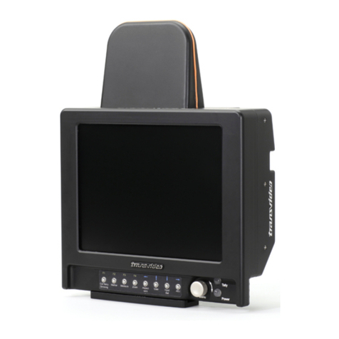
Transvideo CineMonitorHD63DView evolution User manual

Rev. 0.0
Jan 4th 2010
Doc ref:
CineMonitorHD3DView evolution
Operator Manual
cev.fr


Page 3
Rev.0.0
CineMonitorHD3DView evolution
Jan 4th 2010
Figure 3 - CineMonitorHD3DView6 back (SDI Only)

Page 5
Rev.0.0
CineMonitorHD3DView evolution
Jan 4th 2010
About
This Operator Manual describes the use of the TRANSVIDEO
CineMonitorHD3DView “evolution” family.
The first CineMonitor has been introduced to the Film Industry during year 1995.
The CineMonitorHD3DView “evolution” is our latest contribution to the Digital
Cinematography Stereoscopic world, including advanced decision tools for the
HD3D filmmaker.
The CineMonitorHD3DView evolution family includes the following products:
CineMonitorHD63DView evolution 6” HD 3DView Monitor
CineMonitorHD103DView evolution 10” HD 3DView Monitor
CineMonitorHD123DView evolution 12” HD 3DView Monitor
CineMonitorHD153DView evolution 15” HD 3DView Monitor
If the physical, electrical and optical characteristics of the products are different,
the user interface is the same.
Several configurations are optionally available for this family of products.
There is the choice at the order between several input boards, which gives
different functionalities described in this document. Some options can be not
implemented in your CineMonitorHD3DView.
It is possible to upgrade the CineMonitorHD3DView, for that, please contact your
local Transvideo representative.
The products described in this book are professional equipments; they are not
designed for consumer use. Utilization of these products implies knowledge of
basics in video signal management, HDTV and film making concept.

Page 6
Rev.0.0
CineMonitorHD3DView evolution
Jan 4th 2010
Table of content
CONDENSED OPERATING INSTRUCTIONS................................................................................................................9
INTRODUCTION............................................................................................................................................................10
Unpacking and Inspection..............................................................................................................................................10
Safety Inspection............................................................................................................................................................10
Product Overview ...........................................................................................................................................................11
Front Panel Controls and Indicators.........................................................................................................................11
Rear Panel Controls and Connectors.......................................................................................................................11
Installation.................................................................................................................................................................12
Instrument Positioning ..............................................................................................................................................12
Power Requirements ................................................................................................................................................13
OPERATION...................................................................................................................................................................14
Start-Up & Power............................................................................................................................................................14
Using the direct access functions...................................................................................................................................14
F1…F4............................................................................................................................................................................14
Using the menus.............................................................................................................................................................15
Direct functions description ............................................................................................................................................16
ENERGY MODE.......................................................................................................................................................16
MARKERS ................................................................................................................................................................16
Rotating knob......................................................................................................................................................17
Measure (Waveform, Vectorscope, Histogram).......................................................................................................18
Rotating knob......................................................................................................................................................20
Considerations about the use of measurement tools in 3DView mode..............................................................21
1. ZOOM.............................................................................................................................................................22
Arrows & Rotating knob ......................................................................................................................................22
ASPECT RATIO........................................................................................................................................................22
USER........................................................................................................................................................................23
INPUT .......................................................................................................................................................................25
ADJUST ....................................................................................................................................................................26
MENU FUNCTIONS.......................................................................................................................................................27
ADJUSTMENTS .......................................................................................................................................................27
HUE (TINT) .........................................................................................................................................................27
BRIGHTNESS.....................................................................................................................................................27
CONTRAST.........................................................................................................................................................27
SATURATION .....................................................................................................................................................27
BLUE CHECK...........................................................................................................................................................27
COLORIMETRY........................................................................................................................................................27
MANUAL .............................................................................................................................................................27

Page 7
Rev.0.0
CineMonitorHD3DView evolution
Jan 4th 2010
D56......................................................................................................................................................................28
D65......................................................................................................................................................................28
GAMMA.....................................................................................................................................................................28
GAMMA ADJUST................................................................................................................................................28
STANDARD 0.45 ................................................................................................................................................28
Use in LINEAR....................................................................................................................................................28
LOCK ........................................................................................................................................................................28
TOOLS......................................................................................................................................................................29
AUDIO.................................................................................................................................................................29
TIMECODE .........................................................................................................................................................30
COOKE LENS.....................................................................................................................................................31
FOCUS HELPER ................................................................................................................................................32
FRAMELINE........................................................................................................................................................32
HORIZON (if option installed).............................................................................................................................34
LIMITS.................................................................................................................................................................35
MAX LEVEL...................................................................................................................................................35
WHITE CLIPPING.........................................................................................................................................35
BLACK CLIPPING.........................................................................................................................................35
MIN LEVEL....................................................................................................................................................35
SORIN’s MARKER........................................................................................................................................35
SORIN’s MARHER WIDTH...........................................................................................................................36
OVEREXPOSURE: ON/OFF ........................................................................................................................36
SORIN’S MARKER: ON/OFF........................................................................................................................36
BLACK LIMITS: ON/OFF ..............................................................................................................................36
MEASUREMENT ................................................................................................................................................37
SIGNAL ANALYSIS.......................................................................................................................................37
OVEREXPOSURE: ON/OFF ........................................................................................................................37
SORIN’S MARKER: ON/OFF........................................................................................................................37
BLACK LIMITS: ON/OFF ..............................................................................................................................37
1 LINE............................................................................................................................................................37
12 LINES .......................................................................................................................................................37
ALL LINES.....................................................................................................................................................37
Background INTENSITY ...............................................................................................................................37
SPOT INTENSITY.........................................................................................................................................37
RETICULE INTENSITY.................................................................................................................................37
TALLY .................................................................................................................................................................38
NORMAL.............................................................................................................................................................39
HORIZONTAL FLIP ............................................................................................................................................39
VERTICAL FLIP..................................................................................................................................................39
PICTURE REVERSE ..........................................................................................................................................40
AUTO REVERSE................................................................................................................................................40
AUTO FLIP VERTICAL ONLY............................................................................................................................40
3D..............................................................................................................................................................................41
GRID ...................................................................................................................................................................41
MODE..................................................................................................................................................................42
COLORS.............................................................................................................................................................42
FLOP...................................................................................................................................................................43
FLIP.....................................................................................................................................................................43
HORIZ SHIFT......................................................................................................................................................43
DISPLAY MODE.......................................................................................................................................................44
COLOR................................................................................................................................................................44
GREEN................................................................................................................................................................44
B&W ....................................................................................................................................................................44
TECHNICAL..............................................................................................................................................................44
CVBS STD SELECT...........................................................................................................................................44
NTSC...................................................................................................................................................................44
REVERSE SCROLLING.....................................................................................................................................44
ACCESSORY......................................................................................................................................................45
COMPONENT RGB......................................................................................................................................45
COMPONENT YPrPb....................................................................................................................................45

Page 8
Rev.0.0
CineMonitorHD3DView evolution
Jan 4th 2010
CVBS.............................................................................................................................................................45
VOLTAGE ALARM..............................................................................................................................................45
VOLTAGE DISPLAY .....................................................................................................................................45
VOLTAGE ALARM LEVEL............................................................................................................................45
VOLTAGE ALARM DISPLAY........................................................................................................................45
POSITION .....................................................................................................................................................45
EXIT TEMPO ......................................................................................................................................................45
LED DIMMER......................................................................................................................................................46
MEMORY..................................................................................................................................................................46
MEM 1 … MEM 4................................................................................................................................................46
SAVE.............................................................................................................................................................46
RECALL.........................................................................................................................................................46
PRESET..............................................................................................................................................................46
PRESET ALL INPUTS ..................................................................................................................................46
PRESET SELECTED INPUT........................................................................................................................46
SERVICE & MAINTENANCE.........................................................................................................................................47
General...........................................................................................................................................................................47
Useful tips.......................................................................................................................................................................47
CLEANING................................................................................................................................................................47
FULL RESET............................................................................................................................................................47
Software and Firmware ..................................................................................................................................................48
Calibration.......................................................................................................................................................................48
Product Return................................................................................................................................................................48
ACCESSORIES..............................................................................................................................................................49
SPECIFICATIONS..........................................................................................................................................................51
CONNECTORS..............................................................................................................................................................53
TRANSVIDEO EQUIPMENT LIMITED WARRANTY ....................................................................................................54

Page 9
Rev.0.0
CineMonitorHD3DView evolution
Jan 4th 2010
WARNING and CAUTION
WARNING: There is very high voltage inside of the component. Risk of injury
or death.
WARNING: This product must be used in a correct grounded electrical
environment; ground defects can create severe problems to the equipment, the
picture quality and even cause danger for the user.
WARNING: Copyright law and international treaties protect this product, its
design and its software. One or several international patents apply to the
“CineMonitorHD3DView evolution”.
Unauthorized reproduction or distribution of this product or its design or its
software or any portion of them, may result in severe civil and criminal
penalties, and will be prosecuted to the maximum extent possible under the
law.
CAUTION: Warranty is void is the product is opened. The unit contains
electrostatic sensitive devices, which can be damaged or destroyed if you touch
them. Refer to the standard ESD procedures before disassembly of the
component. Very high voltage are present in the unit, there is some risk of
electric shock if opened by a non-accredited technician.
Condensed Operating Instructions
①Connect an adapted power supply to the XLR connector or a battery if
any socket available.
②Connect a video source to the input
③Switch on the monitor with the back switch
④Select the correct input with INPUT SEL
For more information, please read the manual in SECTION III “OPERATION”

Page 11
Rev.0.0
CineMonitorHD3DView evolution
Jan 4th 2010
Product Overview
Front Panel Controls and Indicators
Rear Panel Controls and Connectors

Page 12
Rev.0.0
CineMonitorHD3DView evolution
Jan 4th 2010
Installation
The CineMonitorHD3DView must be securely fixed on the camera or on the
location of use. TRANSVIDEO manufactures high quality brackets and
accessories for the comfort of use and security for the equipment and user.
Do not use the monitor with loose fixation or damaged brackets it is a question
of security for yourself and other persons working on the same location.
Several fixation points have been added to this equipment for secured
professional use.
①A slide with a ¼-20” nut is delivered as standard equipment with the
product. This slide is fixed on the bottom of the monitor.
②One or several optional slides can be attached to the sides, back or top
of the monitor. 2 x M4 screws attach the slides. Several TRANSVIDEO’s
accessories can be fixed in these positions; this mounting system is generic for
Transvideo since 1990.
③One square of 20mm accepts 4xM3 screws.
Instrument Positioning
The CineMonitorHD3DView needs to be in a ventilated area to be normally
cooled.
Long use in closed environment without ventilation can damage the monitor.
Never use the monitor in a plastic bag.
Never use the monitor in full sun with a Raincover.

Page 13
Rev.0.0
CineMonitorHD3DView evolution
Jan 4th 2010
Power Requirements
Only DC Voltage powers this product.
AC voltage can be used with an appropriate AC/DC converter
Recommended power adaptors:
CineMonitorHD63DView evolution Transvideo AL24
CineMonitorHD103DView evolution Transvideo AL80
CineMonitorHD123DView evolution Transvideo AL80
CineMonitorHD153DView evolutionTransvideo AL80
The input power voltage range is extremely wide from 10 to 36 V DC (except
specified differently).
The power consumption slightly varies with the input voltage, the operating
temperature and the configuration of the product.
The power supply is protected against reverse polarity.
Over voltage may cause severe damages to the equipment.
For safety of use the CineMonitorHD3DView family feature a galvanic insulation
of the DC input. Do not connect the power ground to the chassis of the monitor
or to the metallic body of the power connector to keep the galvanic insulation.
The galvanic insulation is rated at 1000VDC. The chassis of the monitor is
connected to the video ground.

Page 14
Rev.0.0
CineMonitorHD3DView evolution
Jan 4th 2010
Operation
Start-Up & Power
The ON/OFF Switch is placed on the back of the monitor.
The product needs a certain time to reach its nominal brightness.
This time can vary with the temperature.
When using the optional Battery Holder, the switch of the battery holder
overpasses the switch of the monitor.
In OFF position, the power consumption is null.
WARNING RISK OF FIRE: It is always recommended to remove the power
source from the monitor when you do not use it and/or when you travel.
Especially if you place the monitor in a closed environment (bag, box, …)
Using the direct access functions
Several direct functions are available from the keypad.
One short press on the pad allows access to the functionalities.
One long press (more than 2 seconds) on the pad allows access to the optional
functionalities for the related function (if any).
The rotating knob is a rotary encoder with a push function, it is used to access
and navigate in the menus, adjust some parameter values, validate and exit
functions by pushing it.
A short push when on “EXIT” exits of the current menu to the previous level (if
any) a long push exits from the menu.
F1…F4
One long press (more than 2 seconds) on the direct function pad allows to
access to the optional functionalities for the related function (if any).
Depending of the function, options and environment, the content of F1 … F4 can
vary. Pressing the pad just under the engraving will activate or deactivate the
sub-function. The activated sub-function is highlighted on the menu by an
orange text, un-activated function is displayed in white.
In some specific case, F4 can extend the selection to a second page of sub-
menu.

Page 15
Rev.0.0
CineMonitorHD3DView evolution
Jan 4th 2010
Using the menus
The menu gives access to functionalities that do not have direct access from the
keypad.
The rotating knob is used to navigate in the menu structure.
Pushing the rotating knob allows to access to the function sub-menu.
Exit of the menu by selecting EXIT or by automatic temporization (temporization
can be adjusted in the TECHNICAL Menu)
Some feature described in this manual could be optional.
If your monitor do not show the feature described in this manual, please check
first if you bough the described option. You can contact your distributor to
upgrade your product and/or to install some optional tools.

Page 16
Rev.0.0
CineMonitorHD3DView evolution
Jan 4th 2010
Direct functions description
ENERGY MODE
Allows switching between different modes:
FULL BRIGHT: Maximum brightness and power consumption, the color
calibration is deactivated.
CALIBRATED: Standard mode, the brightness and white point are
calibrated according to the settings of MENU/COLORIMETRY
USER: Brightness is adjustable from 10% to 100%, color
calibration is preserved. Allows having a reduced power mode between two
takes.
F1: D56
F2: D65
F3: MANUAL (Adjustable in MENU/COLORIMETRY/)
It is necessary to wait a few seconds after pressing the pad before loading of the
correct lookup table
MARKERS
Displays the markers selected with F1…F4
Not active when the ZOOM or FORMAT 2.40:1 are selected
This menu is contextual; some functions can be unavailable depending of the
input format.
F1: 4:3
F2: 14:9
F3: 16:9
F4: ->
Next page
FI: SAFE area
F2 3D Grid*
F4: <-
* The grid is available in 3DView mode and is a specific tool for stereographic
work which have been developed in cooperation with Alain Derobe AFC,

Page 17
Rev.0.0
CineMonitorHD3DView evolution
Jan 4th 2010
Stereographer and 3D consultant. This grid is mainly used to adjust the far planes
parallax to the target screen size.
It is a vertical parallel grid with adjustable width between the lines.
In zoom mode the grid is sized to the native resolution. The grid can be adjusted
in MENU/3D/GRID/… or during the selection and call of the function through the
MARKER direct access pad.
Rotating knob
To adjust the offset of the 3D Grid when pushing shortly on MARKER and with
grid selected. The offset of the grid, or horizontal positioning, is adjustable of
plus or minus half of the value of the grid.
By pressing more than 3 seconds the “MARKER” pad when the grid is displayed,
it is possible to modify the step of the grid from 1 to 123 pixels. During selection,
it is possible to adjust the width of the grid with the rotating knob.

Page 18
Rev.0.0
CineMonitorHD3DView evolution
Jan 4th 2010
Measure (Waveform, Vectorscope, Histogram)
Displays the selected measurement tools.
The brightness of the reticule and of the spot can be adjusted in the TECHNICAL
MENU
White and black clipping alert can be configured in MENU/TOOLS/LIMITS/, the
same limits are used for the waveform monitor and the histogram representation.
Setting these limits is useful to have a visual alert on the waveform and
histogram representation of the video signal if there is a risk of overexposure or
of loss of black details.
F1: WAVEform
F2: HISTOgram
F3: VECTORscope
Selecting F1:WAVE gives access to an other sub-menu:
F1: LINE
Displays one a single spot, Y, Red, Green or Blue

Page 19
Rev.0.0
CineMonitorHD3DView evolution
Jan 4th 2010
F2: PARADE
Displays Y, R, G , B, Pr & Pb in parade mode.
Available modes:
Y R G B / Y G B R
R G B / G B R
Y Cr Cr
F3: FRAME
Displays Y, R, G or B in frame mode. (also named sweep mode)
The content of one frame/picture is displayed.
Selecting F2:HISTOGRAM displays directly the representation:
F4: Return to the previous menu.
Selecting F3:VECTOR displays directly the representation:

Page 20
Rev.0.0
CineMonitorHD3DView evolution
Jan 4th 2010
Rotating knob
When a measurement tool is displayed. Pressing the WFM pad gives the
possibility to adjust the representation by using the rotating knob.
Histogram : Adjustment of the scale of the histogram

Page 21
Rev.0.0
CineMonitorHD3DView evolution
Jan 4th 2010
Waveform : 3 sizes of waveform are available
The background transparency in overlay mode can be adjusted
in MENU/MEASURE
Considerations about the use of
measurement tools in 3DView mode
When using the 3DView mode the tool’s spot displays the two inputs
simultaneously. It is valid for the Waveform, Histogram and Vectorscope.
To identify clearly the source, each spot uses a specific color.
The colors used are the same as those selected for the Anaglyph/Monochrome
mode.
The selection of the color is done in MENU/3D/…
i.e. Using the HISTOGRAM with RED CYAN colors will display input 1 in RED and
input 2 in CYAN. The common values of the HISTOGRAM will be displayed in
white, the differences in BLUE or CYAN.
i.e. Using the HISTOGRAM with RED/BLUE colors will display input 1 in RED and
input 2 in BLUE. The common values of the HISTOGRAM will be displayed in
MAGENTA, the differences in RED or BLUE.

Page 22
Rev.0.0
CineMonitorHD3DView evolution
Jan 4th 2010
ZOOM
Displays the HD picture in full resolution mode (pixel to pixel).
Depending of the input format, the magnification ratio can be different.
Displays the SD picture in full screen. In this case there is an important
magnification ratio applied to the original picture, the resultant picture includes
created pixels and lines and cannot be considered as a proof. In this mode the
waveform will be superimposed to the picture.
Arrows & Rotating knob
In zoom mode arrows move the picture on Top/Bottom, Left/Right positions; Fine
adjustment can be made by rotating the rotating knob.
A long push on the ZOOM pad centers the picture, the next push sends back to
the full picture display.
During the zoom mode a pictogram is displayed in the right side of the tool zone.
This pictogram indicates the relative position of the magnified zone in the original
picture.
ASPECT RATIO
Allows the change of aspect ratio between:
1.33:1 4/3 SD only
1.78:1 16/9 HD & SD
2.40:1 HD & SD
This manual suits for next models
3
Table of contents
Other Transvideo Monitor manuals

Transvideo
Transvideo CineMonitor HD 3DView series User manual

Transvideo
Transvideo CineMonitorHD Evolution User manual

Transvideo
Transvideo Stargate Series User manual

Transvideo
Transvideo Rainbow HD User manual

Transvideo
Transvideo Stargate User manual

Transvideo
Transvideo CineMonitor HD 3DView series User manual

Transvideo
Transvideo Starlite RF User manual

Transvideo
Transvideo RainbowHD User manual

Transvideo
Transvideo cinemonitorhd User manual

Transvideo
Transvideo CineMonitorHD 3DView Evolution User manual