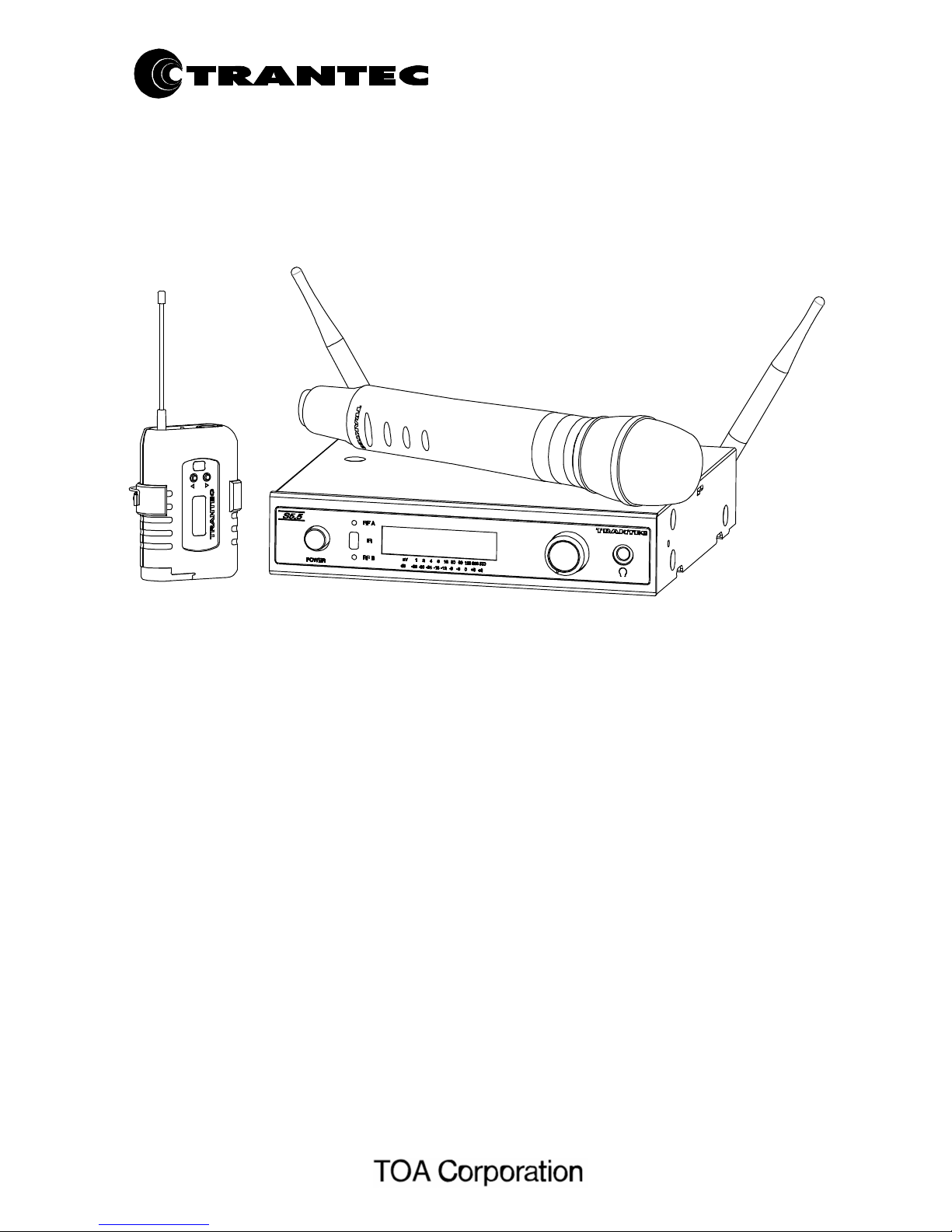
Trantec S5.5 series User manual
OPERATING
INSTRUCTIONS
WIRELESS MICROPHONES SYSTEM
S5.5 series
CONTENTS
1. SAFETY PRECAUTIONS
2. GENERAL DESCRIPTION
3. FEATURES
4. HANDLING PRECAUTIONS
5. NOMENCLATURE AND FUNCTIONS
6. RECEIVER FREQUENCY SELECTION
7. MISCELLANEOUS SETTINGS ON
RECEIVER
8. HANDHELD MICROPHONE SET-UP
9. BELTPACK TRANSMITTER SET-UP
10. BATTERY INDICATON
11. S5 Series Rack Mount Kit
12. Mini-XLR Wiring Connections
13. OPERATIONAL HINTS
14. TROUBLESHOOTING
15. CERTIFICATIONS
16. SPECIFICATIONS
Thank you for purchasing TOA's TRANTEC S5 series Wireless Microphone system.
Please carefully follow the instructions in this manual to ensure long, trouble-free use of your equipment.
2
1. SAFETY
PRECAUTIONS
• Be sure to read the instructions in this section carefully before use.
• Make sure to observe the instructions in this manual as the conventions of safety symbols and messages
regarded as very important precautions are included.
• We also recommend you keep this instruction manual handy for future reference.
Safety Symbol and Message
Conventions
Safety symbols and messages described below are used in this manual to prevent bodily injury and property
damage which could result from mishandling. Before operating your product, read this manual first and
understand the safety symbols and messages so you are thoroughly aware of the potential safety hazards.
WARNING
Indicates a potentially hazardous situation
which, if mishandled, could result in death or
serious personal injury.
When Installing the Receiver
• Do not expose the unit to rain or an environment where it may be splashed by water or other liquids, as
doing so may result in fire or electric shock.
• Use the unit only with the voltage specified on the unit. Using a voltage higher than that which is specified
may result in fire or electric shock.
• Do not cut, kink, otherwise damage nor modify the power supply cord. In addition, avoid using the power
cord in close proximity to heaters, and never place heavy objects -- including the unit itself -- on the power
cord, as doing so may result in fire or electric shock.
• Avoid installing or mounting the unit in unstable locations, such as on a rickety table or a slanted surface.
Doing so may result in the unit falling down and causing personal injury and/or property damage.
• To prevent lightning strikes, install the unit at least five meters away from a lightning rod, and yet within the
protective range (angle of 45°) of the lightning conductor. Lightning strikes may cause a fire, electric shock
or personal injury.
• Since the unit is designed for in-door use, do not install it outdoors. If installed outdoors, the aging of parts
causes the unit to fall off, resulting in personal injury. Also, when it gets wet with rain, there is a danger of
electric shock.
When the Receiver is in Use
• Should the following irregularity be found during use, immediately switch off the power, disconnect the power
supply plug from the AC outlet and contact your nearest TOA dealer. Make no further attempt to operate the
unit in this condition as this may cause fire or electric shock.
· If you detect smoke or a strange smell coming from the unit.
· If water or any metallic object gets into the unit
· If the unit falls, or the unit case breaks
· If the power supply cord is damaged (exposure of the core, disconnection, etc.)
· If it is malfunctioning (no tone sounds.)
• Do not place cups, bowls, or other containers of liquid or metallic objects on top of the unit. If they
accidentally spill into the unit, this may cause a fire or electric shock.
• Do not touch the unit's antennas during thunder and lightning, as this may result in electric shock.
When the Microphone or the Transmitter is in Use
• To prevent the electromagnetic wave from badly influencing medical equipment, make sure to switch
off the unit's power when placing it in close proximity to the medical equipment.
CAUTION
Indicates a potentially hazardous situation which, if mishandled,
could result in moderate or minor personal injury, and/or property
damage.
When Installing the Receiver
• Never plug in nor remove the power supply plug with wet hands, as doing so may cause electric shock.
• When unplugging the power supply cord, be sure to grasp the power supply plug; never pull on the cord
itself. Operating the unit with a damaged power supply cord may cause a fire or electric shock.

3
• When moving the unit, be sure to remove its power supply cord from the wall outlet. Moving the unit with the
power cord connected to the outlet may cause damage to the power cord, resulting in fire or electric shock.
When removing the power cord, be sure to hold its plug to pull.
• The socket outlet shall be installed near the equipment and shall be easily accessible.
• Avoid installing the unit in humid or dusty locations, in locations exposed to the direct sunlight, near the
heaters, or in locations generating sooty smoke or steam as doing otherwise may result in fire or electric
shock.
When the Receiver is in Use
• Do not place heavy objects on the unit as this may cause it to fall or break which may result in personal injury
and/or property damage. In addition, the object itself may fall off and cause injury and/or damage.
• Make sure that the volume control is set to minimum position before power is switched on. Loud noise
produced at high volume when power is switched on can impair hearing.
• Never open the unit case as there are high temperature parts inside the unit, which may cause a burn if
touched. Refer all servicing to your nearest TOA dealer.
• Use the dedicated AC adapter for the unit. Note that the use of other adapter may cause a fire.
• If dust accumulates on the power supply plug or in the wall AC outlet, a fire may result. Clean it periodically.
In addition, insert the plug in the wall outlet securely.
• Switch off the power, and unplug the power supply plug from the AC outlet for safety purposes when cleaning
or leaving the unit unused for 10 days or more. A fire or electric shock may result.
• Any modifications made to this device that are not approved by TOA Corporation may void the authority
granted to the user to operate this equipment.
• Operation of this device is subject to the following two conditions: (1) this device may not cause interference,
and (2) this device must accept any interference, including interference that may cause undesired operation
of the device.
When the Microphone or the Transmitter is in Use
• When the unit is not in use for 10 days or more, be sure to take the battery out of the unit because battery
leakage may cause personal injury or contamination of environment.
• Make sure to observe the following handling precautions so that a fire or personal injury does not result from
leakage or explosion of the battery.
· Do not short, disassemble heat nor put the battery into a fire.
· Do not solder a battery directly.
· Be sure to use the specified type of battery
· Note correct polarity (positive and negative orientation) when inserting a battery in the unit.
· Avoid locations exposed to the direct sunlight, high temperature and high humidity when storing batteries.
• When the battery becomes inflated or leaks, discontinue use and replace with new one immediately
CAUTION TO USER: Changes or modifications not expressly approved by the party responsible for
compliance could void the user's authority to operate the equipment.
IMPORTANT NOTE: To comply with the FCC RF exposure compliance requirements, no change to the
antenna or the device is permitted. Any change to the antenna or the device could result in the device
exceeding the RF exposure requirements and void user’s authority to operate the device.
IMPORTANT NOTE:
This device complies with Industry Canada’s licence-exempt RSSs. Operation is subject to the following two
conditions:
(1) This device may not cause interference; and (2) this device must accept any interference, including
interference that may cause undesired operation of the device.
Le prés ent appareil est co nforme aux CNR d'Industrie Canada applicables aux appareils radio exempts de
licence. L'exploitation est autorisée aux deux conditions suivantes : (1) l'appareil ne doit pas produire de
brouillage, et (2) l'utilisateur de l'appareil doit accepter tout brouillage radioélectrique subi, même si le
brouillage est suscepti ble d'encompromettre le fonctionnement.

4
2. GENERAL
DESCRIPTION
The TOA’s TRANTEC S5 series W i r e l e s s M i c r o p h o n e s y s t e m is designed for use on the UHF
f r e q u e n c y band, and suitable for vocal or speech reinforcement applications. It features a compander
circuit which minimizes the influence of ambient noise.
24 User selectable channels that can be operated simultaneously. (depending on region)
10 preset banks including 1 custom user.
S5 series HDX Wireless handheld Microphone employs a fine, powerful dynamic microphone unit.
S5 series HCX Wireless handheld Microphone employs a fine condenser micrpphone unit.
S5 series BTX Wireless belt-pack transmitter can use TRANTEC series lavalier microphones and headset
microphones .
S5 series RX Wireless receiver is a true diversity receiver to minimize drop-outs.
3.
FEATURES
• An optimized PLL-synthesizer minimizes the oscillation frequency drift resulting from the ambient temperature
or voltage fluctuation.
• Intuitive LCD and operating system on both receiver and transmitter.
• Infra-red programming for fast system set-up.
• Software transmitter function locks.
• Headphone monitoring as standard.
• Up to 10 hours of continuous use with single AA alkaline battery.
• S5 series handheld microphone employs a built-in antenna.
• The state of battery consumption can be displayed on S 5 s e r i e s R X receiver's indicator.
• Quick channel scanning.
• AF processing menu.
• Fully integrated PC software monitoring facility via USB port.
• All metal construction of receiver and transmitters.
• Rack kit and front mounting antenna adaptors included.
• Compact size and high reliability
4. HANDLING
PRECAUTIONS
• Do not expose the unit to rain or an environment where it may be splashed by water or other liquids,
as doing so may result in unit failure.
• Never open nor remove the unit case to modify the unit. Refer all servicing to your nearest TOA
dealer.
• Take care not to drop the unit onto the floor nor bump it against a hard object as the unit could fail.
• Do not place the unit in locations of high temperature (ex. in an ill-ventilated car in summer) or high
humidity as the unit could fail.
• Do not use the unit in locations where it is exposed to seawater.
• Avoid using a mobile telephone near the wireless microphone in use. Noise could be picked up.
• When installing, keep the unit as far away as possible from fluorescent lamps, digital equipment,
personal computers, and other equipment that generate high frequency noise.
• To clean, use a dry cloth. When the unit gets very dirty, wipe lightly with a cloth damped in a dilute
neutral cleanser, then wipe with a dry cloth. Never use benzene, thinner, or chemically-treated
cleaning towel.
• When using two or more wireless microphones, keep them at least 50 cm away from each other to
avoid malfunctions or noise.
• Keep the wireless microphone at least 3 m away from the receiving antenna. Using the microphone
in close proximity to the antenna could result in malfunctions or noise.
• Never position the transmitter antenna directly against the body or hand. This will have the effect of reducing
the operating range considerably.
• Keep the microphone/instrument lead away from the antenna on the beltpack.
5
5. NOMENCLATURE AND
FUNCTIONS
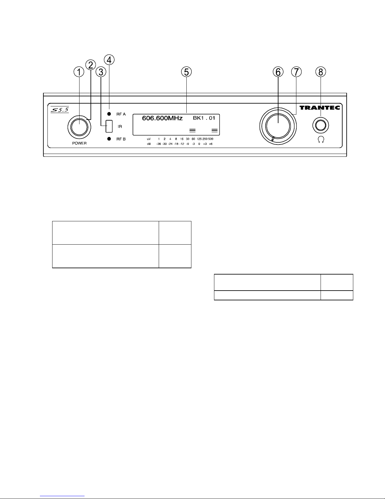
Receiver : S5.5-RXA
[Front]
1. Power switch
Press this switch to turn the power on, and press it
again to turn off the power.
2. Power indicator
Depending on the state of the power switch, the
indicator lit or unlit state will be determined as
follows.
The supplied AC adapter is
connected to the receiver, but the
power switch is turned off.
Lit (red)
The power switch is turned on with
connecting the supplied AC adapter
to the receiver.
Lit (blue)
3. Infrared (IR) port
Transmit the infrared signal for the setting of the
transmitter.
4. Reception lamps [RF A, RF B]
Either lamp of R F A or R F B lights red when
the receiver matches a radio signal from the
transmitter.
5. LCD screen
Displays the receiving status when the unit is in
normal operating state.
In setting mode, the screen displays the setting
items and their contents.
6. Jog wheel
Rotate and press this knob to change the
setting parameters or select the setting
contents on the setting screen.
7. Mute indicator
Depending on the state of reception, the
indicator lit or unlit state will be determined as
follows.
When being received normally *1 Lit
(green)
Muting condition *2 Lit (red)
*1 While receiving radio waves and when audio
output is in a ready state.
*2 While receiving radio waves, in the state
when audio output does not occur. Or when
reception does not occur.
8. Headphone output
1/4” jack socket
Mute : 5
RF A
BMUTE
6
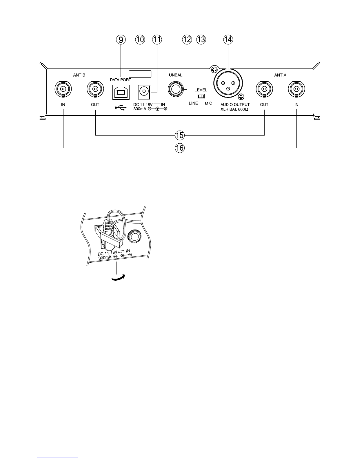
[Rear]
9. USB port
Used to connect the unit to a PC with the
installed software.
10. Cable hanger
Hook the power cable onto this part.
11. DC input jack
Connect the power cable of the supplied
AC adapter to this jack.
12. AF output
Unbalanced 1/4” jack socket, male type
+9 dBm (maximum)
13. AF output level selector
Sets the output level from the AF outputs by
selecting either MIC or LINE
14. AF output
MIC / LINE selectable, balanced, XLR
connector, male type
LINE level : +15dBm (maximum)
MIC level : -25dBm (maximum).
15. Antenna distribution outputs A, B
50 ohm, BNC
Output the same signals as those which are
input to Antenna inputs A, B. Used for an RF
cascade connection.
16. Antenna inputs A, B
50 ohm, BNC
Phantom powering for the external antenna
(optional)
For the wireless system covering a relatively
narrow area, use the supplied two rod antennas,
which should be set up at 45° outwards from
a vertical line.
7
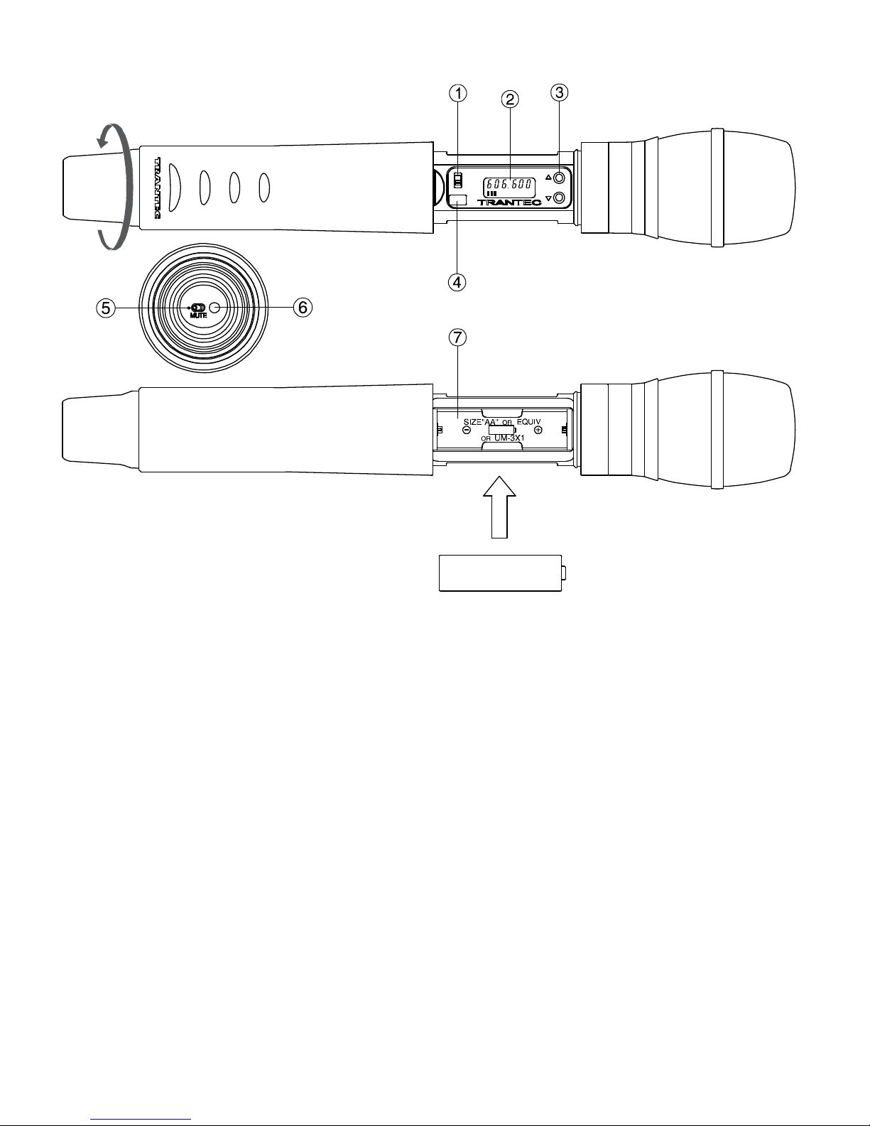
Handheld microphone : S5.5-HDX2 & S5.5-HCX2
1. Power switch
Slide this switch towards “ON” position to
turn the power on, and slide it again towards
“OFF” position to turn off the power.
2. LCD screen
Displays the state of the unit.
3. Up down key [▲▼]
Used to select the channel (frequency) and
AF gain. (The frequency must be identical to
that of the receiver.)
4. Infrared (IR) port
Receive the infrared signal from the receiver
to set-up the transmitter.
5. Muting switch
Flick this switch towards the power lamp to
mute the audio.
6. Power lamp
A blue LED lights with turning on the power
switch.
7. Battery compartment
Insert an AA battery accordi ng to (+ ) and (–)
indications on the battery compartment.
Note Turn off the power switch.
8
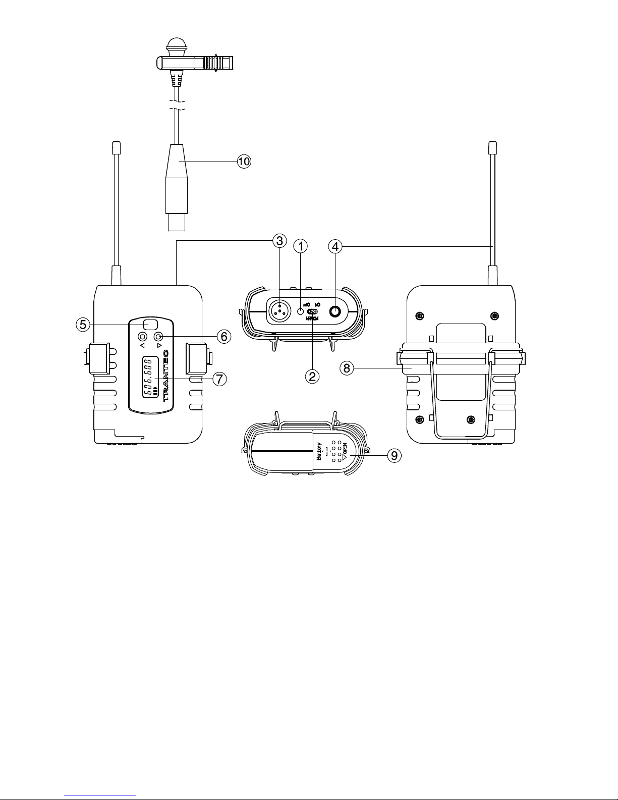
Belt-pack transmitter : S5.5-BTX2
1. Power lamp
A blue LED lights with turning on the power
switch.
2. Power switch
Slide this switch towards “ON” to turn the
power on, and slide it again towards “OFF” to
turn off the power.
3. Input connector
Mini-XLR socket, Connect the
microphone or the instrument cable.
4. Antenna
Note Never position the transmitter antenna
directly against the body or hand. This will
have the effect of reducing the operating
range considerably.Used to select the
channel (frequency). (The frequency must
be identical to that of the receiver.)
5. Infrared (IR) port
Receive the infrared signal from the receiver.
6. Up down key [▲▼]
Used to select the channel (frequency) and AF
gain. (The frequency must be identical to that of
the receiver.).
7. LCD screen
Displays the state of the unit.
8. Clip
Clip the transmitter to a belt through the
transmitter clip. It is better the belt should
be pressed against the base of the
transmitter clip.
9. Battery compartment
Insert an AA battery according to (+ )
indications on the battery door.
Note: Turn off the power switch.
10. Microphone
Note: Route the microphone cable so as to
avoid undue strain of friction. Try and keep the
microphone cable away from the antenna.
9
6. RECEIVER FREQUENCY SELECTION
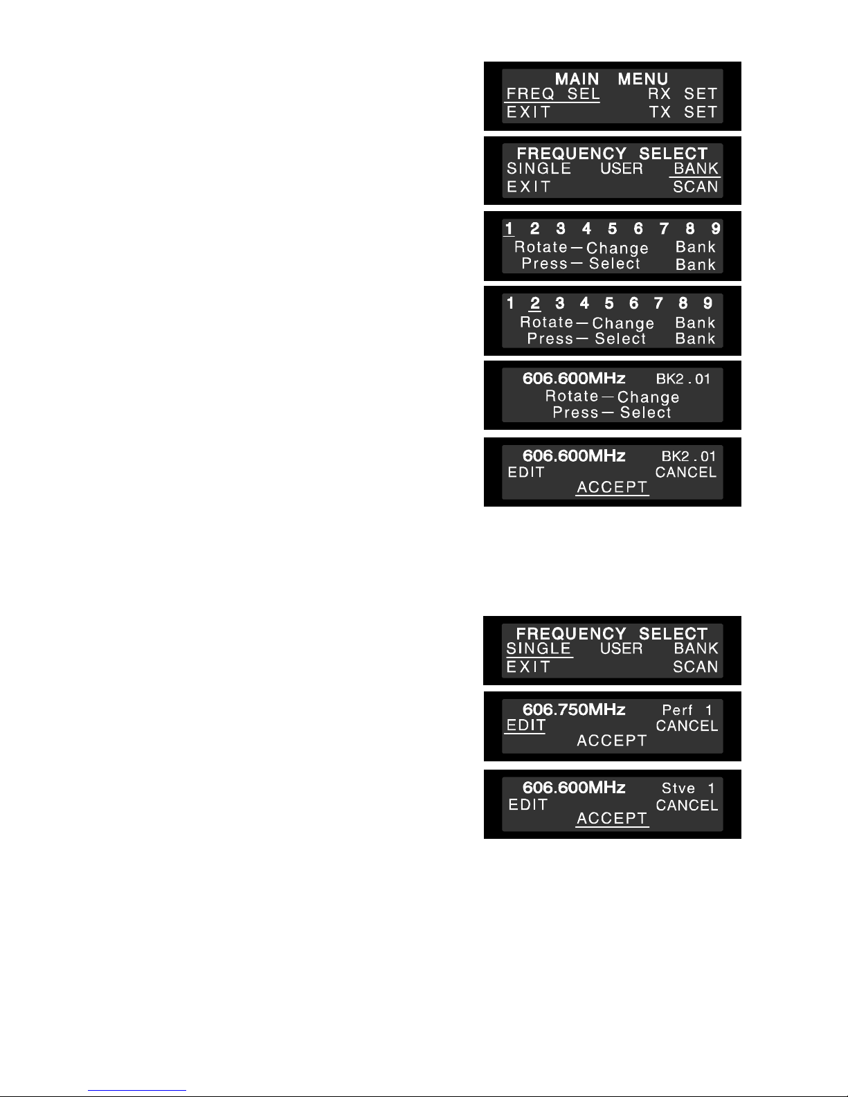
6-1. To change the selected channel in BANK
Step 1. Press and hold the “Jog-wheel” for approximately 3
seconds if the receiver is not in mute to enter the
MAIN MENU. You will enter the MAIN MENU
immediately if the receiver is in mute.
Step 2. With FREQ SEL (Frequency selection) underlined
press the “Jog Wheel”. This will give you the next
menu.
Step 3. Rotate the “Jog Wheel” untill BANK is underlined and
press to give you the Bank selection screen below
right.
Step 4. Rotate the “Jog Wheel” to underline the number of a
new bank, then press to select.
Step 5. Rotate the “Jog-wheel” to change the channel within
this bank, and press to select the frequency shown.
Step 6. Rotate and press again with ACCEPT underlined to
accept the new bank and frequency, and return to
the normal display state.
Note Make sure that the transmitter is identical to the
receiver in the channel number. Should the
microphone's setting differ from that of the receiver,
the receiver does not receive the radio signal from the
transmitter.
6-2. To change the selected channel to a Custom single frequency
Step 1. This option allows the customer to select 1 of over 1400 available channels. Press and hold the “Jog-
wheel” for approximately 3 seconds if the receiver is not in mute to enter the MAIN MENU. You will
enter the MAIN MENU immediately if the receiver is in mute.
Step 2. With FREQ SEL (Frequency selection) underlined
press the “Jog Wheel”. With SINGLE underlined press
the “Jog-wheel”.
Step 3. With EDIT underlined press the “Jog- wheel”. The first
part of the frequency will be flashing. Rotate the “Jog-
Wheel” to select this section of a new frequency and
press to accept. The second part of the frequency will
now start flashing. Change the second part of the new
frequency as above.
Step 4. You can then change each letter of the user name in
the same way. All ASCII characters are available for
the user name.
If you wish to exit this menu at any time, press and
hold the “Jog-Wheel”.
Step 5. Press the “Jog-Wheel” for 1 second to exit then rotate till ACCEPT is underlined and press to select the
new custom frequency and user name.
Note In the case of the S5.5 it will be added to the Custom USER bank. You can download USER banks via
the TRANTEC software. Please refer to the software manual on this CD for more information.
10
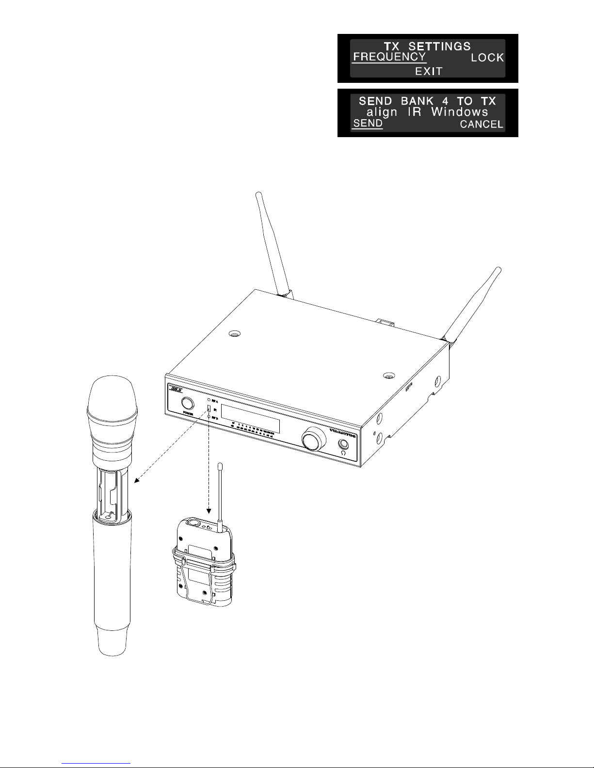
6-3. To Program a transmitter with Bank information via receiver Infrared port
Step 1. Press and hold the “Jog-wheel” for approximately 3
seconds if the receiver is not in mute to enter the
MAIN MENU. You will enter the MAIN MENU
immediately if the receiver is in mute.
Step 2. Rotate the “Jog Wheel” till TX SET is underlined and
press to enter TX SETTINGS. With FREQUENCY
underlined, press the “Jog Wheel”.
Step 3. Align the transmitter and receiver infra-red windows
with the transmitter no more than 15 cm from the
receiver. With SEND underlined, press the “Jog Wheel” and wait a few seconds. All frequencies in the
bank selected will be transferred to the transmitter and its current frequency will be set to match the
receiver’s current frequency. The receiver will return to its main display.
Note If the receiver is currently in a SINGLE or USER frequency, it will transfer the USER bank.
11
7. M ISCELLANEOUS SETTINGS ON RECEIVER
7-1. Mute/Squelch Settings
The S5 series uses sophisticated internal mute functions including Pilot Tone, Noise and RSSI to prevent noise
break through from external sources when the transmitter is in the “OFF” position. The RSSI (Received signal
strength) portion is user adjustable via the RX SETTINGS menu.
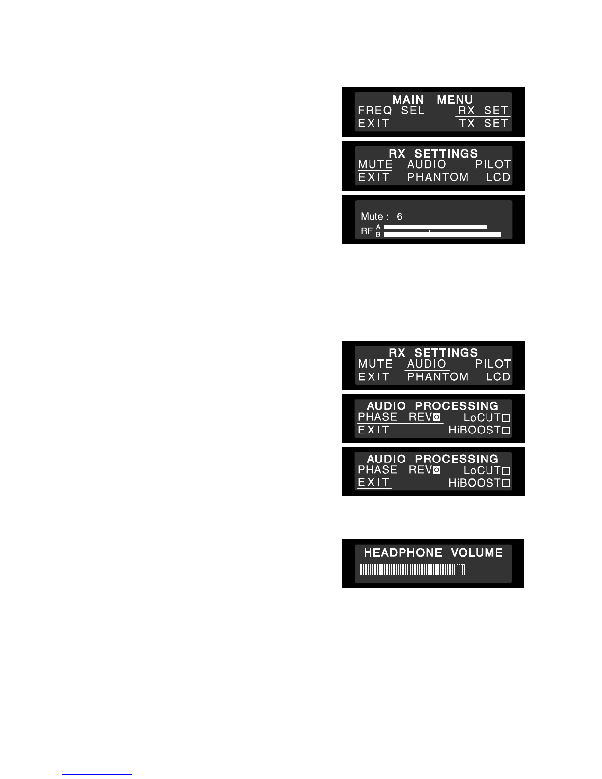
Step 1. To Access RX SETTINGS press the “Jog-Wheel” for 1
second and enter the MAIN MENU, or for 3 seconds if
not in mute.
Step 2. Rotate till RX SET is underlined and press. With
MUTE underlined, press the “Jog-Wheel”.
Step 3. Now rotate the “Jog- Wheel” to adjust the mute setting
between 1 and 10, then press. A marker shows the
current mute setting in relation to the RF A and B
scales.
Note High mute settings will decrease range and low mute
settings increase the interference potential. We
recommend a setting of 4 to 6. The mute level
changes in real time as the setting is varied.
Ensure the correct setting of the Mute for effective
control of interference whilst the transmitter is turned off. The default is normally 5 but may need to be
increased with multi-channel set-ups.
7-2. Audio Processing
Step 1. Press the “Jog-Wheel” to enter the MAIN MENU. Rotate till RX SET is underlined then press. On the
RX SETTINGS menu, rotate till AUDIO is underlined and press.
Options available in AUDIO menu are PHASE REV, LoCUT,
and HiBOOST. The default factory setting for all these options
is OFF.
PHASE REV – reverses the audio output phase.
LoCUT – reduces the low frequency response.
HiBOOST – increases the high frequency response.
Step 2. Navigate to each option by rotating the “Jog-Wheel”
and press to check the box for each option when it is
underlined. All three of the above functions change in
real time as the option is selected.
Step 3. Rotate the “Jog-Wheel” to underline EXIT after
making your selections, and press to return to the
main screen.
7-3. Headphone Volume
Step 1. Rotate the “Jog-Wheel” while the main screen is
showing to go to the headphone volume adjustment.
Step 2. A bar graph of the volume is shown and can be
altered by again turning the “Jog-Wheel”.
Step 3. Push to exit and return to the main screen. The unit
will return to the main screen automatically if there is no user intervention for approximately 2 seconds.
Any change you have made will be saved.
12
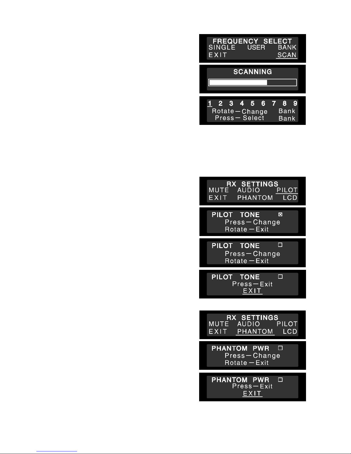
7-4. Channel Scan
The scanning feature can determine which frequencies are currently being used in the vicinity of your receiver.
Step 1. From the main screen press the “Jog- Wheel” to go to
MAIN MENU, rotate till FREQ SEL, is underlined and
push.
Step 2. Then rotate till SCAN is underlined and push. The
scanning process takes about 10 seconds and you
will then be shown the Bank selection screen. If
interference is found on a frequency during the scan,
the bank containing that frequency is made
unavailable on the receiver. You can then select any
bank from those available, and any frequencies from
within those banks.
Note Multiple System Setup
• The proper operation of your wireless system may be
interfered with by other system operating on the same
frequency. In such cases, change the operating
frequency of your system.
• Do not mix separate Banks in multi-channel set-ups.
• Use the SCAN function to check for external interference.
• Set up each system one at a time, confirm each system is assigned a different channel, and leave the
transmitter powered on. Otherwise, the channel scan from the other receiver will not detect as the occupied
channel.
7-5. Pilot Tone
The S5 series has the ability to disable the pilot tone as a
means of either identifying outside interference or allowing
compatibility with non-pilot tone devices. The default factory
setting is ON.
Step 1. To disable Pilot Tone press the “Jog- Wheel” to go to
MAIN MENU. Rotate till RX SET is underlined and
push to go to the RX SETTINGS menu.
Step 2. Rotate the “Jog-Wheel” to underline PILOT and press
to uncheck the box.
Step 3. Rotate the “Jog-Wheel” to underline EXIT, and press
to return to the main screen.
7-6. Phantom Power
DC added to the antenna inputs for powering head amplifiers.
The default factory setting is OFF.
Step 1. Push the “Jog- Wheel” to show the MAIN MENU.
Rotate the “Jog-Wheel” to underline RX SET, and
push to show the next RX SETTINGS menu.
Step 2. Rotate to underline PHANTOM, and push. Press to
check the PHANTOM PWR box.
Step 3. Rotate and then press to choose EXIT and return to
the main screen.
13
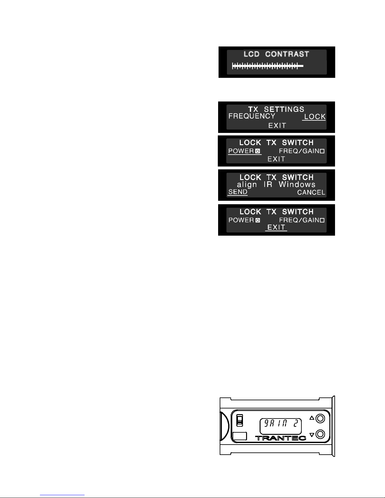
7-7. LCD Contrast
Step 1. Push the “Jog-Wheel” to bring up the MAIN MENU. Rotate the “Jog-Wheel” to underline RX SET and
push.
Step 2. Rotate to underline LCD and push, then rotate the
“Jog-Wheel” to alter the LCD CONTRAST.
Step 3. Push to exit and return to the main screen. The unit
will return to the main screen automatically if there is
no user intervention for approximately 2 seconds. Any
change you have made will be saved.
7-8. Lock TX switch
To prevent unauthorised or accidental changes of frequency
or gain on a transmitter, or accidentally turning a transmitter
off during a performance you can lock these features from the
receiver.
Step 1. Press the “Jog-Wheel” to show the MAIN MENU.
Rotate the “Jog-Wheel” to underline TX SET and
push to select this option.
Step 2. Rotate the “Jog-Wheel” till LOCK is underlined and
push to select this. Push the “Jog-Wheel” to check the
box for POWER if required, or rotate to go to
FREQ/GAIN and push to check this box if required.
Step 3. Rotate till EXIT is underlined and push. You will then
have the option to SEND the TX Locks you have
selected, to a transmitter or CANCEL. If you are
sending Locks to a transmitter you should hold it
within 15cm of the receiver and with the infra-red
windows of each aligned.
8. HANDHELD MICROPHONE SET-UP
Step 1. O p e n i n g t h e m i c r o p h o n e
Undo the handheld sleeve by unscrewing the end cap at the base anti- clockwise and then gently sliding
the sleeve down to expose the LCD and Battery compartment.
Step 2. B a t t e r y f i t t i n g
Place an Alkaline “AA” cell into the battery compartment noting the correct polarity as shown on the
label in the compartment.
Step 3. S w i t c h o n
Slide the On/Off switch to the “On” position and observe the display is on and the Power On LED
located in the end cap is illuminated.
Step 4. C h e c k f o r r e c e i v e d s i g n a l
Check that the display indicates the same channel as the receiver. The receiver should now show a
received signal on its RF bar graphs and after 20 seconds the transmitter battery status.
Step 5. F r e q u e n c y a d j u s t m e n t
Turn on the transmitter and adjust the frequency whilst the “decimal point” is flashing (approx. 6 secs)
via the “Up” or “Down” buttons. When the correct
frequency is selected, turn the transmitter off then on
again to activate the newly selected channel.
Step 6. G a i n a d j u s t m e n t
Turn on the transmitter and wait for the flashing
“decimal point” on the LCD to stop flashing. Press the
“Up” or “Down” buttons to increase or decrease the
head sensitivity. The display will show 0 -5, with “0”
gain being for max SPL.
14
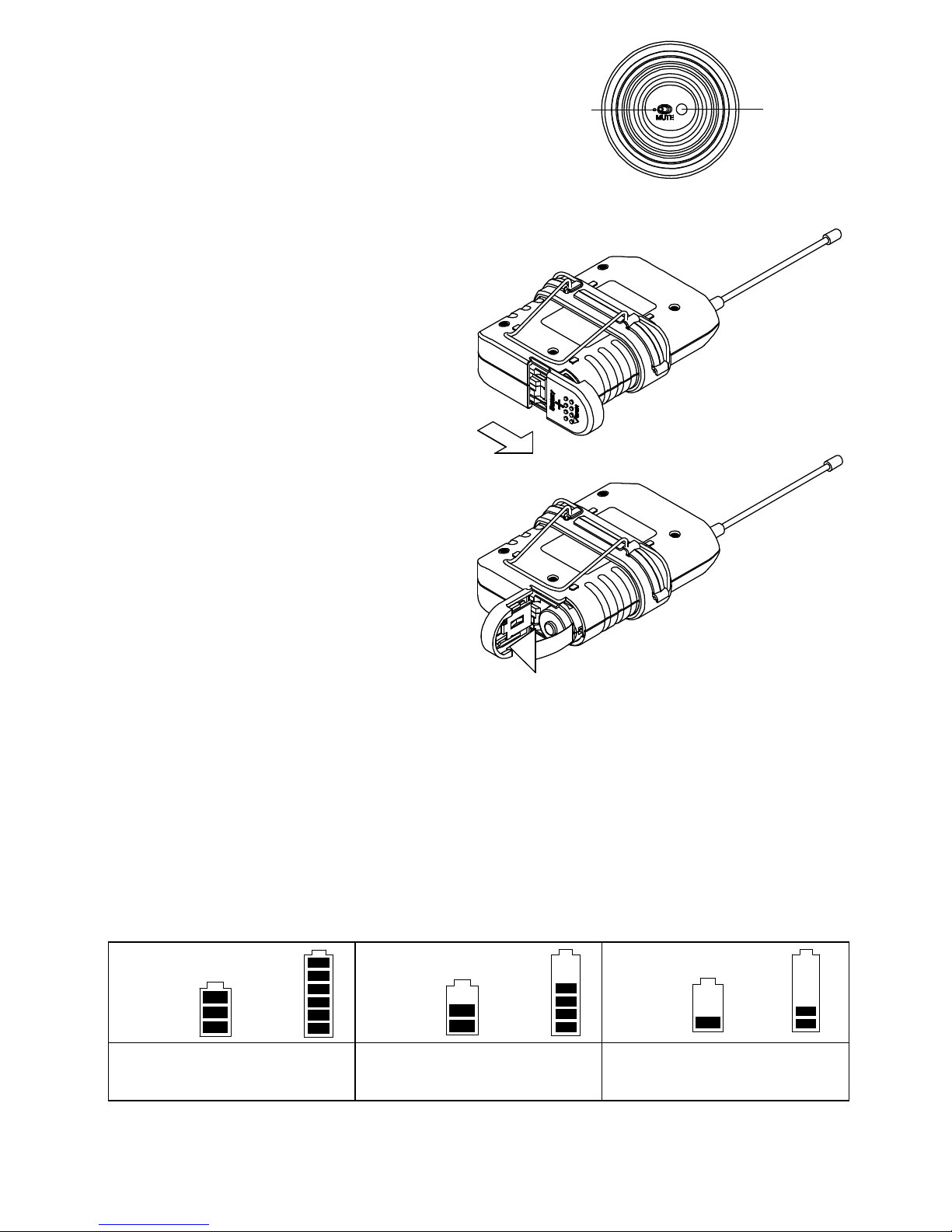
Step 7. M u t e s w i t c h
Incorporated in the handheld end cap is a Power On
LED and Audio Mute switch. To mute the audio, flick the
switch towards the LED.
Turn on Audio Mute swithch, Power On LED blinks.
Turn on Power Switch with audio muting, after
Power On LED lights for 30 sec, starts blinking.
9. BELTPACK TRANSMITTER SET-UP
Step 1. B a t t e r y f i t t i n g
Open the battery compartment by sliding the
door forward and up. Insert a battery
observing the correct polarity as shown. The
door is marked with a “Battery +”.
Step 2. A n t e n n a f i t t i n g
Screw the antenna into the antenna bush.
Step 3. M i c r o p h o n e
Plug a mic into the Mini-XLR socket.
Step 4. S w i t c h o n
Flick the On/Off switch to the “On” position
and observe the display is on and the
battery LED illuminated. Check the display
indicates the same channel as the receiver.
Step 5. C h e c k f o r r e c e i v e d s i g n a l
Check that the display indicates the same
channel as the receiver. The receiver should
now show a received signal on its RF bar
graphs and after 20 seconds the transmitter
battery status.
Step 6. F r e q u e n c y a d j u s t m e n t
Turn on the transmitter and adjust the
frequency whilst the “decimal point” is flashing (approx. 6 secs) via the “Up” or “Down” buttons. When
the correct frequency is selected, turn the transmitter off then on again to activate the newly selected
channel.
Step 7. G a i n a d j u s t m e n t
Turn on the transmitter and wait for the flashing “decimal point” on the LCD to stop flashing. Press the
“Up” or “Down” buttons to increase or decrease the AF gain. The display will show 0 -9, with “0” gain
being for minimum.
10.
BATTERY INDICATON
When the battery capacity in the corresponding transmitter becomes low, the display of the LCD on the
receiver and the transmitter indicate the transmitter’s remaining battery capacity. Replace the transmitter
battery.
Transmitter Receiver Transmitter Receiver Transmitter Receiver
Battery capacity is full. Battery capacity depletion has
started.
Battery capacity is almost
depleted, and battery
replacement is required.
Power
lamp
Mute
switch
15
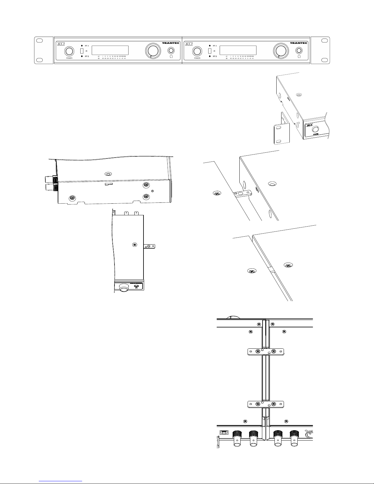
11.
S5 Series Rack Mount Kit
11-1. 19” Rack Mounting for 2 x S5 Series Receivers
The rack mounting kit is supplied as standard with S5.5 systems.
Step 1.
Unscrew the front 3 lid retaining screws from opposite sides of each receiver
case and fit the angled rack brackets, using the supplied screws. There are 3
of these supplied with each receiver.
Step 2.
Remove the 2 plastic plugs from the top of the receiver lid and fit a metal
joining strip (2 supplied per receiver) in the slots at the side of each lid of the 2
receivers. Carefully fit the M3x6 screws (1 supplied with each receiver, colored
black).
Step 3.
Fit 2 joining strips across the bottom of the receiver
chassis using 4 M3x6 CSK screws (2 supplied per
receiver).
16
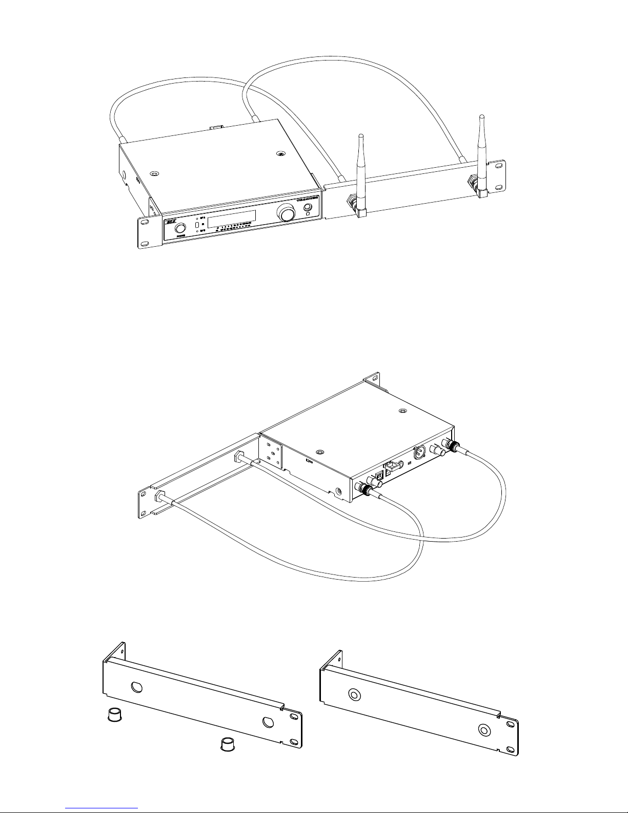
11-2. 19” Rack 1 x S5 Series Receiver with Front Mount Antenna
The rack mounting kit is supplied as standard with S5.5 systems.
Step 1.
Unscrew 3 x lid retaining screws (M3x6) from the front left side of the chassis (viewed from the front)
and fit the small angled rack bracket, using the supplied screws. There are 3 of these supplied with
each receiver.
Step 2.
Unscrew 3 x lid retaining screws (M3x6) from the front right side of the chassis and fit the supplied long
angled bracket using the screws supplied.
Step 3.
Fit the 2 supplied antenna extension cables into the front panel long bracket and tighten their BNC nuts.
Screw the BNC plugs of each into the antenna sockets on the rear of the receiver. Should front mount
antennae not be required, fit the 2 plastic blanking plugs supplied into the spare holes.
17
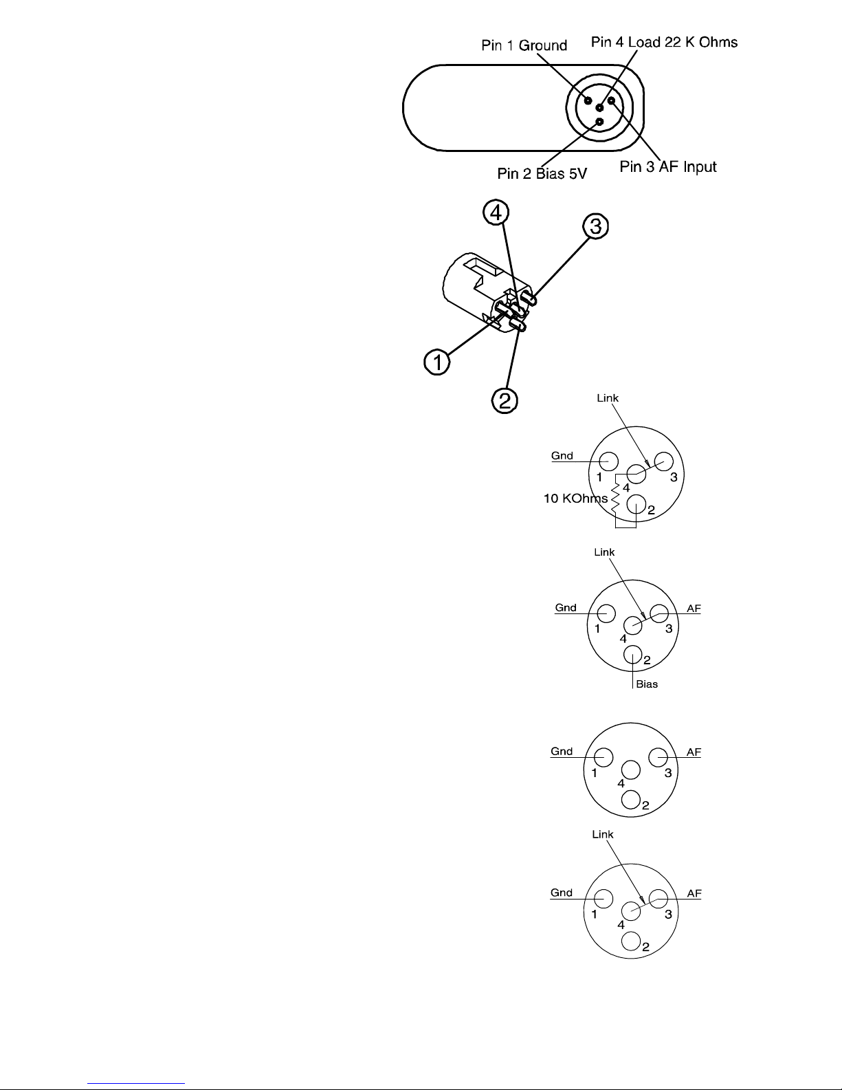
12.
Mini-XLR Wiring Connections
Beltpack Audio Mini-XLR Connections
1. Ground
2. Bias 5 V
3. AF Hi-Z
4. AF Load Resistor
Solder connections for Mini-XLR flying socket
12-1. Wiring for Mini-XLR Flying Socket
2 Wire Mic
Pin 1: Ground Pin 2: 5 V
Pin 3: AF
Pin 4: Internal AF load resistor
Link pins 3 and 4 and add a 10 KΩ bias resistor as illustrated
3 Wire Mic
Pin 1: Ground Pin 2: 5 V
Pin 3: AF
Pin 4: Internal AF load resistor
Link pins 3 and 4 as illustrated
Hi Impedance Guitar/Instrument
Pin 1: Ground
Pin 2: 5 V - Not connected
Pin 3: AF Hi Z
Pin 4: Not connected
Connect screened cable to pin 1 ground and pin 3 AF Hi-Z
Lo Impedance Microphone (No Phantom)
Pin 1: Ground
Pin 2: 5 V - Not connected
Pin 3: AF Hi-Z
Pin 4: Internal AF load resistor
Link pins 3 and 4 and connect screened cable to pin 1 ground and pins 3 and 4 as illustrated

18
13.
OPERATIONAL HINTS
• When the transmitter user moves in a facility, signal dropouts (momentary losses of signal reception) may
be encountered. These dropouts are caused by the building's architectural designs or materials which block
the travel of or reflect the radio signal. If this occurs, the user needs to change locations for better signal
reception.
• Confirm the good line of sight between the transmitter and the receiver. Do not place the large obstructions
(ex. Concrete walls or large metal obstructions) between the transmitter and the receiver. In addition keep
the receiver away from the metallic beams and obstructions as these can adversely affect the antenna pick-
up pattern and induce the interference.
• Set the transmitter AF gain so the receiver VU indicates 0 db with occasional peaks to +6 dB.
• Hold the microphone within 20cm from the sound source. Move the microphone closer for a warmer sound
increased. And do not cover the grille with hand.
• Keep your mouth 15 – 20 cm away from the lavalier microphone for the best possible sound reproduction. In
case of the Omni-directional response, it will pick up sounds from all directions. It is better that the
microphone is placed closer to the sound source. Take care not to bring your mouth too close to the
microphone (within 5 cm) as this impairs speech clarity if you speak loudly.
• In case of the headset microphone, by adjusting the gooseneck, locate the microphone with the supplied
windscreen in front of your mouth, and position it 3 – 5 cm away from your mouth for the best sound
reproduction. When the microphone is too close to your mouth or you speak too loud, speech clarity will be
impaired, making it hard for the audience to hear announcements.
14.
TROUBLESHOOTING
Issue Condition Solution
No operation of Transmitter Check the capacity of the
battery
Replace the current battery with
a fresh one of the correct
Alkaline “AA” type.
No RF signal on receiver Receiver Reception lamps
[either A or B] , mute indicator ,
and RF signal level meter do not
light.
Check the transmitter and
receiver are “Tuned” to the same
channel.
No sound Receiver Reception lamps
[either A or B] or RF signal level
meter lights.
Confirm the connections of all
sound system or gain.
Sound distorted VU bar graph on the receiver
shows too high.
Confirm the transmitter gain.
Reduce the gain of the
transmitter if the VU meter shows
over 6dB.
Confirm the receiver XLR mic-
line switch for a correct match to
your Mixer/Amplifier.
AF Signal low level with high
background noise
VU bar graph on the receiver
shows low.
Adjust the transmitter gain so the
VU bar graph shows 0dB with
6dB peaks.
External Head amplifiers not
operating
Receiver Reception lamps
[either A or B] , mute indicator ,
and RF signal level meter do not
light.
Check for shorts in the leads and
ensure the receiver PHANTOM
PWR is switched on via the RX
SETTINGS menu.
Receiver LCD contrast poor Check the LCD contrast. Enter the receiver RX
SETTINGS menu, select LCD
and press then rotate the “Jog-
Wheel” to adjust the contrast.

19
Poor range or sound dropouts Receiver Reception lamps [A
and B] are flicking or RF signal
level meter turn light off..
The system must be set up
within recommended range.
The transmitter must be used in
line of sight from the receiver.
Check the channel scan, confirm
nearby source of interference,
and change the receiver and the
transmitter to a different channel.
Check the mute level setting. For
normal range we recommend a
mute setting of 4-6.
Confirm the battery indication,
and replace the transmitter
battery.
15.
CERTIFICATIONS
In compliance with
RED:
EN 301 489-1 V2.2.0 (2017-03)
EN 301 489-9 V2.1.1 (2017-03)
EN 300 422-1 V2.1.2 (2017-01)
EN 62368-1: 2014+A11: 2017
RoHS:
EN 50581: 2012
CE Declaration of Conformity
2014/53/EU RED
2011/65/EU RoHS
Traceability Information for Europe
Manufacturer:
TOA Corporation
7-2-1, Minatojima-Nakamachi, Chuo-ku, Kobe,
Hyogo, Japan
Authorized representative:
TOA Electronics Europe GmbH
Suederstrasse 282, 20537 Hamburg, Germany
URL: www.toa.de

20
16.
SPECIFICATIONS
System
Modulation Wideband FM
Frequency Range UHF band (606-638 MHz), 10 banks x 24 channels (max.)
RF switching band width 36 MHz typ.
Tunable Frequencies 25 kHz Steps
Pilot tone 32.768kHz
Total Harmonic Distortion < 0.8 % @1kHz deviation 22 kHz
Function IR sync, Channel scan, Battery life information
Dynamic Range >110 dB(A)
Operating Temperature Range -10°C to +50° C
TRANSMITTER
S5.5-HDX2, S5.5-HCX2 S5.5-BTX2
Microphone unit
Dynamic with cardioid pattern (HDX)
Electret condenser with cardioid pattern
(HCX)
TRANTEC series lavalier and head set
microphone
RF Carrier Power 10 mW 10 mW
Audio Frequency
Response
100 - 12000 Hz (HDX)
200 - 16000 Hz (HCX) 50 - 18000 Hz
Audio input Level 140 dBSPL (maximum) -6dBV (maximum), mic gain 0dB
Battery Life approx. 8 hours approx. 8 hours
Power Supply 1 AA size alkaline battery, 1.5 V 1 AA size alkaline battery, 1.5 V
Finish Body : Aluminium, black, paint
Microphone head : Steel, black, paint Aluminium, black, paint
Dimensions* φ48 x 245 mm 55 (W) x 80 (H) x 22 (D) mm (with clip)
Weight* (HDX) 305 g (with battery)
(HCX) 275 g (with battery) 105 g (with battery)
RECEIVER
S5.5-RXA
Diversity Reception Dual Diversity featuring PLL Dual Double conversion receivers
Sensitivity 1uV at 12 dB SINAD
Squelch (SQ) Tone SQ, Carrier SQ, Noise SQ
Carrier SQ range 10 steps 30 dB
Antenna Inputs BNC 50 ohm (phantom powering for antenna) 9 V DC, 60 mA
short-circuit protected on each RF port
Antenna Outputs BNC 50 ohm (Gain 0 dB)
Audio Frequency Response 50 - 20000 Hz
Audio Output Level
(Maximum)
Balanced (XLR socket) LINE level : +15 dBm
MIC level : -25 dBm
Un-balanced (1/4" jack socket) : 9 dBm
Power Supply 12 VDC 300 mA
Dimensions* 210 (W) x 46 (H) x 210 (D) mm (excluding antenna)
Weight* 1.3 kg
0dBu=0.775V
Note: The design and specifications are subject to change without notice for improvement.
• Accessory
Microphone holder (For handheld microphone)
Color rings (6 colors) (For handheld microphone)
133-07-00106-00
Table of contents
Other Trantec Microphone System manuals


