Ritron MOBILE RADIO User manual

page 1
RITRON MOBILE RADIO
INSTALLATION GUIDE
Pub. No. 01454928 REV. E 02
—
02
PREPARATION
Important: THE RITRON MOBILE CAN BE OPERATED ONLY IN
NEGATIVE GROUND ELECTRICAL SYSTEMS! A negative ground system
has the negative (
—
) battery terminal connected to the vehicle motor block. If
you cannot find this connection, consult the vehicle owner's manual to
determine the ground system type. Most late model U.S. and foreign made
cars and small trucks use a negative ground electrical system. However, some
older cars and newer large trucks use a positive ground system.
MOBILE RADIO PACKAGE CONTENTS
Make sure that all of the items listed below are included in the radio package,
which holds a mobile transceiver and two boxes of equal size. One box contains
the microphone and attached cord. The other includes hardware for installing:
1) the DC power cable; 2) the mobile radio and 3) the microphone hang-up clip.
• DC POWER CABLE
Parts for power cable installation: 10-foot DC cable with attached fuse holder
assembly (1); 10 A fuse (1); 20 A fuse (1); ring lug (2); plastic tie (2).
• MOBILE RADIO
Parts for radio installation: radio mounting bracket (1); Phillips head sheet
metal screw #10 x 3/4" (4); lock washer (4); flat washer (4); slotted head
washer hex nut screw #10-32 x 5/8" (2); rubber washer 11/8" DIA. (2).
• MICROPHONE HANG-UP CLIP
Parts for hang-up clip installation: microphone hang-up clip (1); Phillips
head self-tapping screw #6 x 3/8" (2).
RECOMMENDED TOOLS
• PHILLIPS #2 SCREWDRIVER • 19/32" DIAMETER DRILL BIT
• TORX SCREWDRIVER, T25 • 9/64" DIAMETER DRILL BIT
• 5/16" HEX NUT DRIVER • 7/64" DIAMETER DRILL BIT
• CENTER PUNCH • WIRE CUTS
• HAMMER • CRIMPING TOOL
• ELECTRIC DRILL
MOUNTING LOCATIONS
Before you begin installation, inspect the vehicle and decide how and where
to mount the antenna, radio and microphone. Plan wire and cable runs to
provide maximum protection from pinching and crushing.
• ANTENNA
Permanent Mount: The best place to mount the antenna is in the center of
a large, flat conductive surface, such as the vehicle's roof. A large trunk lid
also provides a good antenna location. If you use the trunk lid, connect
grounding straps between the trunk lid and vehicle chassis. See the
antenna installation instructions for complete directions.
Glass Mount: Position a glass-mounted antenna as high as possible in the
center of the rear window or windshield. Consult the antenna installation
guide for further instructions.
Magnet Mount: The magnet mounted antenna should be attached to the
center of the vehicle's roof or trunk lid. If you use the trunk lid, connect
grounding straps between the lid and vehicle chassis! Refer to the antenna
installation sheet for details.
• RADIO MOUNTING BRACKET
The radio mounting bracket permits attaching the mobile to a variety of
surfaces, and requires a flat mounting surface (6" x 2" minimum) with
adequate clearance for inserting the radio. Be certain the mounting surface
can support the radio's weight. Leave enough space around the radio for
air flow cooling, and make sure the user can easily reach and view the
mobile's operating controls and access rear panel connections. The
mounting bracket and radio must not impair vehicle operation. Although the
bracket can be fixed to a plastic dashboard, the mounting screws should
penetrate into the dashboard's supporting metal frame.
• MICROPHONE HANG-UP CLIP
The microphone clip may be attached to any metal or plastic surface strong
enough to withstand continued microphone use; a hang-up clip to ground
connection is not required.
page 2
• MICROPHONE HANG-UP CLIP (continued)
Mount the clip within easy reach of the driver, mindful that using the
microphone must not impair vehicle operation. Although the hang-up clip
can be mounted to a plastic dash board, the mounting screws should
penetrate into the dash board's supporting metal frame.
PROCEDURE
FAILURE TO COMPLY WITH THE WARNING, CAUTION AND IMPORTANT
STATEMENTS ON THE FOLLOWING PAGES COULD RESULT IN
DAMAGE TO THE RADIO THAT WILL VOID THE WARRANTY!
DC POWER CABLE
Warning: THE RITRON MOBILE CAN BE OPERATED ONLY IN NEGATIVE
GROUND ELECTRICAL SYSTEMS! DO NOT CONNECT THE RADIO TO
THE POWER CABLE UNTIL INSTALLATION IS COMPLETE.
TO INSTALL THE POWER CABLE, FOLLOW THE STEPS BELOW:
1) Inspect the vehicle and determine how and where to run the power cable to
provide maximum protection from pinching, crushing and excessive heat.
2) Drill a 19/32" hole (or use an existing, empty hole) in the driver's side of the
firewall for passing the power cable into the engine compartment. A rubber
grommet (not provided) may be installed in the access hole to help protect
the cable. Be careful not to damage existing vehicle wires.
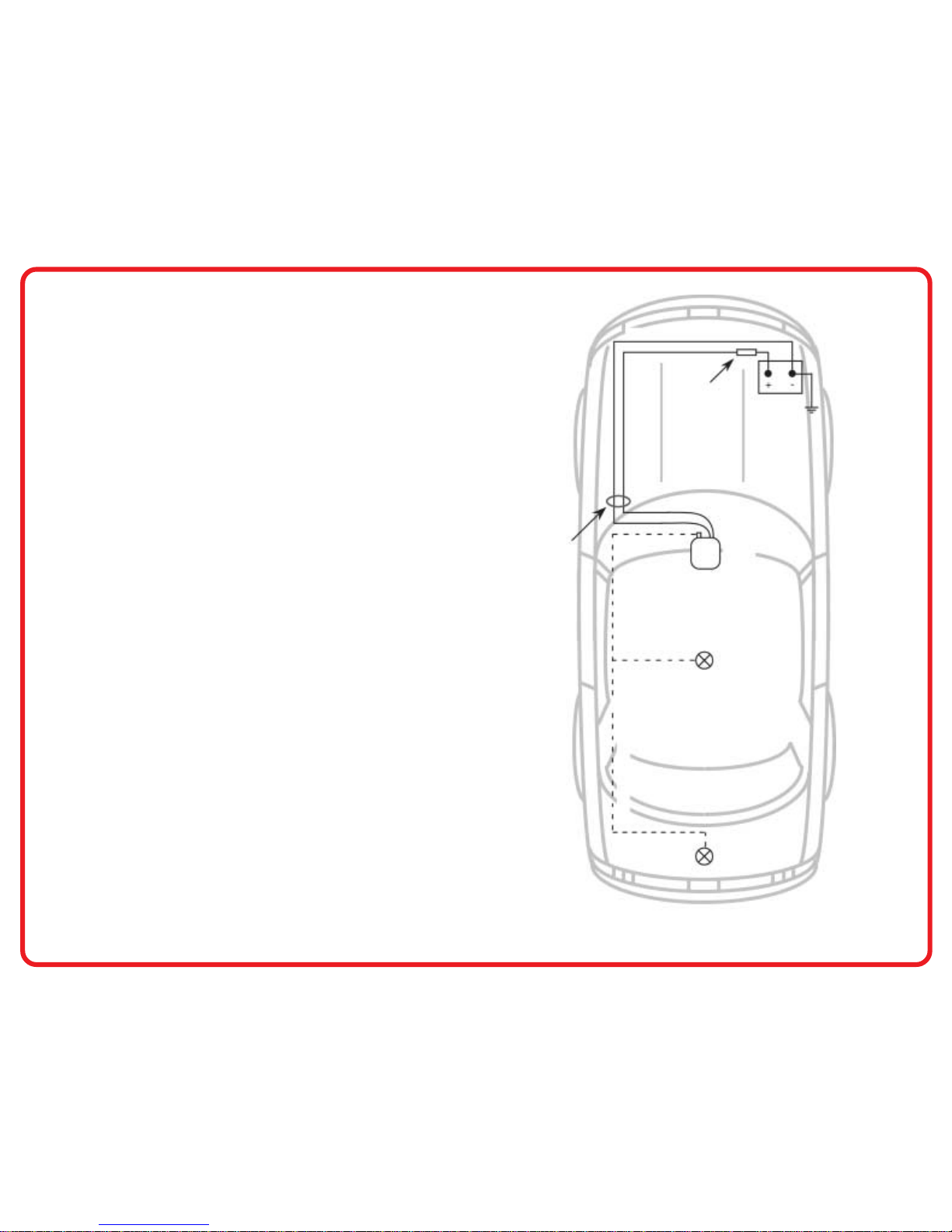
3) From inside the vehicle, feed the cable leads and fuse assembly through
the access hole and into the engine compartment. Refer to FIG-1 at right.
Leave as much space as possible between the power cable and the vehicle's
wiring (the power cable red and black wires may be twisted together).
4) Route the power cable through the engine compartment to the battery. If
the battery is located on the passenger's side, the cable should cross the
compartment in front of the engine as shown in FIG-1. If the battery is
located on the driver's side, run the cable straight to the battery. Install the
cable as far as possible from the vehicle's electronic modules and wiring.
5) Install one ring lug onto the fuse assembly lead, the other lug onto the
power cable black lead (stripped end).
6) Place the fuse assembly close to the battery, away from heat-generating
engine components. Mount the fuse assembly using the plastic ties provided.
FIG
-
1: RADIO INSTALLATION OVERVIEW
TRUNK LID
ANTENNA
LOCATION
ROOF ANTENNA LOCATION
RADIO
RED
BLACK
BATTERY
FUSE
ASSEMBLY
POWER CABLEANTENNA COAXIAL CABLE
ACCESS
HOLE IN
DRIVER'S
SIDE
FIREWALL
DC POWER CABLE (continued)
7) Connect the power cable black lead (with ring lug attached) to the vehicle's
negative (-) battery terminal, or to the jump start block on vehicles so
equipped.
Caution: Avoid disconnecting the battery-to-engine block ground, which
mightdamagethevehicleand/orradio.Anin-linefuse(notincluded)maybe
installed near the battery in the black lead. Use a 10 A fuse for RPM-150 or
RPM-450 installations, a 20 A fuse for the RPM-050.
8) Connectthefuseassemblylead(ringlugattached)tothepositive(+)battery
terminal. Check that the fuse assembly contains a fuse. Use a 10 A fuse for
RPM-150orRPM-450installationsonly.DONOTusea10AfuseforRPM-050
installations.Instead, use a 20 Ampere fuse.
Important: Failuretoconnectthepowercableredleaddirectlytothebattery
(via the fuse) can produce severe alternator noise in the radio.
ANTENNA
Mount the antenna according to the instructions included with the antenna kit.
Avoid routing the antenna coaxial cable near vehicle wiring.
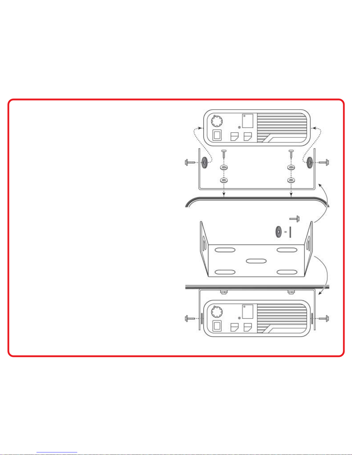
RADIO MOUNTING BRACKET
TO INSTALL THE RADIO BRACKET, FOLLOW THE PROCEDURE BELOW:
1) Selecta mountinglocation foryour radio,eitheron thetransmission humpor
under the dash. See FIG-2 at right.
2) Usingthebracketasatemplate,markdrillingpointsonthemountingsurface.
3) Centerpunch the marks you have made and drill a 9/64" hole at each.
4) Secure the bracket to the mounting surface with the #10 Phillips head sheet
metal screws (4), lock washers (4) and flat washers (4) supplied.
NOTE: Securing the radio mounting bracket with only two screws may be
sufficient.
5) Placetheradioin themounting bracketand attachit withthe rubberwashers
(2) and #10 hex nut screws (2) provided (refer to FIG-2).
page 3
FIG
-
2: RADIO MOUNTING HARDWARE
PHILLIPS HEAD SCREW
SHEET METAL #10 X 3/4"
#10 LOCK WASHER
#10 FLAT WASHER
TRANSMISSION HUMP
SLOTTED HEAD WASHER HEX NUT SCREW
#10-32 X 5/8"
RUBBER WASHER 11/8" DIA.
MOUNTING BRACKET
BASE
UNDER DASH

page 4
MICROPHONE HANG-UP CLIP
TO INSTALL THE HANG-UP CLIP, SEE THE STEPS BELOW:
1) Select a mounting location for the microphone hang-up clip, within easy reach
of the mobile radio user.
2) Using the clip as a template, mark drilling hole positions on the mounting
surface.
3) Centerpunch the marks you have made and drill a 7/64" hole at each.
4) Secure the clip with the #6 Phillips head self-tapping screws (2) provided.
5) Hang-up the radio microphone in its clip as shown in FIG-3.
FIG
-
3: MICROPHONE HANG-UP CLIP
FIG
-
4: REAR PANEL CONNECTIONS
FINAL CONNECTIONS
1) Fasten the antenna cable connector to the mobile rear panel antenna
connector. See FIG-4.
2) Plug the microphone cord into the radio front panel connector.
3) Plug the power cable into the radio back panel power connector.
(Note: newer production models are equipped with a pigtail connector.)
THE MOBILE RADIO IS NOW READY FOR OPERATION !
SAFETY PRECAUTIONS
VEHICLE OPERATION
Check the vehicle’s service manual for possible warnings about operating a
two-way radio in a vehicle equipped with an electronic anti-skid braking or ignition
system.
LIQUEFIED PETROLEUM (LP) GAS FUEL SYSTEM
Radio installation in a vehicle fueled by liquefied petroleum (LP) gas (with the LP
gas container stored in a sealed-off space, such as the trunk) must conform to
NFPA (National Fire Protection Association) standard 58.
ACCESSORY
(OPTIONAL)
ANTENNAEXTERNAL
SPEAKER
POWER
HANG-UP
MICROPHONE
IN CLIP SLOT
CLIP
PHILLIPS HEAD SCREW
SELF-TAPPING #6 X 3/8"
MOUNTING SURFACE
RITRON, Inc.
505 West Carmel Drive · Carmel, IN 46032
PH: 317-846-1201 · FX: 317-846-4978
Email: [email protected]
www.ritron.com
© 2002-1998 Ritron, Inc. All rights reserved.
Specifications subject to change without notice. Ritron is a registered trademark of Ritron, Inc.
Other Ritron Radio manuals

Ritron
Ritron QUICK TQLK Instructions for use

Ritron
Ritron Jobcom JBC-100 User manual

Ritron
Ritron RCCR User manual

Ritron
Ritron SLX Series User manual

Ritron
Ritron RF320 Series User manual

Ritron
Ritron RPM 60 Series User manual

Ritron
Ritron SLX Series User manual

Ritron
Ritron RPM 60 Series User manual

Ritron
Ritron RBS-477DMR User manual

Ritron
Ritron RPM 60 Series User manual


