Traxon Technologies ecue e:bus Reference manual

e:bus
Introduction Manual
Edition:
28.07.23 [EN_ebus_manual_v3p0]
Published by:
Traxon Technologies Europe GmbH
Karl-Schurz-Strasse 38
33100 Paderborn, Germany
©2023 Traxon Technologies Europe GmbH
All rights reserved
Read the e:bus Introduction Manual and the Safety Instructions
carefully. Subject to modication without prior notice.
Typographical and other errors do not justify any claim for
damages. Modication of the product is prohibited.
This manual is designed for electricians, system administrators,
and product users.
All product names and trademarks mentioned in this manual are
trademarks of their respective owners.
Except for internal use, relinquishment of the instructions to a
third party, duplication in any type or form - also extracts - as
well as exploitation and / or communication of the contents is not
permitted.
Traxon Technologies Europe GmbH
Sales Operations
Karl-Schurz-Str. 38
33100 Paderborn, Germany
+49 5251 54648-0
Downloads and more information at:
www.ecue.com
WWW.TRAXON-ECUE.COM ©2023 traxon technologies. All rights reserved. e:bus Introduction Manual 07/23 Sheet: 02 / 07
Table of Contents
1 Introduction 03
1.1 Advantages of the e:bus system 03
1.2 General information 03
2 Topologies 04
2.1 Wiring 04
2.2 Invalidcongurations 05
3 Cable types and lengths 05
3.1 Cabletypes 05
3.2 General run lengths 06
4 Special cabling conditions 06
4.1 Glass Touch 06
5 e:bus, DALI and DMX 06
5.1 DALI 06
5.2 DMX 06
5.3 Comparison 06
IntroductionManual—e:busIntroductionManual

WWW.TRAXON-ECUE.COM ©2023 traxon technologies. All rights reserved. e:bus Introduction Manual 07/23 Sheet: 03 / 07
1 Introduction
This document gives a short introduction to the e:bus system. e:bus is a bus system developed by Traxon
e:cue for secure, bi-directional and fast system link between e:bus enabled user terminals.
1.1 Advantages of the e:bus system
Thee:busnetworkingplatformoersseveralfeaturesforasimpleinstallationandgreatreliabilityinreal
installations.
ye:busisaself-organizingnetwork.Thissimpliescongurationbyaplug&play-likebehaviour.The
addressing happens automatically.
yLinkpower.Userinterfacesaredirectlypoweredovere:bus.Fewerwiresmakethehardware
installation much easier.
yThe connections are a very reliable and a stable communication basis with polarity-insensitive wiring.
At the end of this document (see page 06),youcanndashortcomparisonofe:buswithDALIandDMX
based communication.
1.2 General information
yUptoeightdevicescanbeconnectedtothee:bus,organizedbyasignlemasterdevice.
yFreetopologyarchitectureallowsthedevicestobeconnectedincombinationofstar,busandtree
structures.
ye:bus is designed for cable lengths of up to 400 meters, depending on cable type, topology and number
of connected devices. A bus topology allows the largest cable length.
yThe maximum stub length is 30 cm.
yInterfaces are powered via e:bus.
yInterfaces will be automatically registered and addressed.
yDefectiveunitswillnotaectthecommunicationbetweenotherdevices.
yAmaximumofeighte:busdevices,e.g.e:cueGlassTouches,issupportedbyoneSYMPLe:busNode.
!
e:bus network communication cables should be seperated
fromhighvoltagepowercables.Followlocalelectricalcodes
with regard to cable placement.
IntroductionManual—e:busIntroductionManual| Introduction
content

WWW.TRAXON-ECUE.COM ©2023 traxon technologies. All rights reserved. e:bus Introduction Manual 07/23 Sheet: 04 / 07
2 Topologies
Bus topology
SYMPL e:bus Node
Freetopology
SYMPL e:bus Node
2.1 Wiring
The e:bus is a 2-wire-bus system using screw terminal connectors to attach the wires safely and robust. The
wiringbetweenthedevicesisextremelyexible.Inadditiontothefreetopologydesign,youdonotneedtopay
attention to polarities. As long as the two e:bus connectors of a user terminal are connected to the master
unit’sconnectors,regardlessifacablegoesfrom+to+orfrom+to-,everythingwillworkne.Thetwoe:bus
connectors of a user terminal can be connected to the master unit‘s connectors either way. The terminal
deviceswillrecognizethepolarityontheirownandcongurethemselvestheproperway.
IntroductionManual—e:busIntroductionManual| Topologies
content
WWW.TRAXON-ECUE.COM ©2023 traxon technologies. All rights reserved. e:bus Introduction Manual 07/23 Sheet:05/07
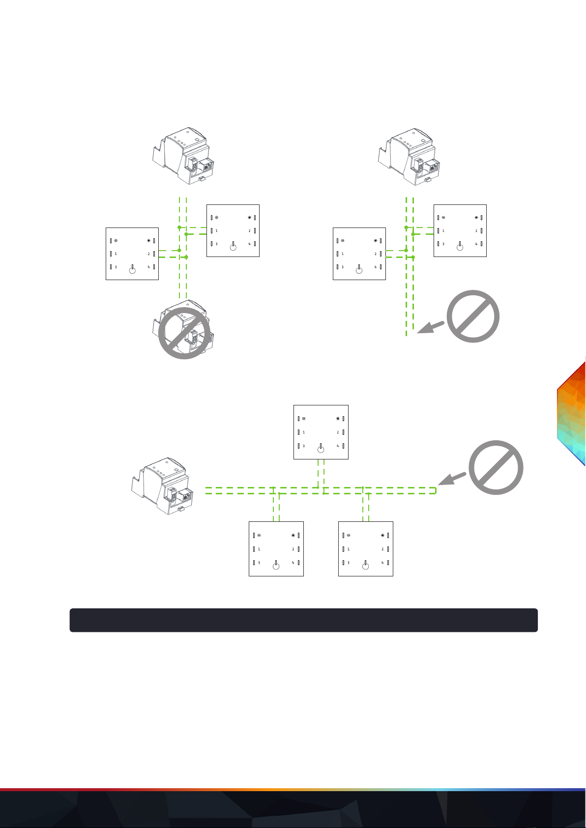
2.2 Invalid congurations
Donotaddasecondmastertoane:bus
network!
Donotleaveanywiresopen!Openwireswillcausesignal
reectionsandthereforedisruptcommunication.
SYMPL e:bus Node
SYMPL e:bus Node SYMPL e:bus Node
Donotcreatecreateshort-circuits.
The + and – cables must not be directly
connected!
SYMPL e:bus Node
3 Cable types and lengths
3.1 Cable types
The maximum cable length is greatly dependent on device count, topology and cable types as well. Approved
cabletypesfore:busareAWG16(1.5sqmm)cablesandAWG24(0.28sqmm)Cat5orJ-Y(St)Ycables.The
following table shows valuable key facts:
IntroductionManual—e:busIntroductionManual| Cable types and lengths
content

WWW.TRAXON-ECUE.COM ©2023 traxon technologies. All rights reserved. e:bus Introduction Manual 07/23 Sheet: 06 / 07
3.2 General run lengths
Device
count
AWG 16 (1,5 sqmm) AWG 24 (0,28 sqmm)
Cat5 Cable or J-Y(St)Y
bus topology free topology bus topology free topology
1400 m / 1312 feet 100m/328feet 400 m / 1312 feet 100m/328feet
2400 m / 1312 feet 100m/328feet 268m/879feet 100m/328feet
4400 m / 1312 feet 100m/328feet 133 m / 436 feet 100m/328feet
6400 m / 1312 feet 100m/328feet 88m/288feet 82m/269feet
8400 m / 1312 feet 100m/328feet 66 m / 216 feet 61 m / 200 feet
4 Special cabling conditions
4.1 Glass Touch
FortheGlassTouchthevaluesabovearenotvalid.Instead,watchtheserequirements:
yUse2x0.5sqmm.
yUseadirectconnectionfromSYMPLe:busNodetoGlassTouch,nobranching.
yMaximumcablelengthis100m.
5 e:bus, DALI and DMX
5.1 DALI
DigitalAddressableLightingInterface(DALI)isastandardforcontrollightinginbuildings.Itwasestablished
asasuccessorfor0...10Vlightingcontrolsystems,andasanopenstandardalternativetoDigitalSignal
Interface(DSI),onwhichitisbased.TheDALIstandard,whichisspeciedintheIEC60929standardfor
uorescentlampballasts,encompassesthecommunicationsprotocolandelectricalinterfaceforlighting
control networks.
5.2 DMX
DMX512(DigitalMultiplex)isastandardfordigitalcommunicationnetworkstocontrolstagelightingand
eectssuchasfogmachinesandmovinglights.DMX512employsEIA-485dierentialsignalingatitsphysical
layer,inconjunctionwithavariable-size,packetbasedcommunicationprotocolat250kBit/s.Itis
unidirectionalanddoesnotincludeautomaticerrorcheckingandcorrection.DMXisthemostused
connection type in lighting control.
5.3 Comparison
Feature e:bus DALI DMX
Includes protocol
Self-organizing network - -
Freetopologywiring -
Linkpower - -
Polarity-insensitive - -
High-Speed signaling -
IntroductionManual—e:busIntroductionManual| Special cabling conditions
content

This manual suits for next models
1


