PRO Light Color Fusion User manual

Color Fusion
User Manual
Please read the instructions carefully before use
1A
TABLE OF CONTENTS
1. Safety Instructions
2. Technical Specifications
3. Installation
3.1 Fuse Replacement
4. How to Set the Unit
4.1. Control Panel
4.2. Main Function
5. DMX512 Address setting
6. How to control the fixture
7. DMX512 Connection
8. Fixture Cleaning
2A
1. Safety Introductions
WARNING
Please keep the User Manual for future consultation. Please be sure receive this
instruction booklet.
Unpack and check carefully there is no transportation damage before using the fixture.
Please ensure the voltage and frequency of power supply match the power
requirements of the fixture.
It’s important to ground the yellow/green conductor to earth in order to avoid electric
shock.
Disconnect main power before servicing and maintenance.
Use safety chain when fixes this fixture. Don’t handle the fixture by taking its head only,
but always by taking its base.
Maximum ambient temperature is Ta : 40℃.
In the event of serious operating problem, stop using the fixture immediately. Never try
to repair the fixture by yourself. Repairs carried out by unskilled people can lead to
damage or malfunction. Please contact the nearest authorized technical assistance
center. Always use the same type spare parts.
Do not connect the device to any dimmer pack.
Do not touch any wire during operation and there might be a hazard of electric shock.
To prevent or reduce the risk of electrical shock or fire, do not expose the fixture to rain
or moisture.
The housing must be replaced if they are visibly damaged.
Do not look directly at the LED light beam while it may cause some eye damaged.
There are no user serviceable parts inside the fixture. Do not open the housing or
attempt any repairs by yourself. In the unlikely event your fixture may require service,
please contact your nearest dealer.
Please read the instructions carefully which includes important
information about the installation, operation and maintenance.
3A
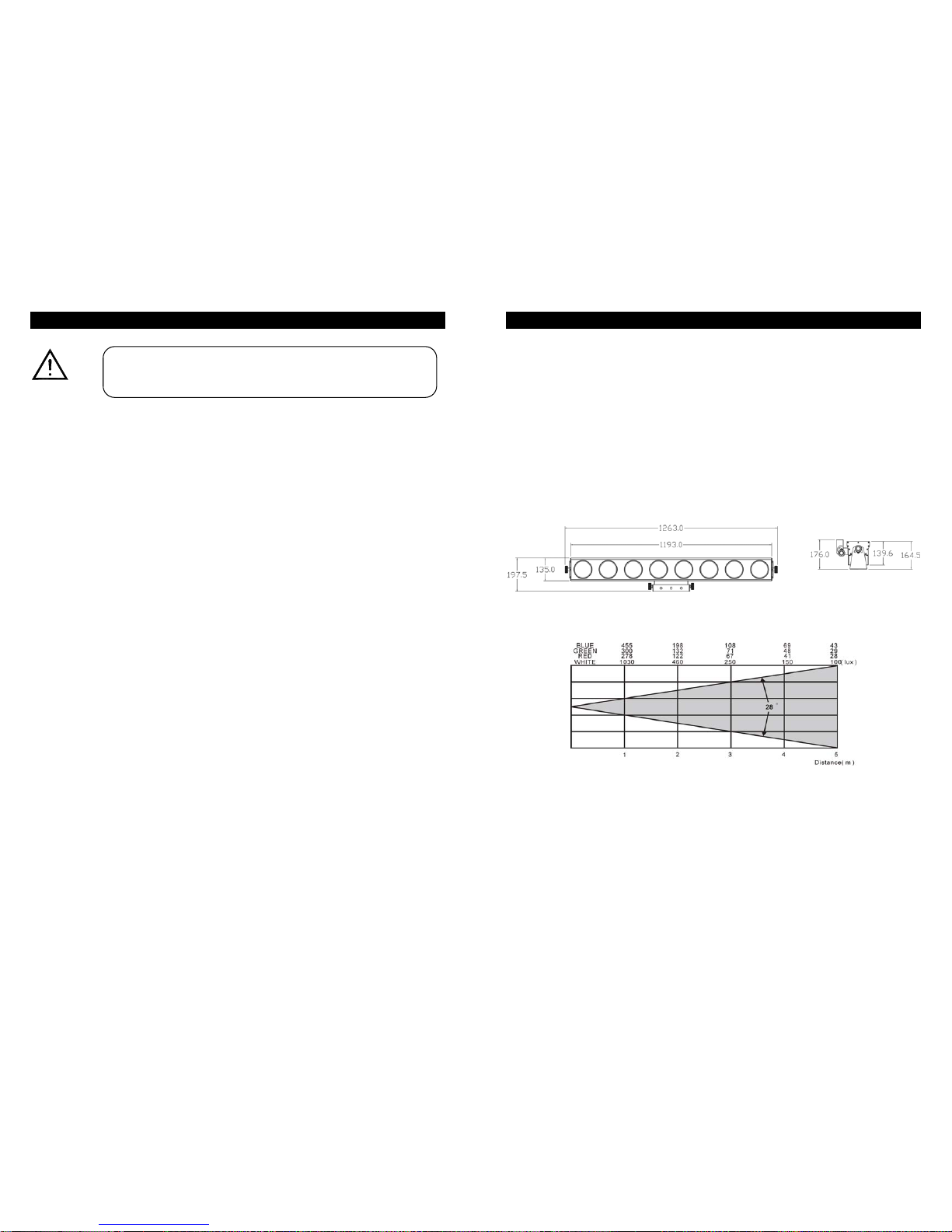
2. Technical Specifications
¥Power supply
AC 120V 60Hz
AC 230/240/250V 50/60Hz
Power consumption:105 Watts
¥LED
Red 200pcs, Green 200pcs, Blue 208pcs
¥Channels
6, 9, 15, 27, 24 channel mode
¥Dimension:1192 x 135 x 139.6 mm
¥Weight:10 kg
¥Luminous intensity:
4A
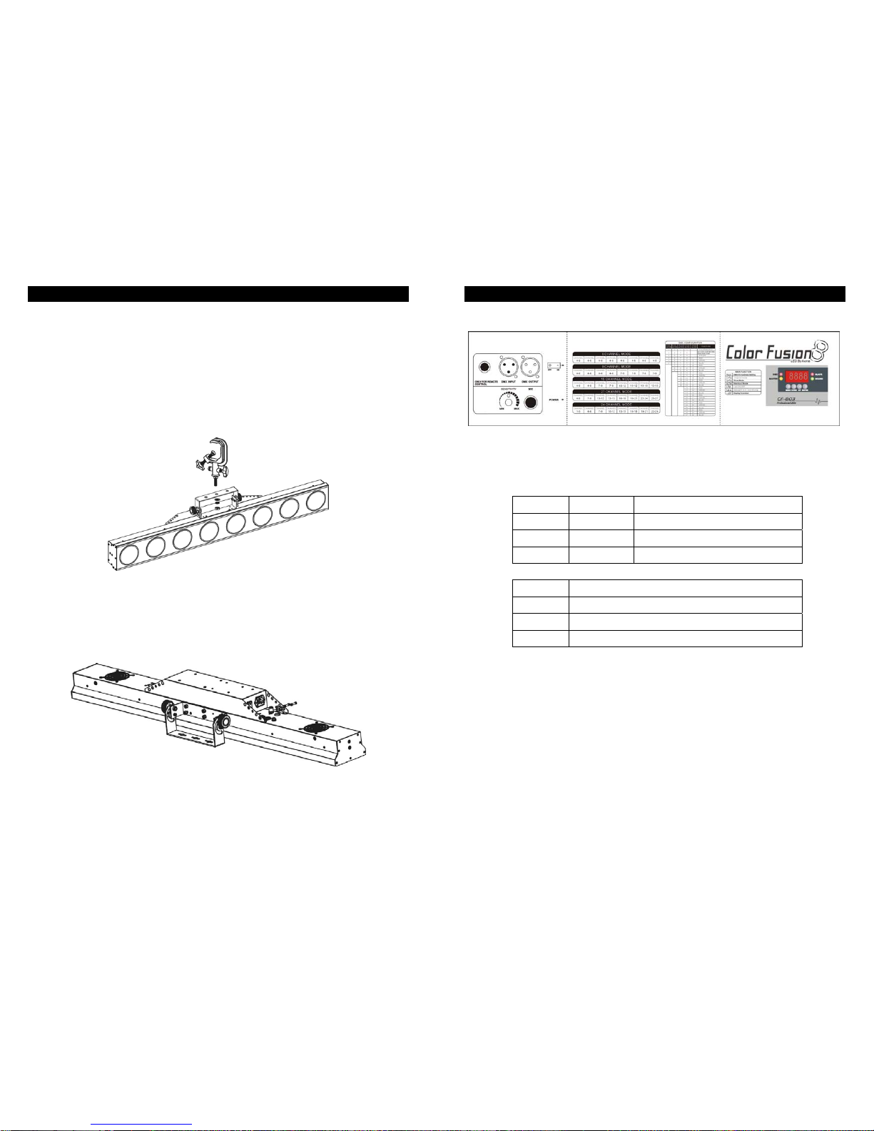
3. Installation
The fixture is able to hanging on the truss to increase the pleasured ambience.
Please check the voltage before plugging the power.
Do not use an electrical dimmer system, it will damage the inside electronics.
The unit should be mounted via screw holes on the bracket.
Always ensure the unit is firmly fixed to avoiding vibration and slipping while operating.
Always ensure the structure is strong enough to support a weight of 10kgs for each unit.
3.1 Fuse Replacement
The fuse of Color Fusion may be replaced as below.
First, disconnectAC mains power before replacing and replace with the same fuse.
5A
4.How to Set the Unit
4.1 Control Panel
Display
To show the menu and selected function
LED
DMX On DMX input present
MASTER On Master mode
SLAVE On Slave mode
SOUND Flashing Sound activation
Button
MENU To select the programming functions
DOWN To go backward in the selected functions
UP To go forward in the selected functions
ENTER To confirm the selected functions
Remote controller input
By connecting to the 1/4” microphone jack to control the unit via Stand by, Function, and
Mode function.
Sensitivity
To adjust the sound sensitivity
Microphone
To receive audio signal for sound activated.
DMX input/output
For DMX 512 link, use 3-pin XLR plug cable to link the unit together.

6A
4.2. Main Function
To select any of the pre-set functions, press the MENU button until the required one is
shown on the display. Select the function by ENTER button and the display will blink. Use
DOWN and UP button to change the mode. Once the required mode has been selected,
press the ENTER button to setup or it will automatically return to the main functions without
any change after idling 8 seconds. To go back to the functions without any change press the
MENU button. The main functions are shown below:
7A
DMX 512 Address Setting
Press the MENU button until the is shown on the display. Pressing ENTER button
and the display will blink. Use DOWN and UP button to change the DMX 512 address. Once
the address has been selected, press the ENTER button to setup or automatically return to
the main functions without any change after 8 seconds. To go back to the functions
without any change press the MENU button again.
6, 9, 15, 27, 24 Channel Mode
Press the MENU button until the is shown on the display. Pressing ENTER button
and the display will blink. Use DOWN and UP button to select the 6-ch, 9-ch, 15-ch, 27-ch or
24-ch Channel Mode. Once the mode has been selected, press the ENTER button to setup
or automatically return to the main functions without any change after 8 seconds. To go back
to the functions without any change press the MENU button again.
Show Mode
Press the MENU button until the is showing on the display. Pressing ENTER button
and the display will blink. Use DOWN and UP button to select the (random mode)
or (show 1) …(show 8) or (auto fade) mode. Once the mode has
been selected, press the ENTER button to setup or automatically return to the main
functions without any change after 8 seconds. To go back to the functions without any
change press the MENU button again.
In show mode, you can press the Enter button to set the chase speed (1~8).
Blackout Mode
Press the MENU button until the is shown on the display. Pressing ENTER button
and the display will blink. Use DOWN and UP button to select the (yes blackout) or
(no blackout) mode. Once the mode has been selected, press the ENTER button to
setup or automatically return to the main functions without any change after 8 seconds. To
go back to the functions without any change press the MENU button again.

8A
Led Display
Press the MENU button until the is showing on the display. Pressing ENTER button
and the display will blink. Use DOWN and UP button to select the (Led on) or
(Led off) mode. Once the mode has been selected, press the ENTER button to
setup or automatically return to the main functions without any change after 8 seconds. To
go back to the functions without any change press the MENU button again.
Color Mode
Press the MENU button until the is showing on the display. Pressing ENTER button
and the display will blink. Use DOWN and UP button to select the (color 1) or …
(color 9) or (manual color) mode. Once the mode has been selected, press
the ENTER button to setup. Use DOWN and UP button to set the range. The setting will be
store in the memory. To go back to the functions without any change press the MENU button
again.
In manual color mode, you can use DOWN and UP button to set the
(Red 0~255)
(Green 0~255)
(Blue 0 ~255)
Display Inversion
It is good for you to install the unit on the floor or under ceiling. Press the MENU button until
the is blinking on the display. Use the ENTER button to change to the mode
(display inversion), It will automatically store after 8 seconds. Or press the ENTER
button again return to the mode (display normal). To go back to the functions press
the MENU button.
Display normal mode for the fixture putting on the floor.
Display inversion mode for the fixture fixing under ceiling.
9A
5. DMX512 Address Setting
A. By LED Display Panel
1.Each fixture needs to have an address setting to receive the data sent from the controller.
The address number is between 0-511 (usually 0 & 1 are equal to 1). The address, also
know as the start channel, is the first channel used to receive instructions the controller.
2.The fixture uses six channels. (Fixture 1 = 1, Fixture 2 = 7, Fixture 3 = 13, Fixture 4 = 19,
Fixture…)
3.No need to turn the fixture off when you change the DMX address, as new DMX address
setting will be effected at once. Every time you turn the fixture on, it will be ready to
receive DMX signal or run the built-in programs.
B. By CA-T DMX TESTER
The fixture can be set the DMX address remotely by CA-T DMX TESTER. Please refer to
the CA-T user manual to set the DMX address to the fixture.
10A
C. By Universal DMX controller
The fixtures can be remote setting DMX address by universal DMX controller. First,
programming two scenes into one chase and then link the fixtures to the universal DMX
controller. When you run the chase, all series fixtures will set start DMX address
automatically.
In the two scenes, Ch1 and Ch2 for auto DMX address setting mode, the values will never
change. Ch3 and Ch4 for setting the DMX address, Ch3 or Ch4 value must be setting value
together. Ch3 will be only set 0 or 1 and Ch4 will be set from 0 to 255.
DMX start address = (Ch3 x 256) + Ch4 + 1
For example 1:
Setting the four fixtures with DMX start address = 1
1. Edit the scene 1Ch1=0, Ch2=255, Ch3=0, Ch4=0
2. Edit the scene 2Ch1=255, Ch2=0, Ch3=0, Ch4=0
3. Programming two scenes into a chase and link the fixtures to the universal DMX
controller.
4. Running the chase and all series fixtures will be setting start DMX address automatically.
For example 2:
Setting the four fixtures with DMX start address = 10
1. Edit the scene 1Ch1=0, Ch2=255, Ch3=0, Ch4=9
2. Edit the scene 2Ch1=255, Ch2=0, Ch3=0, Ch4=9
3. Programming two scenes into a chase and link the fixtures to the universal DMX
controller.
4. Running the chase and all series fixtures will be setting start DMX address automatically.
For example 3:
Setting the four fixtures DMX start address = 257
1. Edit the scene 1Ch1=0, Ch2=255, Ch3=1, Ch4=0
2. Edit the scene 2Ch1=255,Ch2=0, Ch3=1, Ch4=0
3. Programming two scenes into a chase and link the fixtures to the universal DMX
controller.
4. Running the chase and all series fixtures will be setting start DMX address automatically.
11A
6. How to control the fixture
There are three ways to set-up the DMX address:
A. Universal DMX controller
B. Master/Slave operation
C. Easy controller (by CA-8)
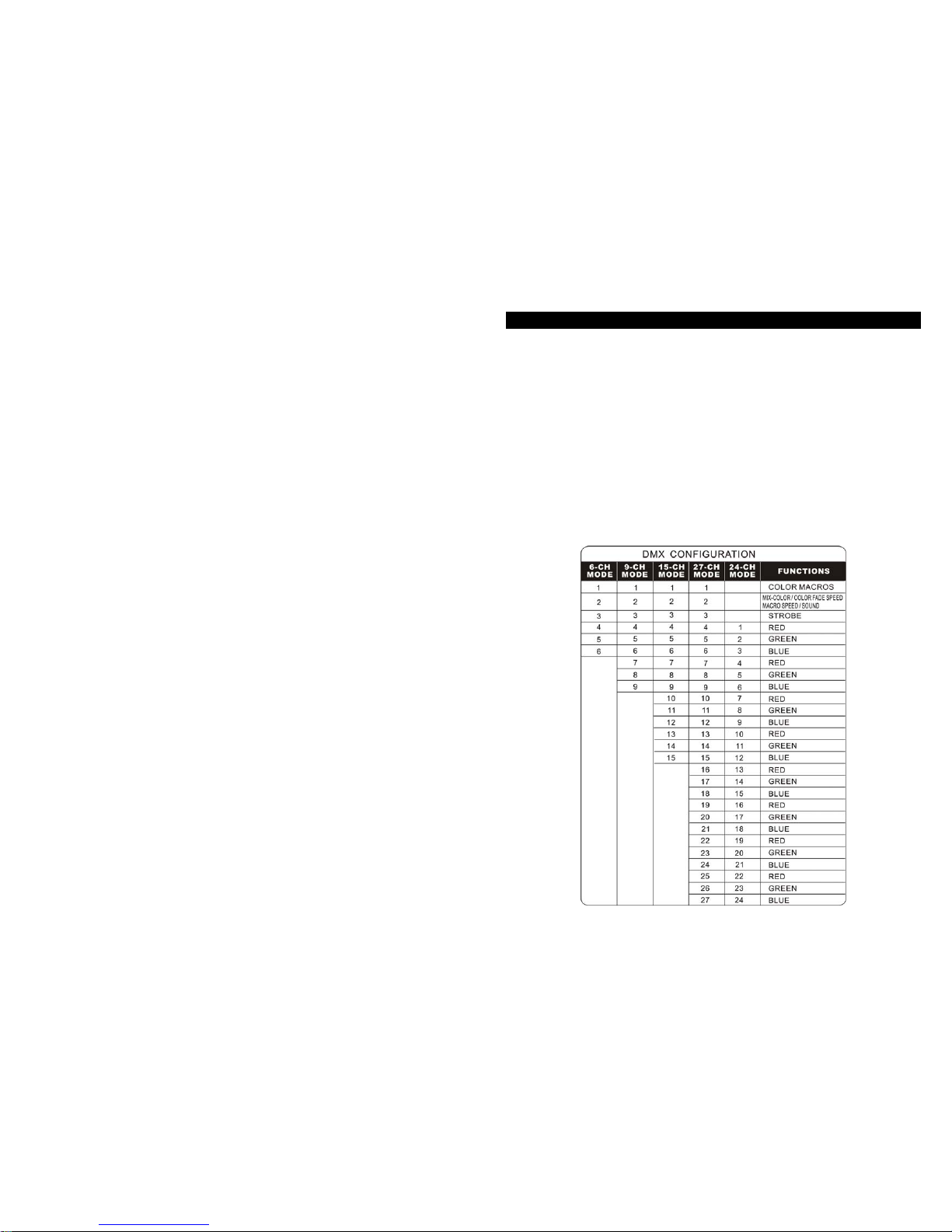
A. Universal DMX controller
The user need to set the lighting channel mode first while control by universal DMX
controller. The fixture has four kinds of channel modes (6-ch, 9-ch, 15-ch, 27-ch, 24-ch). It
can set the channel mode from its LED display panel. Please refer to the following diagram
to use your controller to activate the fixture.
12A
13A
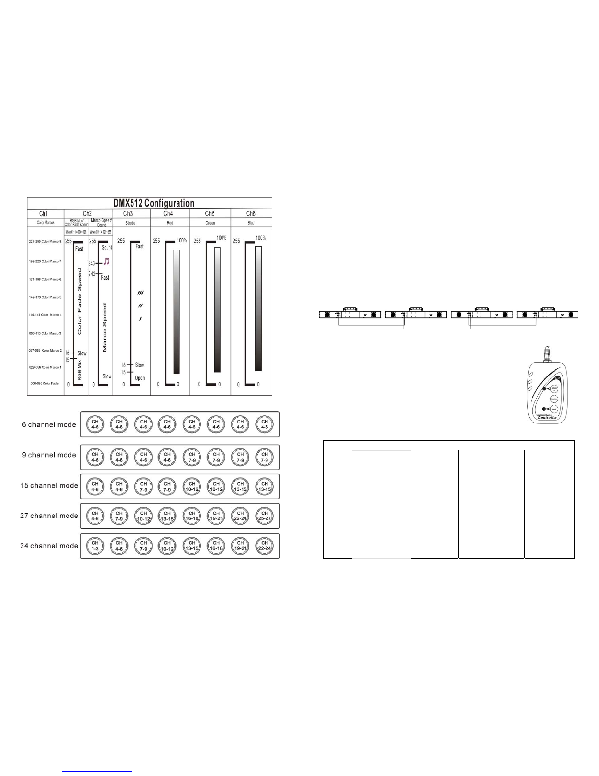
B. Master/Slave operation
The fixtures will allow you to link others fixtures together and operate without a controller. In
Master/Slave mode, the first fixture will control the others to give an automatic, sound
activated, synchronized light show. This function is good when you want an instant show.
The first unit it’s DMX input cable will have nothing connect it, and the other fixtures will be
set in slave mode automatically. Their DMX input cables connect the last fixture DMX output
cable (daisy chain). Any fixture can act as a Master or as a Slave. Please refer to the
following diagram to link the others fixtures.
C. Easy Controller (by CA-8)
The easy remote control is used only in master/slave mode. There is a
terminator for connect the easy controller inside the fixture. By
connecting the cable into DMX IN waterproof cable entry gland to the
CA-8 terminator of the first fixture, you will find that the remote control
on the first fixture will control all the other fixtures for Stand by, Function
and Mode functions.
Blackout To blackout all the fixture
Function Strobe
1.Synchronous
strobe in white
2. Synchronous
strobe in rainbow
3. Synchronous
sound in white
4. Synchronous
sound in rainbow
Select 9 Colors
1. Red
2. Orange
3. Yellow
4. Green
5. Cyan
6. Blue
7. Purple
8. Magenta
9. White
Select 9 Show modes
1. Show 1
2. Show 2
3. Show 3
4. Show 4
5. Show 5
6. Show 6
7. Show 7
8. Show 8
9. Auto fade
Setting speed
1.Slow speed
2.Middle speed
3.Fast speed
Mode Sound
(LED OFF) Latch
(LED on) Chase
(LED blink) Speed
(LED Fast blink)

14A
7. DMX512 Connection
The DMX 512 is widely used in intelligent lighting control, with a maximum of 512 channels.
1. Connect the unit together in a “daisy chain” by XLR plug cable from the output of the unit
to the input of the next unit. The cable cannot be branched or split to a “Y” cable.
Inadequate or damaged cables, soldered joints or corroded connectors can easily distort
the signal and shut down the system
2. The DMX output and input connectors are pass-through to maintain the DMX circuit when
no power is connected to the fixture.
3. At last fixture, the DMX cable has to be terminated with a terminator to reduce signal
errors. Solder a 120-ohm 1/4W resistor between pin 2(DMX-) and pin 3(DMX+) into a
3-pin XLR-plug and plug it in the DMX-output of the last fixture.
4. Each lighting unit needs to have an address set to receive the data sent by the controller.
The address number is between 0-511 (usually 0 & 1 are equal to 1).
5. 3 pin XLR connectors are more popular than 5 pins XLR.
3 pin XLR: Pin 1: GND, Pin 2: Negative signal (-), Pin 3: Positive signal (+)
5pin XLR: Pin 1: GND, Pin 2: Negative signal (-), Pin 3: Positive signal (+)
15A
8. Fixture Cleaning
The cleaning of internal must be carried out periodically to optimize light output. Cleaning
frequency depends on the environment in which the fixture operates: damp, smoky or
particularly dirty surrounding can cause greater accumulation of dirt on the fixture’s optics.
Clean with soft cloth using normal glass cleaning fluid.
Always dry the parts carefully.
Clean the external optics at least every 20 days. Clean the internal optics at least every
30/60 days.
Innovation, Quality, Performance
Table of contents
Other PRO Light Dj Equipment manuals

PRO Light
PRO Light ELUM120A User manual

PRO Light
PRO Light EQUINOX User manual

PRO Light
PRO Light LUMA700 User manual

PRO Light
PRO Light TRANSCENSION DMX OPERATOR 2 User manual

PRO Light
PRO Light TRIBE LUMIPAR 12IP User manual

PRO Light
PRO Light LED-707 User manual

PRO Light
PRO Light EQLED052 User manual

PRO Light
PRO Light CP-64U HP User manual

PRO Light
PRO Light elumen8 User manual


