TRC PRO 10 SPORT Installation guide

ASSEMBLY
INSTRU
TION
MANUAL
.
FOR
PRO
10
SPORT
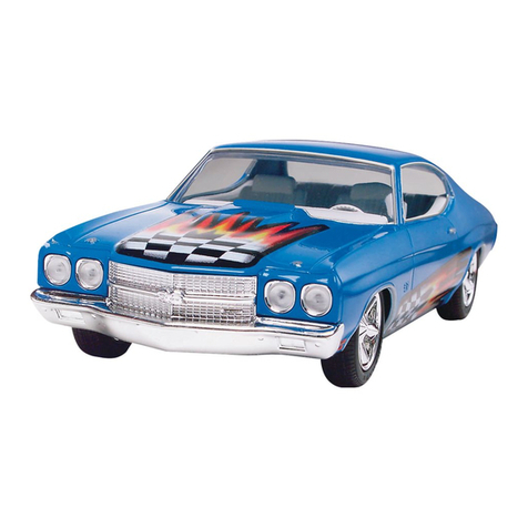
Pictured with optional bumper & side wing.
•
TO
BE
USED
WITH
STEP-BY-STEP
PICTORIAL
REFERENCE

THEPR
0
-10
1988
ROAR
NATIONAL
CHAMPION
I
Congratulations!
You have
now
joined
the wonderful world
of
RIC
racing.
Many
hours
of
fun
are
ahead
of
you. The
PR0-1
0
SPORT
you
have purchased
is
based
on
the nationalwinning
design
of
the
PR0-10
ELITE,
one
of
the top
1110th
scale T-bar
oval
and
on
road
cars
in
the world.
Two
of
the
most
successful radio controlled
car
manufacturers in the world,Co
mposite
c
raft
and
TRC
ha
ve
joined
forces
and
have
in
troduced
an
entry level racing machine
at
an
entry levelprice
without sacrificing race performance. The
PR0-
10
SPORT
can take
you
from the beginning
all
the
way
to the top.
As
you
r skill level increases, t
he
PR0-1
0
SPORT
can
be
up-dated to improved perform-
ance
and
will
be
readyto handleanything
you
can
give it. The
PR0-1
0 series
of
cars are still the
most simple cars to b
uild
and
maintain
on
the
circuit. Precision molded
and
machined compo-
nents make the
PR0-10
SPORT
a snap to
put
together,
but
you
still
need
to
read
and
follow the
instructions. Theywill
give
you
tips
in
the assem-
bly
process
that
w
ill
help
you
when
it
is
time to
race.
TAKE
YOUR TIME I
How
careful
you
assemble the
car
now
is
going
to determine
how
well
it
performs
on
the track. Don't
be
in a hurry.
You won't win anything
for
the fastest chassis
assembly.
••••••••••••••••••••••
•
AS
S
EMBL
Y TIPS
FROM
•
• •
• THE
FACTORY
•
•• •• • •••• •••• ••••• • •••
Before
you
get
started, here
are
some
suggestions
and
tips
that
w
ill
make the assembly
of
your
kita little easier.
Glance
through
the instructions
and
picturesoncebefore
you
startto assemble the kit.
This will help
get
you
familiarized with the
assemblysteps
and
the p
ic
tures.
2
To help eliminateconfusion,
only
open the
partsbags when they are calledfor in the instruc-
tions. Otherwise
you
might
mix
up
small parts
which willmake the assemblymuch more difficult.
When
you
empty
the parts bags, use a
paper
plate
or
a
small
containerto empty
it
in.
This
will
keep
parts from rolling
off
t
he
table
and
being
lost foreve
r.
When
you
are putting screws into plastic
pieces, be sure that
you
do
not
over
tighten them.
This
could
result in t
he
threads in theplasticstrip-
ping. Tighten the screws untilt
hey
are snug.
Check
all
the
hol
es
in t
he
nylon pieces.
Some
of
the holesare
no
t tapped. You should
tap
these holes with the correctsize tapbeforeputting
a
screw
in
the piece.
All
molded
nylon pieces will have a small
amount
of
flashing. Before
you
assemble these
pieces
it
is
a
good
idea to remove
it
with a hob
by
knife. In the instructions, certain parts are
referred to as left
and
right. Imagine yourself sit-
ting in a full size
car
in
the driver's seat. The
driver's side
is
what will
be
referred to
as
t
he
le
ft
side. The passengerside w
ill
be
referred
to
as
the
right side. Please keep this in
mind
while
you
are
assembling
your
car.
The step numbers
in
this manual corre-
spond
to t
he
pictur
es
in
the
pic
torial assembly
manual. Use both
for
the assemblyof this kit.
Due
to COMPOSITECRAFT & TRC's
on-going development program, certain parts in
the pictorial assembly
manual
may
be
different
from the actual
parts
in
the k
it.
/
'
Item
s
required
to
c
omplete
this
c
ar
1-
Two
channelradio system
1-
Speed
controldevice
1 -6
or
7 cellbattery
pack
-saddle type
1-
05
electric
motor
1 -
111
Oth
scale
body
(
if
not
included)
1 -Servo
saver
1 -Batterychargingsystem

/
'
/
15138
#5562
15140
15142
15144
15156
#5502
#5523
#5574
15476
15560
15166
15424
15428
#5502
#5506
#5540
15561
#5590
#5316
#5318
115320
#5322
#5328
Tools
and
supplies
needed
to
build
this
kit
#2
phillips screwdriver-large I Hobbyknife
SmallpliersI Needle nosepliersI Medium file
Shock
oil
I
20
-
25
Weight 1Silicone lube
_/
"'\
OPTIONAL TOOLS
N
ut
driversetI Dremel Tool
4-40tap, 8-32 tap
_/
•••••••••••••••••
:PRO
-10
SPORT
:
:
KIT
CONTENTS :
•••••••••••••••••
(
sAG#
1 FOR
PR0-10
SPORT)
MOLDED
NYLON
FRONT
CROSS
BAR...................1
1
11
6"
A
LLEN
WRENCH
....
..
....................................... 1
KING
PINS
FOR
NYLON
FRONT
CROSS
BAR
.......2
2
DEGREE
CASTER
SHIMS
.....................................2
118"
STEERING
BLOCKS
..........................................2
.022FRONTSUSPENSION
SPRINGS
.....................2
114"
X.060
STEEL
WASHER
....................................2
4-40X
114
"
STEEL
FLATHEAD
SCREWS
................2
8-32X
112"
ALUMINUM
FLATHEAD
SCREWS
......
...
2
118
" X
114
"
STEEL
WASHER
................................
...
..
2
118
" X5116"
FLANGED
OILITE
BUSHINGS
....
...
....
..
.4
1/8"
E-CLIP .........
..
............
..
...
..
................................
10
(
sAG#
1A FOR
PR0-10
SPORT )
SERVO
MOUNTI
NG
KIT
.........................................
..
1
3"
MOLDED
NYLONBODYPOST............................2
BODY
POST
COLLAR................................................2
4-40X
114
"
STEEL
FLATHEAD
SCREW...................2
4-40X
112
"
STEEL
FLATHEAD
SCREW......
...
..
........2
4-40 X
118
" SETSCREW...........................................2
.
050"
STEEL
ALLEN
WRENCH
................................. 1
STEERING
LINKAGEKIT...
..
.............
..
...................... 1
(s
AG#
2 FOR
PR0-10
SPORT )
SUPPORTPLATE PIVOT
BALL
& SOCKETSET.....1
FIBERGLASS
REAR
T-BAR
......................................1
TOP
MOTOR
BLOCK
BRACE
...............................
....
1
NYLON
MOTOR
BLOCKSET................................... 1
RIDEHEIGHT
ADJUSTOR
SET................................ 1
•
3
#5502 4-40X 11
4"
STEEL
FLATHEAD
SCREW
................... 1
#5514 5-40X 11
4"
STEEL
SOCKET
HEAD
CAP
SCREW
...
4
8-32X
318"
STEEL
SOCKET
HEAD
SCREWS
.........
2
15523 8-32X
112"
ALUMINUM
FLATHEAD
SCREWS
.......
.4
#5574
118"
X 114"
STEEL
WASHER
.....................................1
(
sAG#
3 FORPRO -10SPORT )
#5314
MO
LDED
NYLON
T-BAR
SUPPORT
PLATE
............ 1
#5334
REAR
DAMPENER
KIT........................................
.....
1
15426
#5428
#5523
#5340
#5342
#5510
#5540
#5553
#5512
ANTENNA
MOUNT...........
..
...
....................................1
4"
NYLON
BODY
POSTS
..........................................2
BODYPOST
COLLARS
............................................2
8-32X
112"
ALUMINUM
FLATHEAD
SCREW
........... 1
REAR
SUSPENSION
SPRINGS
...............................2
NYLON
SPRING
LOCATORS
...................................2
4-40X 11
4"
STEEL
FLATHEAD
SCREW...................1
4-40X 1"
STEEL
FLATHEAD
SCREW
......................2
4
·40
X
118"
STEEL
SETSCREW..............................2
4-40
STEEL
LOCKNUT............................................2
5-40X
318"
STEEL
FLATHEAD
SCREWS
................4
(_sAG#
4 FOR PR0-10SPORT)
#676 120
TOOTH
SPUR
GEAR
......................................... 1
#5558
8-32
NYLON
LOCKNUT........................................... 1
#5663
STEEL
DIFFAXLE .................................................... 1
#5667
MOLDED
NYLON
DIFF
HUB
..................................... 1
#5669
MOLDED
NYLON
WHEEL
HUB
................................1
#5677
THRUST
BEARING
SET...........................................1
#5678 CONE WASHER ........................................................ 1
#5566 3/32" ALLEN
WRENCH
.........................
..
..................1
#5685 AXLE
SPACER
SET..................................................1
#5546 10-32 X
114"
STEEL
SET
SCREW
............................2
#5674 DIFF DRIVERINGS.........................
....
......................2
#5690 114" X
318"
NYLON
DIFF
BUSHINGS
........................2
#5478
114"
X
318"
FLANGED
OILITE
BUSHINGS
................2
#5516 5-40 X
318"
STEEL
SOCKET
HEAD
CAP
SCREW
...
8
#5672
STANDARD
DIFF
BALLS
..........................................8
Checkthe contents
of
each bagwith the list above.
These bags have been checked at the factory, but it
is
possible that a part
may
be
missing. For missing parts call
704
-
982
-0507. Make sure you use part numbers when
ordering.
ONE
FINAL NQTE I
Assemblystep numbers correspond
to
the
picturenumbers. Complete eachstepbeforegoing
on
to
the next.
NOW
LET'S
GETSTABTED
I

STEP# 1
We
will needto do a slight amount
of
chassisprepbefore we startthe assembly.
Locate the chassis,
and
you will notice that
on
one
side the holes in the chassis are countersunk for screw
heads. This is the bottom
of
the chassis. On the top
of
the
chassis
we
want to file the batteryslots
at
a slightangle so
the batteries will not
be
sitting
on
a sharpcornerthat could
cut the protective heat shrink
on
them
and
cause them to
short out. Lightly file both the front
and
back
of
all
the
batteryslots so the cells willhavea flat spotto sit
in.
Before
you do this, itmight
be
a
good
idea to spreadsome newspa-
per
out
to
catch the filings. You will also use strapping tape
to
holdthe batteries in the chassis. You will needto file the
sections
of
the chassis that the tape goes around.
If
these
placesare leftsharp, theywill
cut
the tape
and
the batteries
willfallout. Just round
off
these edges.
When you are finished, wash
off
the chassis with
water
and
dry
it
off
witha
paper
towel.Then make sure you
wash your hands with soap
and
water. Clean up the dust
anddispose.
You
are
now
finished with step #1. Put a check
mark in the box
to
show that this step
is
complete. After
you've completed each step from nowon, check
off
its box
soyou know which part
of
the assemblyyou are on in case
of
an
interruption. You won't miss anysteps this
way.
PR0-10
SPORT
FRONT
END
ASSEMBLY
STEP#
2 Open bag #1
and
empty the
contents.
For
the time being do not open bag #1A. Locate
thefrontnyloncross
bar
.Checkoverthe beamto makesure
all the flashing,
if
any, is removed around the holes.
The
caster
on
this front
end
is 0 degrees. This means the king
pins will
be
straight up
and
down. You need
to
run a small
amount
of
caster
in
the front end, so locate the two caster
shims. These are molded
at
2 degrees each. Fasten the
frontbeam
to
the chassiswith the castershims betweenthe
chassis
and
the frontbeam.
Use
an 8-32x
112"
screw in the
front
and
a 4-40x
114"
screwin the rear
of
the beamblock.
Tighten
all
screwscompletely.
STEP#
3 Locate the two front steering
blocks
and
remove any flashing from around the holes
with a hobby knife.
STEP#
4 Locate the two front kingpins.
You
will notice that they have a groove in each end. These
groovesarefor
thee
-clips. Putonee-clip
on
one
end
of
each
kingpin.
STEP# 5 Next,
put
a king pin
in
the bottom
arm on the front cross
bar
so it sticks through about
118".
Now slide a steering block
on
the king pin
as
shown
and
push the king
pin
up until
it
reaches the top
of
the steering
4
block
and
sticks throughabouta
1116".
There is nota leftor
a right
on
the steeringblocks. Theyarethe same. Nowputa
spring
on
the king
pin
on
top
of
the steeringblock, then a
thick washer
and
push the king
pin
through the top
of
the
axle beam. Put an e-clip in the top groove
to
hold the
assembly inplace.
STEP#
6 Open
bag
#1A. Findthe frontbody
posts. Fasten them to the chassis using the 4-40 x 1/2"
screws. Holdthepostswithplierswhiletighteningthescrews.
Make sure you do notovertighten the screws
and
strip out
the threads. Put the body
post
collars
on
the posts just
underthelastset
of
hood
pin
holes
and
lockinplacewiththe
4-40 x
118"
set screws. These will
be
adjusted laterto the
body.
STEP#
7 Putthe seNomountingpostsin the
chassis
as
shownusinga 4-40x
114"
screw.
For
now,
put
the
seNo mounting face plates on the posts with the
#2
X
318"
selftap screws so theydo
not
get
lost These will
hold
the
steeringseNo in placelater.
PR0-10
SPORT
REAR
T-SAR
ASSEMBLY
STEP#
8 Open bag
#2
and
locate the steel
pivotball
and
the
114"
steelwasher. Fasten thepivotballto
the t-bar in the middle hole with the washer in between the
pivot ballandthe t-bar
as
shown using a 4-40x
114"
screw.
It would
be
a good idea
to
lock lite this screw.
Do
not use
pliers to holdthe ball while tightening the screw.
STEP#
9 Find the pivot ball nylon socket.
Using a lightoil, coatthe inside
of
the socketthatsnapsonto
thepivotball
as
well
as
the pivotball. Snapthepivotsocket
onto the pivotball. Move it around.
It
willprobablybe a little
tight. Afterthe
car
hasbeenruna few times itwillloosen
up.
STEP#
10 Next, findthetworearmotorblocks.
Fasten them to the rear t-bar using four 8-32 x
112"
aluminumflatheadscrews. Note:bothmotorblocks are the
sameshape. The
only
difference is in the holes for the ride
height adjustors. Be sure to
put
the blocks on the t-bar so
the rideheightadjustors will
be
on theoutside
of
theblocks.
Not
on
the inside.
STEP#
11
Now
find the ride height adjustor
set. You will notice that there are three different offsets in
them. This gives you the option
of
five different rear axle
heights, depending
on
how they are placed in the motor
blocks. Most
of
the racers run the axlein the middle setting,
butyou can referto the section
on
RIDE HEIGHTSET
UP.
When you have chosen the
set
you are goingto use, install
them in the motorblocks
as
shown. Be sure to trim
off
any
flashing that might
be
presentaroundthe edges.

STEP#
12 Next, fasten the
motor
blockbrace
to
the motorblocks, using four 5-40 x
114"
capscrews and
the 8-32 X 318" screws.
Put
the brace on so that the TRC
logo
is
facing
up
andto the rear
of
the t-
bar
as
shown_
PR0-10
SPORT
SUPPORT
PLATE
ASSEMBLY
STEP#
13 Open bag
#3
and
find the t-bar
supportplate. Usingfour5-40x
318"
flatheadscrew
s,
fasten
thesupportplateto thechassis asshow
n.
STEP#
14 Fasten the reardamperpostto the
t-bar support pla
te
as
shown using a 4-40 x 1
12
" screw.
Make sure you do
not
overtighten the screw. Also
be
sure
the holes
in
the posts are facing the front
and
rear
of
the
chassis. N
ot
side to side.
STEP#
15 Next, locate the
rear
damper
pushrod
and
install it in the rear motor block brace as
show
n.
STEP#
16
pushrodasshow
n.
Slide a
set
collarandspring on the
STEP#
17 Next, slide the t-
bar
assembly into
position underthe t-b
ar
supportplate that
is
on the chassis,
andslide the push rod into the middle hole
of
the damper
post.
STEP#
18 Next, slide the nylon pivotsocket
into the large hole in the nylont-barsupportplate.
STEP#
19 Now, using a 8-32x 112"aluminum
screw, fasten the front
of
the t-bar to the front hole
in
the
t-
bar
supportplate
and
lock into place usingan 8-32 nylon
lock nut.
STEP#
20
Slide anotherspring
and
set
collar
on thepush rodasshown. Using a 4-40set screw, tighten
the setcollar
on
the
pus
h rod to
hold
the assembly
in
place.
This will beadjustedlater.
STEP#
21 In each hole next to the pivot ball
in the t-bar, placea 4-40 x 1" screw.
STEP#
22 Put a rear suspension spring
over
eachscrewon top
of
thet-barsupportplate. Ontop
of
each
spr
ing, place a nylonspring locatoras show
n.
STEP#
23
Lockthis assemblyintoplace with
a 4-40 lock
nut
on each screw. Tighten the nuts until they
compress the springsapproximately25%
STEP#
24
Next, fasten the antennamount
on
the chassisusing a 4-40 x 114" screw.
5
STEP#
25
Next, fasten the
4"
bodyposts
to
the chassisusinga 4-40x
112"
screw. Make sureyou
do
not
over
tighten the screw
in
the
body
post. Put the bodypost
collarson the bodyposts
jus
t underthe lastset
of
hood
pin
holes
and
lockintoplacewitha 4-40x 1/8"setscrew. These
will
be
adjustedlaterto the body.
STEP#
26
Take a break. Go and
get
a cold
drink andsitback
and
tellyourseffwhatagreatjobyou have
done so far.
(DIFFERENTIAL ASSEMBLY )
STEP#
27
Locate bag #5 and empty into a
container. There are many small parts that will roll off a
table in this bag. Find the diffaxle. Slip one
of
thediffdrive
rings onto the hubonthe axleasshow
n.
Many racersuse a
drop
of
superglue, like
ZAP
or
HOT
STUFFtoholdthedrive
ring inplaceon the hub.
STEP#
28
Now locate the spur
gear
.
You
will
notice t
hat
the
gear
has two sets
of
holes
in
it. We will be
using the outside set
of
holes. Push an
118
"diffballin each
of
theoutside eight holes. Now
put
a smalldab
of
diffgrease
on eachball.
STEP#
29 Now slide the spur
gear
onto
the
diff
ax
le topped with the second diffdrive ring.
If
you find
something to stand the
diff
axle
in
while building, it makes
assemblymuch easier.
STEP#
30
Next, push a nylon bushing into
each endof thediffhub. Besure
to
trimanyflashingoff
from
the edge
of
thebushings. Makesuretheyfit
all
the w
ay
down
in the hole. Put a drop
of
light
oil
inside each bushingand
slidethehub assemblyonthe axle.Lineupthe drive ringon
t
op
of
thegear with the
diff
hub. This drive ring
may
also be
superglued
to
the hub.
STEP#
31 Now
put
the thin thrust washer on
the axle, inside the
diff
hub, followed
by
the black thrust
bearing,andthen thethick thrustwasher. Next, putthesteel
cone washeronthe axle
(small
end
up)
andlastly the 8-32
nylon lock nut. Tighten the
nut
just enough
to
hold
all
the
partsinplace. We willadjustitlater. Onlyuse a nylon nuton
thediff axle.
STEP#
32 Put the two 11
4"
x
318"
flanged
bushingsin theride heightadjustorsin the motorblocks. Put
a drop
of
light oilinside each bushing.
STEP
#
33
Next, find the nylon axle spacers.
Take the
118"
spacer
and
s
li
de it
on
the di
ff
axle. Slide the
assemblythrough the bearin
gs
in the rear
pod
.
