TREBING + HIMSTEDT SPI 3 User manual

Doc. Version 2.0
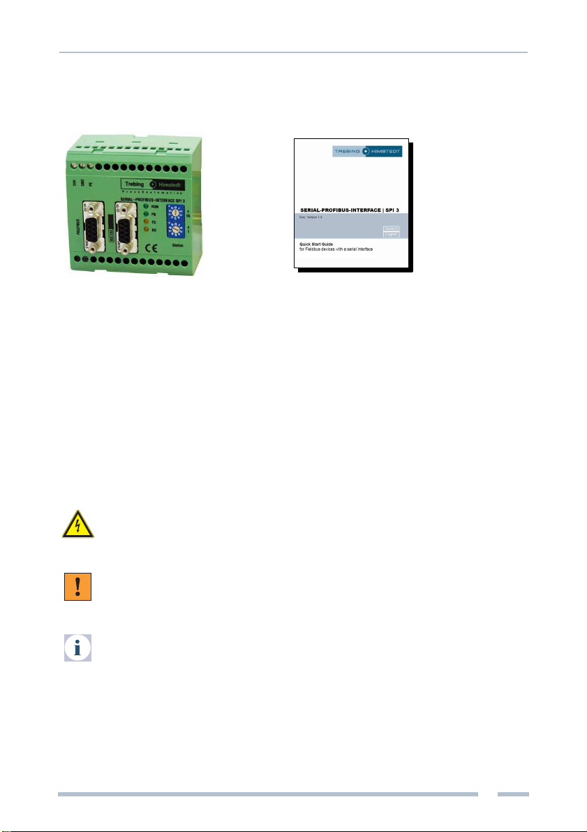
SERIAL-PROFIBUS-INTERFACE
SERIAL-PROFIBUS-INTERFACESERIAL-PROFIBUS-INTERFACE
SERIAL-PROFIBUS-INTERFACE | SPI 3
| SPI 3 | SPI 3
| SPI 3
for Fieldbus Devices with Serial Interface
– Sartocheck 4

Doc. Version 2.0 | Mai 2008
Dear customer
This online documentation is designed to help you with engineering, connecting up,
configuration and parameter setting of the SPI 3. Please feel free to contact our
Technical Support department if you need further help:
Trebing & Himstedt Prozessautomation GmbH & Co. KG
Technical Support Dept.
Wilhelm-Hennemann-Str. 13
19061 Schwerin, Germany
Telephone: +49 385 39572-500
Telefax: +49 385 39572-22
E-mail: [email protected]
Homepage: http://www.t-h.de
The information in this online documentation is the property of Trebing & Himstedt
Prozessautomation GmbH & Co. KG. This online documentation or extracts thereof
may only be duplicated or passed on tothird parties following explicit written approval
from Trebing & Himstedt Prozessautomation GmbH & Co. KG. The right is reserved
to make changes to this manual and to the SPI 3 device at any time without prior
notification.
All product names used in this online documentation are trademarks or otherwise
protected by law, even if this is not specifically mentioned.

Table of Contents
Introduction .............................................................................................................. 4
Scope of delivery ........................................................................................... 5
About this online documentation ................................................................... 5
Safety notes ............................................................................................................ 6
Overview of the SPI 3 ............................................................................................... 8
Implementation guideline .............................................................................. 9
Installing the SPI 3 ................................................................................................. 10
Connecting up to Sartocheck 4 ................................................................... 11
Connecting up to the PROFIBUS ................................................................ 11
Starting up the SPI 3 .............................................................................................. 13
SPI 3 Configuration ..................................................................................... 13
Checking the SPI 3 for correct operation ................................................................ 14
Error diagnosis and remedies ................................................................................ 15
Technical specifications ......................................................................................... 17
Appendix ................................................................................................................ 18
Parameters for Sartocheck 4 test runs ........................................................ 18
Common parameters .................................................................................. 18
Test parameters .......................................................................................... 20
Identification data ........................................................................................ 22
Status data .................................................................................................. 22
Test results .................................................................................................. 24
Glossary ................................................................................................................. 29
General Regulations ............................................................................................... 35

Introduction
4
Trebing & Himstedt | SPI 3 | Sartocheck 4
Introduction
The SPI 3 (SERIAL-PROFIBUS-INTERFACE 3) allows a PROFIBUS-DP master to
communicate with a Sartocheck 4 filter test device. This allows the Sartocheck 4 to
function as a real PROFIBUS station, whereby the SPI 3 converts the data to be
exchanged between the PROFIBUS-DP master and the Sartocheck 4 into a format
which is compatible with the other device.
Data are exchanged between the DP master and the SPI 3 in the form of telegrams
through a data channel, the size of which can be configured.
The SPI 3 is easy to install and configure and a separate program for configuration or
parameter setting is not necessary. Configuration is done using the respective
PROFIBUS-DP master.
Features of the SPI 3:
· DP slave at up to 12 Mbit/s
· Does not require special configuration software
· Simple and fast integration in PROFIBUS-DP networks
Example for SPI 3 interface module overview
PLC
Software Tool
SPI 3 | DP Slave
Sartocheck 4
SPI 3
DP Master
(PLC)
Introduction
5
Sartocheck 4 | SPI 3 | Trebing & Himstedt
Scope of delivery
Documentation & Media Kit (optional, not included in delivery)
The documentation & media kit contains this online documentation and the GSD file.
You can download the documentation & media kit from the internet (www.t-h.de). You
need the GSD file for the PLC project.
About this online documentation
Please read this online documentation before starting the installation work. It contains
important information on planning your system, connecting up and configuring the
SPI 3 and on parameter setting.
The online documentation uses the following keywords and symbols:
Danger!
Risk of injury to personnel due to electric shock.
Warning!
Risk of damage to equipment.
Note!
Indicates useful tips.
SPI 3 Quick start guide

Safety notes
6
Trebing & Himstedt | SPI 3 | Sartocheck 4
Safety notes
Safety notes for the planning stage
Observe the general rules for PROFIBUS components when planning the SPI 3
installation.
Please observe the following to avoid risk to personnel and damage to equipment and
to ensure that the SPI 3 functions correctly:
Safety regulations – Observe the guidelines in the VDE 0100 regulations for
handling electrical components,
– Observe the applicable safety and accident prevention
regulations.
Assembly personnel The SPI 3 must only be installed or de-installed by qualified
technical personnel with appropriate electrotechnical
qualifications.
PROFIBUS standard Observe the guidelines in the PROFIBUS standard IEC
61158.
Bus cable Bus wiring should only take place using special screened,
twisted pair PROFIBUS cable. The high data transfer rates
can only be guaranteed with the correct cable type.
Cable lengths Refer to the PROFIBUS norm for information on maximum
cable lengths for PROFIBUS.
Terminating resistors Terminating resistors must be used if the SPI 3 is installed at
the beginning or end of the PROFIBUS cable segment. In
this case, you should use PROFIBUS connectors which
contain an integrated terminating resistor. We recommend
use of connectors from ERNI and Siemens. If the bus is
incorrectly terminated, this can lead to errors in data transfer
or to damage to other stations on the bus.
Bus connectors You should only use commercially available PROFIBUS
connectors for connecting the bus. We recommend using
connectors from ERNI and Siemens.
Cable screen Screened cables are less sensitive to interference due to
electromagnetic fields. With screened cables, the
interference currents are led to ground through the
screening rail, which is electrically connected to the case. To
ensure that the interference currents which flow through the
screening do not themselves interfere with other devices, it
is important to provide a low impedance connection to the
protective ground. Observe the following rules for the
screens of the PROFIBUS cable and the serial interface
cable:
– The braiding of the screening should have a degree of
Safety notes
7
Sartocheck 4 | SPI 3 | Trebing & Himstedt
coverage of more than 80 %.
– The screening should include a braided screen and
should not consist solelyof foil screening, since the latter
can be easily damaged by cable tension and pressure.
– To ensure good immunity to interference at high
frequencies as well, the screening of the cable should be
attached to the screening rail at both ends of the cable.
Safety notes for installation and operation of the SPI 3
Please observe the following before connecting up the SPI 3 to avoid risk to
personnel and damage to equipment and to ensure that the SPI 3 functions correctly:
– The SPI 3 is designed as an interface between fieldbus devices with serial
interfaces and the PROFIBUS. Do not use the SPI 3 for any other purpose.
– The SPI 3 may only be installed or de-installed by qualified technical personnel with
appropriate electrotechnical qualifications. When connecting up the SPI 3, you
must observe the guidelines in the VDE 0100 regulations for handling electrical
equipment.
– Always mount the SPI 3 on a suitable top-hat rail.
– The cables used to connect up the SPI 3 should not apply any mechanical forces
to the device.
Danger!
Never open the case of the SPI 3 and do not make any modifications to the
device.
Warning!
Small objects or liquids must not be allowed to enter the case of the SPI 3
(e.g. through the ventilation slots) since this could damage the device.
Never cover up the ventilation slots in the case.
Large temperature differences between the storage location and installation
site can cause condensation to form within the case of the SPI 3, which can
damage the device. If large temperature differences are present, you should
wait at least 3-4 hours after installing the SPI 3 and before switching on the
power.

Overview of the SPI 3
8
Trebing & Himstedt | SPI 3 | Sartocheck 4
Overview of the SPI 3
1 Power supply connections
2 PROFIBUS interface
3 Serial interface
4 Stop lever for top-hat rail
5 Turn-switch for PROFIBUS address
6 Display elements
Connections and interfaces
– Power feed
– 24 V Screw terminal for external 24 V power supply
– GND Signal ground terminal
– PE Protective ground terminal
– PROFIBUS interface
– Serial interface (RS232, RS422 or RS485 see label on SPI 3)
Mounting the device
– Stop lever for releasing/fixing the SPI 3 from/on a 35 mm DIN top-hat rail (top-
hat rail not included in delivery)
Operating elements
– Two rotary switches for setting the PROFIBUS address
– Switch for setting the tens value
– Switch for setting the unit value
232
24V
GND
PE
422485
Station
RUN
SERIAL-PROFIBUS-INTERFACE SPI3
PB
TX
x
10
x
1
RX
2
4
3
6
5
1
1
2
3
4
5
Overview of the SPI 3
9
Sartocheck 4 | SPI 3 | Trebing & Himstedt
Indicating elements
LEDs to indicate operating states:
– RUN: lights continuously if supply voltage is present,
flashes in case of errors (see »Error diagnosis and remedies« on page 15)
– PB: lights up if the SPI 3 has been configured by the master and is operational,
flashes in case of errors (see »Error diagnosis and remedies« on page 15)
– TX: flashes if data is being sent to the serial interface
– RX: flashes if data is being received from the serial interface
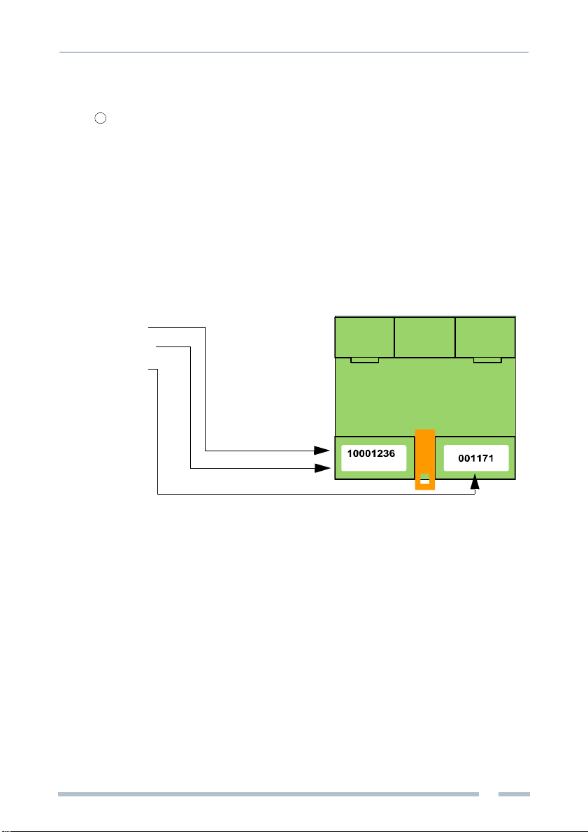
Release
The following information is indicated on the SPI 3 back-panel:
– Article No.
– Release No.
– Serial No.
Implementation guideline
Please procede through the following steps for start-up:
– Mount the SPI 3 (see »Installing the SPI 3« on page 10).
– Connect the SPI 3 to power supply (see »Connecting up the power feed« on
page 10).
– Connect the SPI 3 to the serial field device (see »Connecting up to Sartocheck 4«
on page 11).
– Connect the SPI 3 to the PROFIBUS (see »Connecting up to the PROFIBUS« on
page 11).
– Configure and parameterize the SPI 3 via PROFIBUS configurator (see »Starting
up the SPI 3« on page 13).
6
Release 19

Installing the SPI 3
10
Trebing & Himstedt | SPI 3 | Sartocheck 4
Installing the SPI 3
Mounting the SPI 3
– Place the SPI 3 with the gap onto the top-hat rail and swivel the SPI 3 downward
until the stop lever locks on the top-hat rail.
Warning!
Head space of 5 cm minimum for heat flow is required above and below the
SPI 3.
Dismounting the SPI 3
– Remove the connected supply and signal wires (serial, PROFIBUS, voltage).
– Stick a screwdriver in the slot of the stop lever at the SPI 3.
– Press the screwdriver in the direction of the SPI 3 while at the same time swivelling
the SPI 3 away from the top-hat rail.
Connecting up the power feed
Danger!
Incorrect grounding of the SPI 3 can injure personnel and damage
equipment.
Make sure that the SPI 3 is correctly grounded.
Warning!
Although the SPI 3 is protected against polarity reversal, connecting up the
power feed with incorrect polarity for extended periods can damage the
device. Make sure that the power feed is connected with correct polarity.
– Connect the cables for 24 V power feed, ground and protective ground to the
corresponding screw terminals 24 V, GND and PE.
SPI 3
Top-hat rail
Stop lever

Installing the SPI 3
11
Sartocheck 4 | SPI 3 | Trebing & Himstedt
Connecting up to Sartocheck 4
Note!
To enable communication with the SPI 3, the Sartocheck 4 filter test device
must be version 02.02 or higher.
To ensure that the SPI 3 functions without errors, you should use a screened
cable for connecting to the serial fieldbus device.
– Ensure that the Sub-D connector for the Sartocheck 4 uses the pin assignments
shown in »Technical specifications« on page 17 (connect the cable screen to the
case of the sub-D connector).
– Attach the sub-D connector for the Sartocheck 4 to the serial interface socket on
the SPI 3.
Connecting up to the PROFIBUS
Note!
You should only use commercially available PROFIBUS connectors for
connecting to the bus. We recommend the use ofconnectors from ERNI and
Siemens.
If the SPI 3 is installed at the beginning or end of the PROFIBUS cable
segment, you should use PROFIBUS connectors which contain an integrated
terminating resistor. We recommend using connectors from ERNI and
Siemens.
To ensure that the SPI 3 functions without errors, you must ground the
screen of the PROFIBUS cable.
– Ensure that the PROFIBUS connector uses the pin assignments shown in
»Technical specifications« on page 17.
– Attach the PROFIBUS connector to the PROFIBUS interface socket on the SPI 3
and secure the connector with the retaining screws.
Setting the PROFIBUS address
Note!
The SPI 3 only updates its PROFIBUS address during a restart. Set the
PROFIBUS address on the SPI 3 before switching on the power, or turn off
the power briefly after changing the PROFIBUS address.
You should only use addresses between 01 and 99.
3
2

Installing the SPI 3
12
Trebing & Himstedt | SPI 3 | Sartocheck 4
– The PROFIBUS address is set with the two rotary switches.
Example: In order to set the PROFIBUS address 68, turn the rotary switch for the 10’s
to 6, and the rotary switch for the units to 8.
Bus terminating resistor
Terminations of a PROFIBUS network must each be terminated with a bus
terminating resistor. Use standardized plugs with integrated terminating resistors.
Figure: Bus termination configuration for PROFIBUS (see PROFIBUS Norm)
Note!
Please observe the following when using the depicted passive terminating
resistor: Is the feeding voltage (+5 V) supplied by the device (SPI 3), the
PROFIBUS is shorted via the resistors when the device is disconnected
from voltage. PROFIBUS communication can be interrupted or completely
break down until the device is re-energized.
Use active resistors to avoid this problem, as in this case the terminating
resistors are fed with +5 V and GND independently from the device.
1 390 ΩPull-up resistance from Pin 3 to positive supply voltage at Pin 6
2 220 ΩCable terminating resistor between Pin 3 and Pin 8
3 390 ΩPull-Down resistor from Pin 8 to data reception potential at Pin 5
+5 V DC/DC
(Pin 6) Data+
(Pin 3) Data–
(Pin 8) GND DC/DC
(Pin 5)
[1] [2] [3]

Starting up the SPI 3
13
Sartocheck 4 | SPI 3 | Trebing & Himstedt
Starting up the SPI 3
To start up the SPI 3, you need to configure the device. Configuration is done via
PROFIBUS configurator (PLC programming tool).
– Start the PROFIBUS configurator of the DP master (PLC programming tool).
– Load the »THDP0091.GSD« GSD file for the SPI 3 into the configurator (GSD by
download: www.t-h.de).
– Configure the SPI 3 as described in the configurator online help or user manual.
Select the respective module »SartoCheck« or »SartoCheckExt« for the extended
version 2.0 for configuration. Do not parameterize this module with special user
parameters.
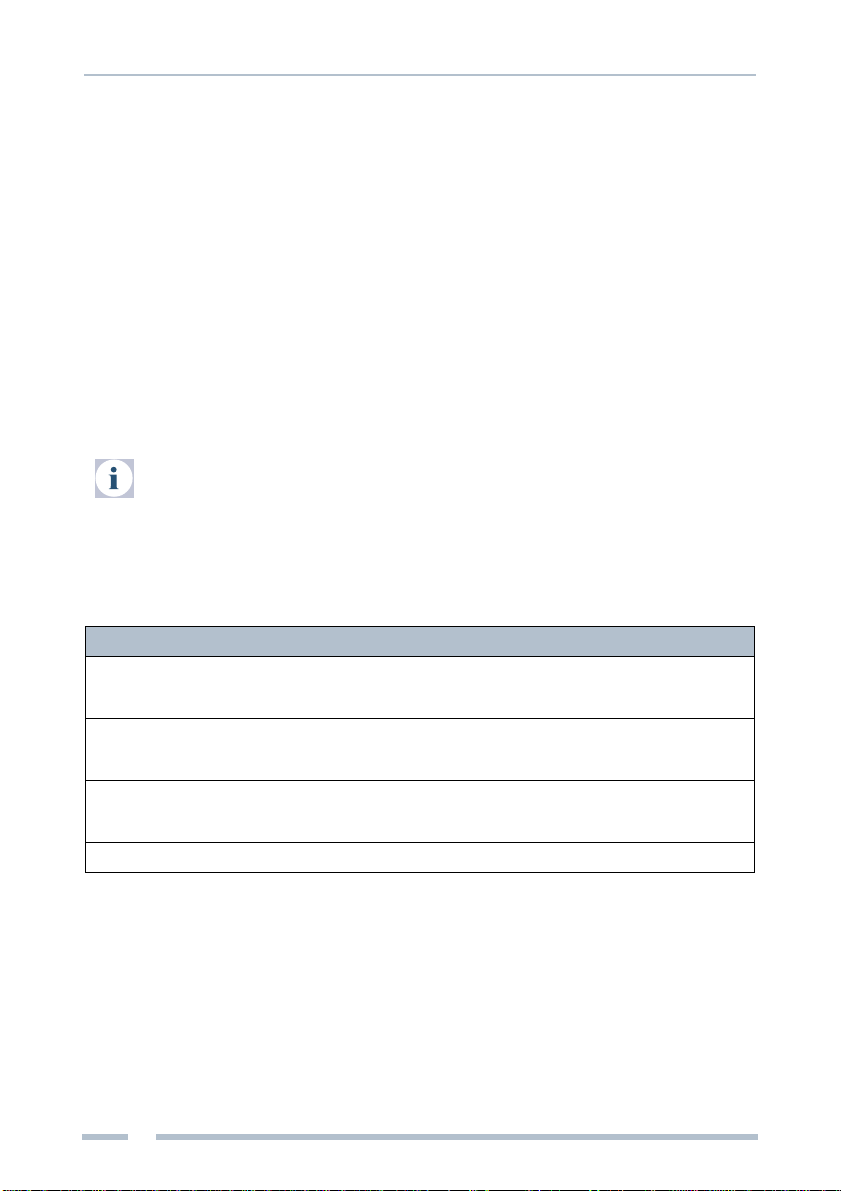
SPI 3 Configuration
During configuration with the PROFIBUS configurator, you are asked to select a
module from the menu. The »SartoCheck« or »SartoCheckExt« module can be used.
Note!
The described module SartoCheck is valid for the SPI 3 release 17 and hig-
her. The described module SartoCheckExt is valid for the SPI 3 release 19
and higher.
Module selection depends on the respective SPI 3 application. All further
modules (not described herein) cannot be used for SPI 3 application with
Sartocheck 4.
Module Name I/O Field Data transfer protocol
SartoCheck 39 Byte Input
21 Byte Output xBPI2
SartoCheckExt 44 Byte Input
21 Byte Output xBPI2

Checking the SPI 3 for correct operation
14
Trebing & Himstedt | SPI 3 | Sartocheck 4
Checking the SPI 3 for correct operation
Several checks should be run before using the SPI 3 for data transfer.
Checking SPI 3 power feed
– At this stage, do not attach either the PROFIBUS interface or the serial interface.
– Switch on the power feed for the SPI 3.
The RUN LED should light continuously. If this is not the case, there is a fault in the
24 V power feed. Refer to »Error diagnosis and remedies« on page 15 for details of
how to locate the fault.
Checking PROFIBUS communication
– Connect up the PROFIBUS interface cable.
– Switch on the power feed for the SPI 3 (RUN-LED lights up).
– Start the DP master which has previously been configured for the SPI 3.
The PB LED should light continuously. If this is not the case, there is an error in the
PROFIBUS communication. Refer to »Error diagnosis and remedies« on page 15 for
details of how to locate the fault.
Checking serial interface communication
– Connect up the PROFIBUS interface cable and the serial interface cable.
– Switch on the power feed for the SPI 3 (RUN-LED lights up).
– Start the DP master which has previously been configured for the SPI 3 (PB-LED
lights up).
The RUN LED should light continuously. If it does not light, or it only flashes, there is
an error in the communication with the serial device. Refer to »Error diagnosis and
remedies« on page 15 for details of how to locate the fault.
If no errors were detected, the SPI 3 is ready for use. During data transfer, the TX or
RX LEDs will flash (see »Indicating elements« on page 9).
Evaluating PROFIBUS diagnosis telegrams
In case of communication failures (PROFIBUS), the SPI3 sends a diagnosis telegram
on DP master request. The diagnosis telegram contains general PROFIBUS
diagnosis data (see PROFIBUS Norm).
You can evaluate the diagnosis telegram through the DP master and/or a PROFIBUS
diagnosis tool (e.g. the PROFIBUS Scope).

Error diagnosis and remedies
15
Sartocheck 4 | SPI 3 | Trebing & Himstedt
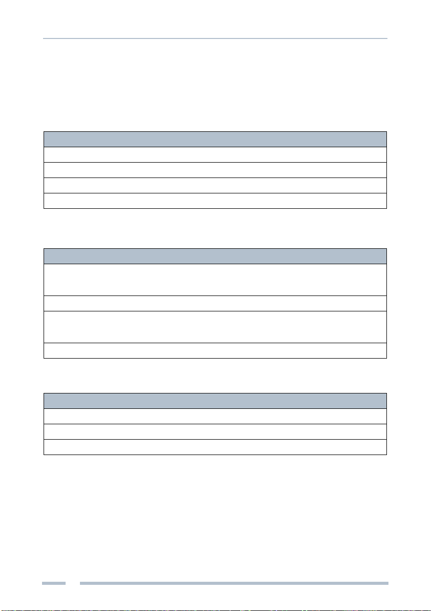
Error diagnosis and remedies
If errors are detected, the pattern of flashing of the PB and RUN LED’s on the SPI 3
can be used for error diagnosis. The LED’s can flash with the following patterns:
Note!
If the PB LED (PROFIBUS) is off, the RUN LED is on continuously and no
longer indicates a valid LED code. Accordingly, the RUN LED can only be
used for diagnosis when the PB LED is lit.
The PROFIBUS diagnosis and error statuses are reset when the error is no
longer present or when the slave gets new parameter and configuration
values.
LED off LED short LED medium LED long LED on
LED off LED is ¾ off ¼ on LED is ½ off ½ on LED is ¼ off ¾ on LED always on
PB LED code Status Significance Remedy
PB LED off Correct data transfer
rate could not be
determined
– No PROFIBUS master in
the network – Connect up the DP master
– Check the wiring
PB LED short DP master available – A master is available but
communication is not
taking place with SPI 3
– Check address setting on
the SPI 3
PB LED
medium Incorrect configuration – Configuration telegram
faulty – Use only the module »Sar-
toCheck« from GSD file
PB LED on Data exchange OK – Data exchange is currently
taking place – SPI 3 working correctly

Error diagnosis and remedies
16 Trebing & Himstedt | SPI 3 | Sartocheck 4
Note!
If errors occur during communication, the DP master runs a PROFIBUS
diagnosis. Evaluation of this diagnosis depends on the used DP master.
When using a bus monitor (e.g. the PROFIBUS Scope), you can also
evaluate diagnosis telegrams.
RUN LED
code Status Significance Remedy
RUN LED off
PB LED off SPI 3 not ready – 24 V supply not present – Check external power
supply
– Check the wiring
RUN LED off
PB LED on Sartocheck 4 is not
connected – no connection to
Sartocheck 4 – Check the wiring to
Sartocheck 4
RUNLED
medium Interface error – Error on xBPI2 protocol – Check version of
Sartocheck 4
(02.02 or higher)
RUN LED on Communication OK – Sartocheck 4 communica-
ting correctly with the SPI 3 – SPI 3 working correctly
Technical specifications
17
Sartocheck 4 | SPI 3 | Trebing & Himstedt
Technical specifications
Electrical data
Nominal supply voltage V DC 24 (20.4…28.8)
Current consumption mA 200
Galvanic isolation, PROFIBUS
interface V DC 500
Ambient conditions
Operating temperature °C 0…60
Case
Protection class IP 20
Dimensions W × H × D mm 75 × 75 × 53
Weight g 136
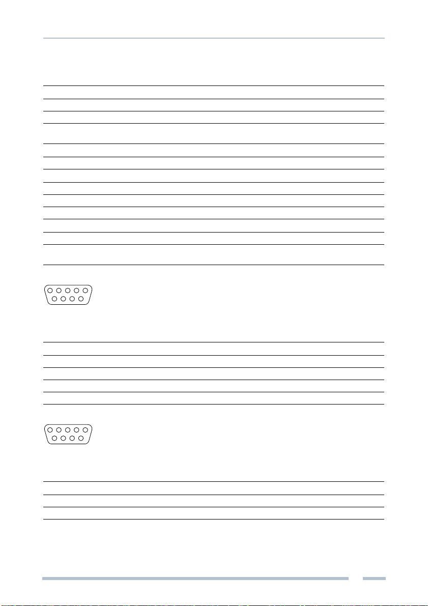
PROFIBUS interface
Interface type RS 485
Data transfer rate Bit/s 9,600; 19,200; 93,750; 187,500; 0.5M; 1.5M; 3M; 6M; 12M,
automatic detection of the data transfer rate
Pin assignment Sub-D connector Pin 1
Pin 2
Pin 3
Pin 4
Pin 5
Pin 6
Pin 7
Pin 8
Pin 9
Screen
Unused
B-line
Request to Send (RTS)
Ground for 5 V (M5)
+5 V (galvanically isolated P5)
Unused
A-line
Unused
Serial interface
Interface type RS 232
Data transfer rate Bit/s 9,600
Data frame Bit 8
Parity odd
Pin assignment Sub-D connector Pin 1
Pin 2
Pin 3
Pin 4
Pin 5
Pin 6
Pin 7
Pin 8
Pin 9
Screen
TXD (out)
RXD (in)
Unused
GND
+5 V
CTS (in)
RTS (out)
Unused
Other
Certifcates CE
Connectable field devices units 1
15
69
15
69
Appendix
18
Trebing & Himstedt | SPI 3 | Sartocheck 4
Appendix
Parameters for Sartocheck 4 test runs
Mapping of serial data from Sartocheck 4 to PROFIBUS DP is structured as follows:
– Data for output:
· common parameters
· test parameters
– Data for input:
· identification
· status data
· test results
Note!
To enable communication with the SPI 3, the Sartocheck 4 filter test device
must be version 02.02 or higher.
Common parameters
Offset Name Internal name Type Unit Visualization
0 Command
(see table 2 on
page 19)
BYTE – Command
1 TestMethod
(see table 4 on
page 19)
eMethod BYTE – Test method
2 TestOptions
(see table 5 on
page 19)
BYTE – –
3 NetVolumeValue vVolumeNet_ml REAL ml –
Table 1: Common parameters

Appendix
19
Sartocheck 4 | SPI 3 | Trebing & Himstedt
Value Bit Description Visualization
0 No change No change
1 Start Filter Test Start filter test
2 Abort Filter Test Abort filter test
3 Clear Alarm Clear alarm
4 Clear Ready Clear ready
Table 2: Common parameters »Command« for SartoCheck
Value Bit Description Visualization
0 No change No change
1 Start Filter Test Start filter test
2 Abort Filter Test Abort filter test
Table 3: Common parameters »Command« for SartoCheckExt
Value Bit Description Visualization
0 DIF Diffusion Test Diffusion Test
1 BPT Bubble Point Test Bubble Point Test
2 WIT Water Intrusion Test
3 PDT Pressure Drop Test
4 WFT Water Flow Test
5 VOL Volume Test
Table 4: Common parameters »TestMethod«
Value Bit Description Visualization
0 Use external Pressure Sensor
1 Use external Venting Mode –
2 WITFillExternal –
Table 5: Common parameters »TestOptions«
Appendix
20
Trebing & Himstedt | SPI 3 | Sartocheck 4
Test parameters
Test parameters depend on the kind of test. Each new test activates the respective
parameter sets. Only parameters required for the selected test are sent.
Diffusion Test – DIF
Bubble Point Test – BPT
Offset Name Internal name Type Unit Visualization
7 DIFTestPressure prPressureTest REAL mbar Test pressure
11 DIFStabTime tTimeStabilization_min WORD min –
13 DIFTestTime tTestDuration_min WORD min Test time
15 DIFDiffusionMax dDiffusionMax_mlmin REAL ml/min Limit value
Table 6: Test parameters DIF
Offset Name Internal name Type Unit Visualization
7 BPTMinFactor cBPMultiplier REAL – –
(Range
0,1…1,0)
11 BPTMaxPressure prBPMax REAL mbar –
15 BPTTestClass
(see table 8 on
page 20)
eTestClass BYTE – Test class
16 BPTMinPressure prBPMin REAL mbar Limit value
Table 7: Test parameters BPT
Value Bit Description Visualization
0 Small Filter Housing Small
1 Standard Filter Housing Standard
2 Large Filter Housing Large
Table 8: Bubble Point Test »BPTestClass«
Other manuals for SPI 3
4
This manual suits for next models
6
Table of contents
Other TREBING + HIMSTEDT Recording Equipment manuals


Popular Recording Equipment manuals by other brands


Iron Ether
Iron Ether Divaricator owner's manual

Roland
Roland SoundCanvas SC-55 owner's guide

Deluge
Deluge Synthstrom Audible instruction manual

Roland
Roland MKS-30 owner's manual

Philips
Philips dynalite AntumbraButton PA6BPA installation instructions

Honeywell
Honeywell IF-LON2 Product Manual and Mounting Instructions