TREND NuAire XBOXER XBC ECOSMART2 Series Installation guide

ErP
COMPLIANT
2015
22. 08. 15. Leaflet Number 671715
XBC 75 & 85 ECOSMART2 (NT) MODELS
NSTALLAT ON, CONTROL DETA LS,
OPERAT NG AND MA NTENANCE

GENERAL INDEX
029 2085 8200
2
PAGE
• HOR ZONTAL UN TS NSTALLAT ON, OPERAT NG & MA NTENANCE NSTRUCT ONS 4 - 12
• VERT CAL UN TS NSTALLAT ON, OPERAT NG & MA NTENANCE NSTRUCT ONS 13 - 19
• DESCR PT ON OF CONTROL 20 - 25
• CONTROL & PCB LAYOUTS 26 - 45
• MA NTENANCE & SERV CE SCHEDULE 46
• CERT F CAT ON 47
XBOXER XBC ECOS ART2 (NT) ODELS

3
nuaire.co.uk
INDEX - INSTALLATION, OPERATING & MAINTENANCE INSTRUCTIONS
FOR XBOXER XBC 75 & 85 ORIZONTAL & VERTICAL UNITS
PAGE
• NTRODUCT ON - XBOXER XBC 75 & 85 HOR ZONTAL (NT) MODELS 4
• XBOXER XBC 75 & 85 HOR ZONTAL (NT) MODELS - ACCESS 5
• DEL VERY & RECE PT OF EQU PMENT, HANDL NG, STORAGE & ERRECT ON & ASSEMBLY 6
• XBOXER XBC 75 & 85 HOR ZONTAL UN T - D MENS ONS 7
• XBOXER XBC 75 & 85 HOR ZONTAL UN T - MOTOR SED DAMPERS 8
• XBOXER XBC 75 & 85 HOR ZONTAL UN T - COMM SS ON NG & SETT NG TO WORK 9
• XBOXER XBC 75 & 85 HOR ZONTAL UN T - SPARE PARTS 10
• XBOXER XBC 75 & 85 HOR ZONTAL UN T - ANC LLAR ES, D MENS ONS & WE GHTS 11 - 12
PAGE
• NTRODUCT ON - XBOXER XBC 75 & 85 VERT CAL (NT) MODELS 13
• XBOXER XBC 75 & 85 VERT CAL (NT) MODELS - ACCESS 14
• XBOXER XBC 75 & 85 VERT CAL - D MENS ONS 15
• XBOXER XBC 75 & 85 VERT CAL UN T - MOTOR SED DAMPERS 15
• XBOXER XBC 75 & 85 VERT CAL UN T - COMM SS ON NG & SETT NG TO WORK 16
• XBOXER XBC 75 & 85 VERT CAL UN T - SPARE PARTS 17
• XBOXER XBC 75 & 85 VERT CAL UN T - ANC LLAR ES, D MENS ONS & WE GHTS 18 - 19
XBOXER XBC ECOS ART2 (NT) ODELS
22. 08. 15. Leaflet Number 671715

029 2085 8200
4
SUPPLY & EXTRACT VENTILATION UNIT
WIT EAT RECOVERY
INSTALLATION, OPERATING & AINTENANCE
INSTRUCTIONS
The EMC Directive
2004/108/EC
The Low Voltage
Directive 2006/95/EC
CODE DESCRIPTION: XBOXER XBC 75 & 85 HORIZONTAL
VENTILATION UNITS
XBC 75 - - LNT - R - WP
|| | | || | |
12 3 4 56 7 8
1. XBOXER XBC Range
2. Counterflow heat exchanger
3. Unit size 75 & 85
4. H = Horizontal
5. type of heater battery:
L = LPHW Heater, N = No Heater
E = Electric Heater
6. Control type:
NT = Ecosmart2 control
ES = Ecosmart control
BC = Basic control
7. R = Opposite configuration
8. WP = Weather roof factory fitted only
Figure 1: Layout Overview of the XBC horizontal unit unit viewed
from above with the lid removed.
INTRODUCTION - XBOXER XBC 75 & 85
ORIZONTAL ECOSMART2 (NT) MODELS
The information contained in this document provides details of
installation, operation and maintenance for installers and users of the
XBOXER XBC75 & 85 Supply and Extract Ventilation Units with eat
Recovery.
This supply and extract air handling unit range comprises an combination
of high efficiency centrifugal fans with EC motors, a counterflow design
plate heat exchanger, filters, optional heaters (LPHW and Electric) and a
casing with high mass acoustic treatment.
The one-piece ventilation unit shall be constructed with double skinned
aluzinc panels on an aluminium Pentapost frame with integral acoustic
mineral fibre ensuring low breakout noise levels. The unit shall incorporate a
high efficiency aluminium counterflow plate heat exchanger matrix with a
thermal efficiency of up to 92%, fitted with a segmented 100% bypass
facility and actuator (patent app.for) operating under automatic control.
A range of matched, side by side internal and external attenuators
(horizontal units) and double deck internal and external attenuators
(Vertical units) with a similar construction method to that of the unit is
available.
eneral information regarding performance and specifications for the
equipment may be obtained from our Technical Literature, and / or project
specific documentation.
XBOXER XBC ECOS ART2 (NT) ODELS
CODE DESCRIPTION: ATCHED SIDE BY SIDE ATTENUATOR
XBC 75 - - SIL900
||| |
123 4
1. XBOXER XBC Range
2. Unit Size 75 & 85
3. H = Horizontal
4. Attenuator SIL900 = 900 mm length
Attenuator SIL900WP = 900 mm length with weather roof

5
nuaire.co.uk
1.0 XBOXER XBC ORIZONTAL UNIT ACCESS
XBOXER XBC ECOS ART2 (NT) ODELS
22. 08. 15. Leaflet Number 671715
Access covers on both
sides of the fan unit.
Access covers on both
sides of the fan unit.
Control cover.
Figure 2: The unit must be installed with at least 650mm clearance from a wall / barrier to gain access from the side. Isolate before removing panels.
Intake
Extract
from room
Exhaust
Supply to
room
G4 Filter
Counterflow
Heat Exchanger
8mm outside dia.
condensate drain.
Condensate pump
fitted as standard
with alarm facility
Control
LPHW or Electric Heater Battery
Figure 3: Horizontal unit access and configuration. Standard (left hand) unit shown.
In this product range, several unique concepts have been
implemented with a view to simplifying the installation design.
1. The unit must be installed with at least 650mm clearance from
a wall / barrier. With this absolute minimum clearance, the unit
may be connected to the power supply and control connection.
1000mm clearance is required to remove the LPHW coil and
electric heater.
2. With this clearance, unit filters may be changed, and the fans
coils, heat exchanger and condensate tray may be inspected and
cleaned if necessary.
3. The LPHW and Electrical heater settings, coil bleed and drain,
and all other control adjustments are similarly accessible.
4. Side access, where possible, is preferred in all cases in terms of
safe working access to the equipment under the CDM regulations.
5. Note however, that access in the situation is difficult and
additional time should be allocated. For convenience it is
preferred that wherever possible, this minimum access provision
is not adopted, and it is recommended that a minimum of
around 600mm clearance (as stated in ADF 2010) is allowed.
6. Where these arrangements are not suitable, the Consultant’s
and Contractor’s project specific requirements will always be
accommodated where possible.

2.0 DELIVERY & RECEIPT OF EQUIPMENT
All equipment is inspected prior to despatch and leaves the factory in
good condition. Upon receipt of the equipment an inspection should be
made and any damage indicated on the delivery note.
Particulars of damage and/or incomplete delivery should be endorsed by
the driver delivering the goods before offloading by the purchaser.
No responsibility will be accepted for damage sustained during the
offloading from the vehicle or on the site thereafter.
All claims for damage and/or incomplete delivery must be reported to
Nuaire within two days of receipt of the equipment.
2.1 OFF LOADING AND ANDLING FROM T E
DELIVERY VE ICLE
The weight of the unit modules and palletised items is displayed on the
unit rating plate or on the packaging. Some of the modules have an
‘uneven’ weight distribution, and this will be indicated by labelling
where appropriate. Ensure that lifting and handling equipment is
adequately rated.
Offloading and positioning of the equipment is the responsibility of the
purchaser.
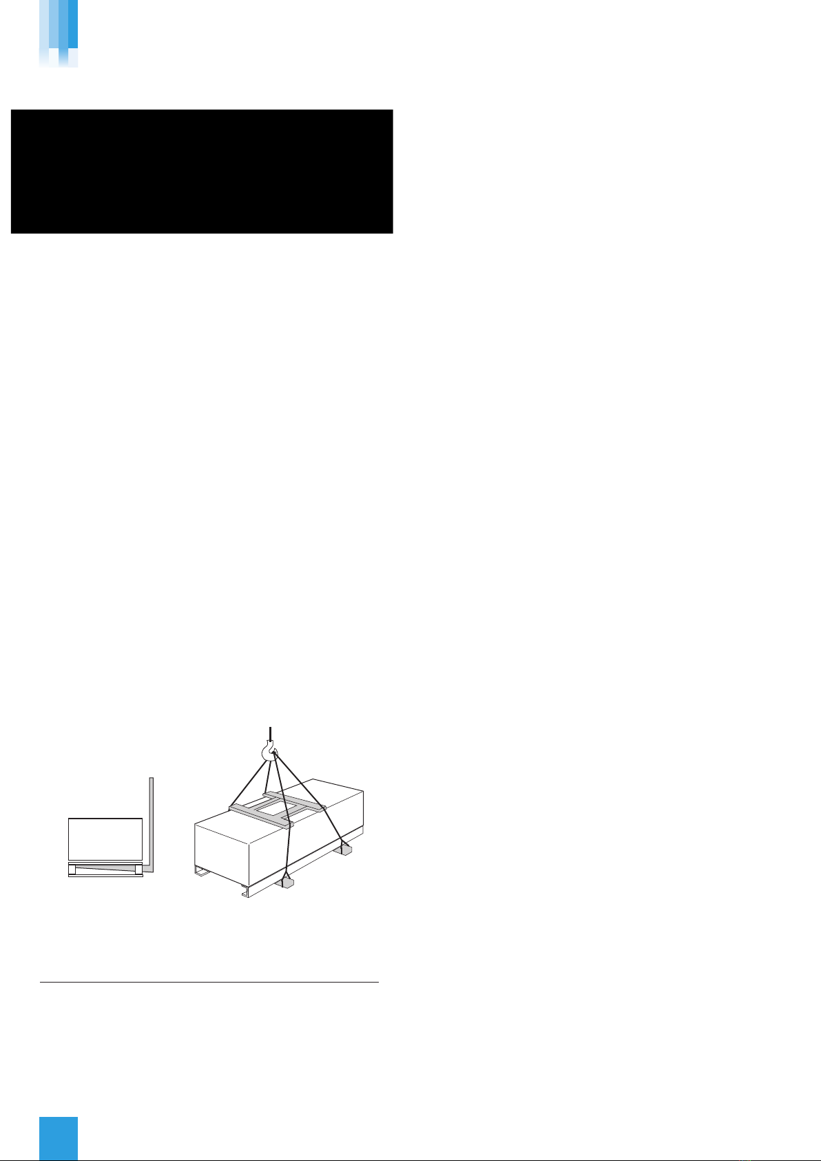
Spreaders should be used when lifting with slings to avoid damage to
the casings. Care must be taken to ensure that slings are correctly
positioned to avoid crushing and twisting of the unit castings.
Where channels and/or support frames are bolted to the underside of
the unit casing, slings or fork-lift arms should be positioned to locate in
the apertures in the channels. If Lifting Eyes have been supplied / fitted
it is recommended that they are used.
CAUTION: The XBC75 & 85 fan units have an uneven weight
distribution, please refer to the unit labelling before Lifting/
offloading the unit.
Figure 4: Lifting.
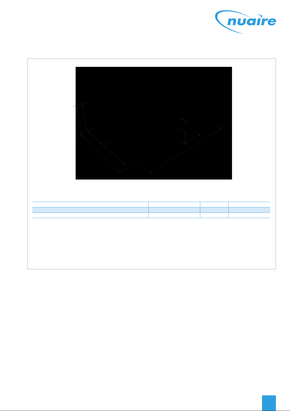
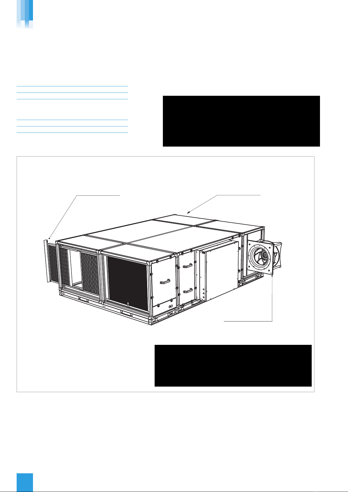
XBOXER XBC unit sections will be delivered to site in the number of
sections shown below.
XBOXER XBC Central Ventilation Unit No. of sections 1
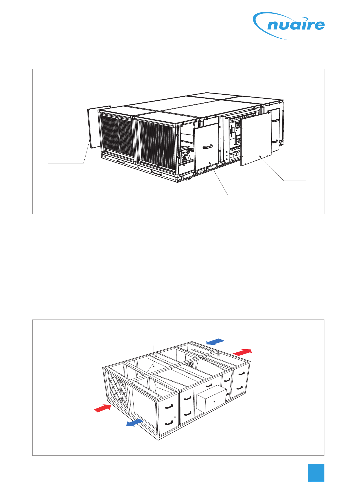
The unit will be labelled with the direction of air flow.
The direction convention must be observed during assembly.
The unit may only be operated in its intended horizontal
installation plane.
The unit must be fully levelled during installation (this is essential to
ensure that condensate drains correctly).
See page 7. for dimensions and weights.
2.3 STORAGE
The equipment must be stored in a dry, internal location. Ductwork
connection apertures shall be sealed against the ingress of dust, water
and vermin. If the storage period is to exceed two months, contact
Nuaire for guidance on the appropriate “mothballing” procedures.
Do not stack units, modules or components.
3.0 ERECTION AND ASSEMBLY
Units must be installed in accordance with good industry practice.
These units may only be mounted horizontally and must be fully
levelled in the horizontal plane.
The units are heavy, and should be mounted using the fixing brackets
supplied or other suitable methods of support.
The supporting structure must be assessed for structural suitability.
If these units are being fitted into a ceiling void a suitable support
structure must be provided under each unit, the baseframe provided is
‘NOT’ suitable for this purpose.
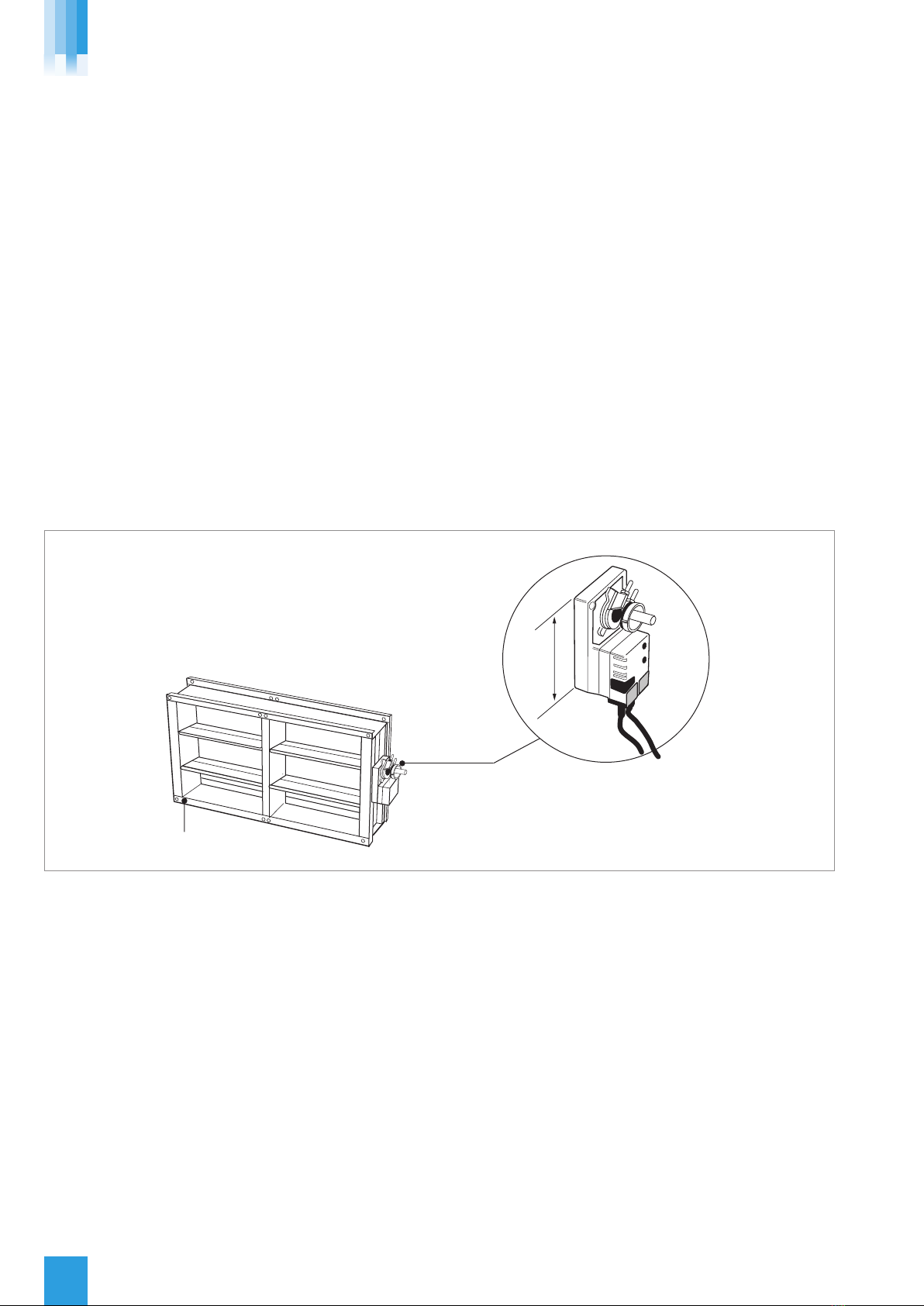
Heat recovery components and modules that incorporate cooling coils
may produce condensation during use.
An insulated drip tray and condensate pump is provided.
The drain connection must be connected to a suitable drainage point.
(See fig 9, page 9 for details).
CONDENSATE PU P ALAR
The condensate pump incorporates an alarm function. If the water level
in the condensate tray exceeds a maximum level (for example, as a
result of the discharge tube becoming blocked or frozen), the alarm
contact will open. This contact is internally connected to the heat
exchanger bypass actuator, and the unit will automatically be placed
into bypass mode, preventing further condensate production. Unit
operation will otherwise be unaffected.
CONDENSATE PU P SPECIFICATION
Maximum flow rate = 50 L/
Maximum head = 20m Vertical, 100m orizontal
Pipe Connection size (Low Pressure Condensate
connection) XBOXER XBC = 8 mm
LPHW Coils, if fitted, are tested during manufacture to 16 Bar (using
dry compressed air). Coil and valve assemblies are similarly tested to
10 Bar. Operation of standard equipment is rated at PN6, if the
intended system requires higher operating pressures; please contact
the Nuaire Technical department for advice.
Electrical connections to the unit shall be made in accordance with the
appropriate product (see below); and installation wiring diagrams, and
shall use appropriately sized and rated cables.
Only the prepared apertures in the unit casing may be used for cable
entry. Do not drill or cut the unit casing for this purpose. Cable access
points are provided at the ends of the control enclosure.
If the control is rotated to aid connection of cables, please ensure that
sufficient flexibility is provided in the final connection run.
NB to avoid conflict with the unit access panels, it is recommended
that electrical and plumbing service connections to the unit are run at
90 degrees to the main air flow axis.
Control circuit connections must be segregated (i.e. routed separately)
from power connections.
The unit rating label shows the maximum electrical load of the
equipment. Connections to the unit may include single phase supply
connections, and a variety of control circuits.
Only the prepared apertures in the unit casing may be used for cable
entry. Do not drill or cut the unit casing for this purpose.
The equipment must be earthed and earth-bonded.
Means of local isolation for maintenance purposes are generally
required (by others). Ensure that all mains connections are isolated.
029 2085 8200
6
Safety first! – before commencing any work ensure:
• That all appropriate risk assesments have been carried
out, and the required safety measures have been taken
• That you understand the work required
• That you are trained and competent to carry it out
XBOXER XBC ECOS ART2 (NT) ODELS
Palletised.
Slings via spreaders fitted to unit with base frame.

7
nuaire.co.uk
XBOXER XBC ECOS ART2 (NT) ODELS
Unit code Unit Dimensions (mm) Control dimensions Unit weights Packed weights
A B C J K M E F G (kg) (kg)
XBC75-H-*** 2800 2126 876 940 740 940 250 730 800 720 902
XBC85-H-*** 2800 2126 876 940 740 940 250 730 800 760 942
The unit is designed for side access as standard and must be installed with a
minimum of clearance of 650mm from a wall or barrier. This will provide access to
filters, coil, fan, heat exchanger, condensate tray and pump.
All models - the weather roof is part of the unit code and is factory fitted only. Example: XBC85-H-LESWP.
*Includes unit and base rail.
Figure 5: Horizontal unit dimensions (mm) and weights (kg).
4.0 XBOXER XBC (NT) ORIZONTAL UNIT DIMENSIONS (MM) AND WEIG TS (KG)
22. 08. 15. Leaflet Number 671715
CK
B
M
J
E
FG
A

029 2085 8200
8
XBOXER XBC ECOS ART2 (NT) ODELS
5.0 XBOXER XBC75 & 85 ORIZONTAL (NT)
MOTORISED DAMPERS
Internal version (example code: XBC75- -MD24V).
If Nuaire matched silencers (example code XBC75-H-SIL900) are being
fitted to the fan unit, the motorised damper (example code
XBC75-H-MD24V) needs to be fitted after the silencers.
This ensures that breakout noise levels are kept to a minimum.
The motorised damper units will be supplied loose and are designed to
fit directly onto the flange connector (by others).
lFully interlocking parallel blades, half inch diameter electroplated
mild steel spindle.
lNylatron bushes and external nylon/aluminium blade inter
connection linkage.
lFitted with Belimo SM24A-S drive open/drive close actuator
complete with switch.
Figure 6: Installing the Motorised Damper.
Motorised Damper
Belimo SM24A-S drive open/drive close
actuator complete with switch.
165mm deep

9
nuaire.co.uk
XBOXER XBC ECOS ART2 (NT) ODELS
22. 08. 15. Leaflet Number 671715
LPHW or electric heater
supply connections Control box
Access to condensate
tray and pump
Condensate drain
connection Ø 8mm push-fit
CONDENSATE ALARM
The condensate pump incorporates an alarm function.
If the water level in the condensate tray exceeds a maximum level (for example, as a result of the discharge tube becoming blocked or
frozen), the alarm contact will open. This contact is internally connected to the heat exchanger bypass actuator, and the unit will
automatically be placed into bypass mode, preventing further condensate production. Unit operation will otherwise be unaffected.
Isolation - Before commencing work make sure
that the unit, switched live and Nuaire control are
electrically isolated from the mains supply.
Figure 7: Customers connections. Control side of horizontal unit showing coil and condensate connections.
6.0 COMMISSIONING & SETTING TO WORK ON
ORIZONTAL UNITS
(Note – not all of the components listed here are necessarily
included with the equipment supplied).
6.1 FILTERS
Remove filter access panels (observe and note airflow direction labels),
inspect filters for contamination with construction debris, replace as
necessary. Replace access panels.
Filter pressure drops will depend on actual flow rate and condition.
Observe and record filter pressure drops after performance
commissioning. Typically, filter “dirty” condition occurs when the initial
filter “clean” readings have been increased by 125Pa. If filter
manometers, pressure switches or indicators have been fitted, they
should be set or adjusted to reflect the commissioned system
operation.
6.2 EATING COILS LP W
Observe the Flow and Return connection labels on the unit.
Drain and bleed valves are located on the coil.
Other valves may be required in the system pipe-work depending on
the installation (by others).
Where the wet system is at risk of frost damage, the addition of a
proprietary anti-freeze solution to the water is recommended.
Note that any frost protection offered by the unit’s integral control
system will not operate if the power supply to the unit is interrupted.
Piped connections should be made to the unit using appropriate
techniques, and all pipework must be independently supported.
No hot work is permitted within one metre of the unit.
Ensure that installed pipework runs do not prevent or restrict access to
the unit at any point.
The completed installation (including the connections within the unit,
as these may be disturbed during installation) shall be pressure tested
to the project engineer’s specification. (A condition of the unit
warranty).
6.3 ELECTRIC EATERS
eater Capacity: XBC75 – 3ph, 12Kw
XBC85 – 3ph, 18Kw
The Electric Heater requires a 3ph supply which is independent from
the main unit supply. Connections to be made through the low level
fixed panel. The Electric Heater may be withdrawn to allow access to
the Heater Controller without the need for wiring to be disconnected
(Ensure the mains supply is isolated before removing any access
panels and any adjustments are made to the Heater Controller).
6.4 FAN SECTIONS
Access to the fan section is via lift off panels. (see fig 7).
For non-Ecosmart units, wiring to the fan motor / unit terminal box
should be mechanically protected and in made in accordance with the
details on the motor name plate and diagram attached to the unit.
With the unit electrically isolated, rotate the fan impeller / drive
manually, checking that it spins freely.
Check all fixings are secure.
Units must not be operated without all access panels in place –
damage to equipment or injury to personnel may result.
Units must not be operated unless control interlocks are in place –
damage to equipment may result.
Test run motor for condition and correct rotation.
Check that the correct current overloads are fitted and that the
current being drawn does not exceed the motor nameplate value.
Excessive current normally indicates that the ductwork system
resistance is different to design.

029 2085 8200
10
XBOXER XBC ECOS ART2 (NT) ODELS
7.0 XBOXER XBC75 & 85 ORIZONTAL (NT)
SPARE PARTS
Ensure correct model is selected:
XBC75 – HORIZONTAL
PART NO. DESCRIPTION
XBC75-H-FILTERKIT Replacement 4 panel filters x 4
776187 Replacement Blower assembly x 1
XBC85 – HORIZONTAL
PART NO. DESCRIPTION
XBC85-H-FILTERKIT Replacement 4 panel filters x 4
776199 Replacement Blower assembly x 1
Supply panel filters.
Remove retaining plate &
slide filters out to replace
Blower assemblies.
Remove 4 x fixings &
slide out to replace
Extract panel filters.
Remove retaining plate &
slide filters out to replace
Figure 8: Replacing filters and blower assembly.
Isolation - Before unit panels are removed make sure
that the unit is isolated.
Caution - Blower Weight
XBC75 - 18kg and XBC85 - 37kg

11
nuaire.co.uk
XBOXER XBC ECOS ART2 (NT) ODELS
8.0 XBOXER XBC75 & 85 ORIZONTAL (NT) ANCILLARY DIMENSIONS (MM) AND WEIG TS
15 241
3
5 3
6
Figure 9: Horizontal Unit ancillary key.
WEAT ER KIT
Ref No. Unit Code Description Dimensions Weight
1 Width eight Length (kg)
XBC75- H- ***WP Unit with weather roof 2000 1001 2800 720
XBC75- H- ***- RWP Unit with weather roof 2000 1001 2800 720
XBC85- H- ***WP Unit with weather roof 2000 1001 2800 760
XBC85- H- ***- RWP Unit with weather roof 2000 1001 2800 760
WEAT ER TERMINAL
Ref No. Unit Code Description Dimensions Weight
2 Width eight Length (kg)
XBC75- H- RT Weather terminal 940 740 700 10
XBC85- H- RT Weather terminal 940 740 700 10
FILTER & MODULE OPTIONS (Side by side and supplied as one piece)
Ref No. Unit Code Description Dimensions Weight
3 Width eight Length (kg)
XBC75- F7B/ 4P- H F7 Bag/ 4 Panel 2000 876 600 115
XBC85- F7B/ 4P- H F7 Bag/ 4 Panel 2000 876 600 115
XBC75- F7B/ 4P- HR F7 Bag/ 4 Panel 2000 876 600 115
XBC85- F7B/ 4P- HR F7 Bag/ 4 Panel 2000 876 600 115
XBC75- 4B- H 4 Bag 2000 1001 600 115
XBC85- 4B- H 4 Bag 2000 1001 600 115
XBC75- 4B- HR 4 Bag 2000 1001 600 115
XBC85- 4B- HR 4 Bag 2000 1001 600 115
XBC75- F7B/ 4P- HWP F7 Bag/ 4 Panel with weather roof 2000 876 600 117
XBC85- F7B/ 4P- HWP F7 Bag/ 4 Panel with weather roof 2000 876 600 117
XBC75- F7B/ 4P- HRWP F7 Bag/ 4 Panel with weather roof 2000 876 600 117
XBC85- F7B/ 4P- HRWP F7 Bag/ 4 Panel with weather roof 2000 876 600 117
XBC75- 4B- HWP 4 Bag with weather roof 2000 1001 600 117
XBC85- 4B- HWP 4 Bag with weather roof 2000 1001 600 117
XBC75- 4B- HRWP 4 Bag with weather roof 2000 1001 600 117
XBC85- 4B- HRWP 4 Bag with weather roof 2000 1001 600 117
22. 08. 15. Leaflet Number 671715

029 2085 8200
12
XBOXER XBC ECOS ART2 (NT) ODELS
8.0 XBOXER XBC75 & 85 ORIZONTAL (NT) ANCILLARY DIMENSIONS (MM) AND WEIG TS
DAMPERS
Ref No. Unit Code Description Dimensions Weight
4 Width eight Length (kg)
XBC75- H- MD24V Motorised dampers 24V for Ecosmart2 models (NT) 840 700 165 20
XBC85- H- MD24V Motorised dampers 24V for Ecosmart2 models (NT) 840 700 165 20
XBC75- H- MD-NC Damper no actuator with extended spindle 840 700 165 20
XBC85- H- MD- NC Damper no actuator with extended spindle 840 700 165 20
2 X MATC ING SILENCERS (Side by side and supplied as one piece)
Ref No. Unit Code Description Dimensions Weight
5 Width eight Length (kg)
XBC75- H- SIL900 Side by side silencer with base frame 2000 876 900 180
XBC85- H- SIL900 Side by side silencer with base frame 2000 876 900 190
XBC75- H- SIL900- WP Side by side silencer with base frame and weather roof 2000 1001 900 180
XBC85- H- SIL900- WP Side by side silencer with base frame and weather roof 2000 1001 900 190
FROST COILS (Side by side and supplied as one piece)
Ref No. Unit Code Description Dimensions Weight
6 Width eight Length (kg)
XBC75- FCL- LNT- H LPHW side by side module with base frame for Ecosmart2 control units (NT) 2000 876 600 113
XBC85- FCL- LNT- H LPHW side by side module with base frame for Ecosmart2 control units (NT) 2000 876 600 113
XBC75- FCL-RNT-H LPHW side by side module with base frame for Ecosmart2 control units (NT) 2000 876 600 113
XBC85- FCL- RNT- H LPHW side by side module with base frame for Ecosmart2 control units (NT) 2000 876 600 113
XBC75- FCE- LNT-H Electric side by side module with base frame for Ecosmart2 control units (NT) 2000 876 600 121
XBC85- FCE- LNT- H Electric side by side module with base frame for Ecosmart2 control units (NT) 2000 876 600 121
XBC75-FCE-RNT-H Electric side by side module with base frame for Ecosmart2 control units (NT) 2000 876 600 121
XBC85-FCE-RNT-H Electric side by side module with base frame for Ecosmart2 control units (NT) 2000 876 600 121
Above is an indicative list of XBC75 & 85 ancillaries, for further details please contact Nuaire.
Note: Codes with ‘R’ i.e. (XBC75- 4B-HR) refer to right hand unit versions.

13
nuaire.co.uk
SUPPLY & EXTRACT VENTILATION UNIT
WIT EAT RECOVERY
INSTALLATION, OPERATING & AINTENANCE
INSTRUCTIONS
The EMC Directive
2004/108/EC
The Low Voltage
Directive 2006/95/EC
CODE DESCRIPTION: XBOXER XBC 75 & 85 VERTICAL
VENTILATION UNITS
XBC 75 - V - LNT - R - WP
|| | | || | |
12 3 4 56 7 8
1. XBOXER XBC Range
2. Counterflow heat exchanger
3. Unit size 75 & 85
4. V = Vertical
5. type of heater battery:
L = LPHW Heater, N = No Heater
E = Electric Heater
6. Control type:
NT = Ecosmart2 control
ES = Ecosmart control
BC = Basic control
7. R = Opposite configuration
8. WP = Weather roof factory fitted only
Figure 10: Layout Overview of the XBC vertical unit viewed with
side panels removed removed.
INTRODUCTION - XBOXER XBC 75 & 85 VERTICAL
ECOSMART2 (NT) MODELS
The information contained in this document provides details of
installation, operation and maintenance for installers and users of the
XBOXER XBC75 & 85 Supply and Extract Ventilation Units with eat
Recovery.
This supply and extract air handling unit range comprises an
combination of high efficiency centrifugal fans with EC motors, a
counterflow design plate heat exchanger, filters, optional heaters (LPHW
and Electric) and a casing with high mass acoustic treatment.
The one-piece ventilation unit shall be constructed with double skinned
aluzinc panels on an aluminium Pentapost frame with integral acoustic
mineral fibre ensuring low breakout noise levels. The unit shall incorporate a
high efficiency aluminium counterflow plate heat exchanger matrix with a
thermal efficiency of up to 92%, fitted with a segmented 100% bypass
facility and actuator (patent app.for) operating under automatic control.
A range of matched, side by side internal and external attenuators
(horizontal units) and double deck internal and external attenuators
(Vertical units) with a similar construction method to that of the unit is
available.
eneral information regarding performance and specifications for the
equipment may be obtained from our Technical Literature, and / or project
specific documentation.
XBOXER XBC ECOS ART2 (NT) ODELS
CODE DESCRIPTION: ATCHED DOUBLE
DECK ATTENUATOR
XBC 75 - V - SIL900
||| |
123 4
1. XBOXER XBC Range
2. Unit Size 75 & 85
3. V = Vertical
4. Attenuator SIL900 = 900 mm length
Attenuator SIL900WP = 900 mm length with weather roof
22. 08. 15. Leaflet Number 671715

029 2085 8200
14
9.0 XBOXER XBC (NT) VERTICAL UNIT ACCESS
XBOXER XBC ECOS ART2 (NT) ODELS
All access panels are located
on one side of the fan unit
Figure 11: The unit must be installed with at least 650mm clearance from a wall / barrier to gain access from the side. Isolate before removing panels.
Side view
Internal control
panel
Intake
Supply
Extract
Discharge
End view
G4 Panel Filter
access
Slide out fans
LPHW or Electric
Heater Battery
8mm outside dia. condensate drain.
Condensate pump fitted as standard
with alarm facility.
Base Frame
(76mm) high
Figure 12: Vertical unit access and configuration. Standard (left hand) unit shown.
In this product range, several unique concepts have been
implemented with a view to simplifying the installation design.
1. The unit must be installed with at least 650mm clearance from
a wall / barrier. With this absolute minimum clearance, the unit
may be connected to the power supply and control connection.
1000mm clearance is required to remove the LPHW coil and
electric heater.
2. With this clearance, unit filters may be changed, and the fans
coils, heat exchanger and condensate tray may be inspected and
cleaned if necessary.
3. The LPHW and Electrical heater settings, coil bleed and drain,
and all other control adjustments are similarly accessible.
4. Side access, where possible, is preferred in all cases in terms of
safe working access to the equipment under the CDM regulations.
5. Note however, that access in the situation is difficult and
additional time should be allocated. For convenience it is
preferred that wherever possible, this minimum access provision
is not adopted, and it is recommended that a minimum of
around 600mm clearance (as stated in ADF 2010) is allowed.
6. Where these arrangements are not suitable, the Consultant’s
and Contractor’s project specific requirements will always be
accommodated where possible.
Note: Unit must be isolated before panels are removed.

15
nuaire.co.uk
XBOXER XBC ECOS ART2 (NT) ODELS
Unit code Unit Dimensions (mm) Control dimensions Unit weights Packed weights
A B C J K M E F G (kg) (kg)
XBC75-V-*** 2500 954 1416* 610 894 60 954 2500 630 730
XBC85-V-*** 3000 1000 1676* 940 740 65 1000 3000 780 880
Figure 13: Vertical unit dimensions (mm) and weights (kg).
10.0 XBOXER XBC (NT) VERTICAL UNIT DIMENSIONS (MM) AND WEIG TS (KG)
22. 08. 15. Leaflet Number 671715
The unit is designed for side access as standard and must be installed with
a minimum of clearance of 650mm from a wall or barrier. This will provide
access to filters, coil, fan, heat exchanger, condensate tray and pump.
All models - the weather roof is part of the unit code and is factory fitted
only. Example: XBC85-V-LESWP.
*Includes unit and base rail.
If Nuaire matched silencers (example code XBC75-H-SIL900) are being
fitted to the fan unit, the motorised damper (example code
XBC75-V-MD24V) needs to be fitted after the silencers.
This ensures that breakout noise levels are kept to a minimum.
The motorised damper units will be supplied loose and are designed to
fit directly onto the flange connector (by others).
lFully interlocking parallel blades, half inch diameter electroplated
mild steel spindle.
lNylatron bushes and external nylon/aluminium blade inter
connection linkage.
lFitted with Belimo SM24A-S drive open/drive close actuator
complete with switch.
Figure 14: Installing the Motorised Damper.
Motorised Damper
Belimo SM24A-S drive open/drive close
actuator complete with switch.
165mm deep
11.0 XBOXER XBC75 & 85 VERTICAL (NT) MOTORISED DAMPERS
Internal version (example code: XBC75-V-MD24V).

029 2085 8200
16
XBOXER XBC ECOS ART2 (NT) ODELS
Isolation - Before commencing work make sure
that the unit, switched live and Nuaire control are
electrically isolated from the mains supply.
Figure 15: Customers connections. Control side of horizontal unit showing coil and condensate connections.
12.0 COMMISSIONING & SETTING TO WORK
ON VERTICAL UNITS
(Note – not all of the components listed here are necessarily
included with the equipment supplied).
12.1 FILTERS
Remove filter access panels (observe and note airflow direction labels),
inspect filters for contamination with construction debris, replace as
necessary. Replace access panels.
Filter pressure drops will depend on actual flow rate and condition.
Observe and record filter pressure drops after performance
commissioning. Typically, filter “dirty” condition occurs when the initial
filter “clean” readings have been increased by 125Pa. If filter
manometers, pressure switches or indicators have been fitted, they
should be set or adjusted to reflect the commissioned system
operation.
12.2 EATING COILS LP W
Observe the Flow and Return connection labels on the unit.
Drain and bleed valves are located on the coil.
Other valves may be required in the system pipe-work depending on
the installation (by others).
Where the wet system is at risk of frost damage, the addition of a
proprietary anti-freeze solution to the water is recommended.
Note that any frost protection offered by the unit’s integral control
system will not operate if the power supply to the unit is interrupted.
Piped connections should be made to the unit using appropriate
techniques, and all pipework must be independently supported.
No hot work is permitted within one metre of the unit.
Ensure that installed pipework runs do not prevent or restrict access to
the unit at any point.
The completed installation (including the connections within the unit,
as these may be disturbed during installation) shall be pressure tested
to the project engineer’s specification. (A condition of the unit
warranty).
12.3 ELECTRIC EATERS
eater Capacity: XBC75 – 3ph, 12Kw
XBC85 – 3ph, 18Kw
The Electric Heater requires a 3ph supply which is independent from
the main unit supply. Connections to be made through the low level
fixed panel. The Electric Heater may be withdrawn to allow access to
the Heater Controller without the need for wiring to be disconnected
(Ensure the mains supply is isolated before removing any access
panels and any adjustments are made to the Heater Controller).
12.4 FAN SECTIONS
Access to the fan section is via lift off panels. (see fig 15).
For non-Ecosmart units, wiring to the fan motor / unit terminal box
should be mechanically protected and in made in accordance with the
details on the motor name plate and diagram attached to the unit.
With the unit electrically isolated, rotate the fan impeller / drive
manually, checking that it spins freely.
Check all fixings are secure.
Units must not be operated without all access panels in place –
damage to equipment or injury to personnel may result.
Units must not be operated unless control interlocks are in place –
damage to equipment may result.
Test run motor for condition and correct rotation.
Check that the correct current overloads are fitted and that the
current being drawn does not exceed the motor nameplate value.
Excessive current normally indicates that the ductwork system
resistance is different to design.
LPHW or electric heater
supply connections Control box
Access to condensate
tray and pump
Condensate drain
connection Ø 8mm push-fit
Fixed panel for
customer connections
CONDENSATE ALARM
The condensate pump incorporates an alarm function.
If the water level in the condensate tray exceeds a maximum level (for example, as a result of the discharge tube becoming blocked or
frozen), the alarm contact will open. This contact is internally connected to the heat exchanger bypass actuator,
and the unit will automatically be placed into bypass mode, preventing further condensate production. Unit operation will otherwise be
unaffected.

17
nuaire.co.uk
XBOXER XBC ECOS ART2 (NT) ODELS
22. 08. 15. Leaflet Number 671715
13.0 XBOXER XBC75 & 85 VERTICAL (NT)
SPARE PARTS
Ensure correct model is selected:
XBC75 – VERTICAL
PART NO. DESCRIPTION
XBC75-V-FILTERKIT Replacement 4 panel filters x 4
776187 Replacement Blower assembly x 1
XBC85 – VERTICAL
PART NO. DESCRIPTION
XBC85-V-FILTERKIT Replacement 4 panel filters x 4
776188 Replacement Blower assembly x 1
Extract panel filters.
Remove retaining plate &
slide filters out to replace
Supply panel filters.
Remove retaining plate &
slide filters out to replace
Blower assemblies.
Remove 4 x fixings &
slide out to replace
Figure 16: Replacing filters and blower assembly.
Isolation - Before unit panels are removed make sure
that the unit is isolated.
Caution - Blower Weight
XBC75 - 18kg and XBC85 - 37kg

029 2085 8200
18
XBOXER XBC ECOS ART2 (NT) ODELS
14.0 XBOXER XBC75 & 85 VERTICAL (NT) ANCILLARY DIMENSIONS (MM) AND WEIG TS
Figure 17: Vertical Unit ancillary key.
3
1
5
2563
4
5
1
WEAT ER KIT
Ref No. Unit Code Description Dimensions Weight
1 Width eight Length (kg)
XBC75- V- ***WP Unit with weather roof 954 1476 2500 630
XBC75- V- ***- RWP Unit with weather roof 954 1476 2500 630
XBC85- V- ***WP Unit with weather roof 1000 1741 3000 780
XBC85- V- ***- RWP Unit with weather roof 1000 1741 3000 780
WEAT ER TERMINAL
Ref No. Unit Code Description Dimensions Weight
2 Width eight Length (kg)
XBC75- RT Weather terminal for vertical unit 842 570 610 8
XBC85- RT Weather terminal for vertical unit 940 740 700 10
FILTER & MODULE OPTIONS (Double deck and supplied as one piece)
Ref No. Unit Code Description Dimensions Weight
3 Width eight Length (kg)
XBC75- F7B/ 4P F7 Bag/ 4 Panel 954 1416 600 90
XBC85- F7B/ 4P F7 Bag/ 4 Panel 1000 1676 600 105
XBC75- F7B/ 4P- R F7 Bag/ 4 Panel 954 1416 600 90
XBC85- F7B/ 4P- R F7 Bag/ 4 Panel 1000 1676 600 105
XBC75- 4B 4 Bag 954 1416 600 90
XBC85- 4B 4 Bag 1000 1676 600 105
XBC75- 4B- R 4 Bag 954 1416 600 90
XBC85- 4B- R 4 Bag 1000 1676 600 105
XBC75- F7B/ 4P- WP F7 Bag/ 4 Panel with weather roof 954 1476 600 92
XBC85- F7B/ 4P- WP F7 Bag/ 4 Panel with weather roof 1000 1741 600 107
XBC75- F7B/ 4P- RWP F7 Bag/ 4 Panel with weather roof 954 1476 600 92
XBC85- F7B/ 4P- RWP F7 Bag/ 4 Panel with weather roof 1000 1741 600 107
XBC75- 4B- WP 4 Bag with weather roof 954 1476 600 92
XBC85- 4B- WP 4 Bag with weather roof 1000 1741 600 107
XBC75- 4B- RWP 4 Bag with weather roof 954 1476 600 92
XBC85- 4B- RWP 4 Bag with weather roof 1000 1741 600 107

19
nuaire.co.uk
XBOXER XBC ECOS ART2 (NT) ODELS
22. 08. 15. Leaflet Number 671715
14.0 XBOXER XBC75 & 85 VERTICAL (NT) ANCILLARY DIMENSIONS (MM) AND WEIG TS
DAMPERS
Ref No. Unit Code Description Dimensions Weight
4 Width eight Length (kg)
XBC75- V- MD24V Motorised dampers 24V for Ecosmart2 models (NT) 620 560 165 14
XBC85- V- MD24V Motorised dampers 24V for Ecosmart2 models (NT) 840 700 165 20
XBC75- V- MD-NC Damper no actuator with extended spindle 620 560 165 14
XBC85- V- MD- NC Damper no actuator with extended spindle 840 700 165 20
2 X MATC ING SILENCERS (Double deck and supplied as one piece)
Ref No. Unit Code Description Dimensions Weight
5 Width eight Length (kg)
XBC75- V- SIL900 Double deck silencer with base frame 954 1416 900 180
XBC85- V- SIL900 Double deck silencer with base frame 1000 1676 900 200
XBC75- V- SIL900- WP Double deck silencer with base frame and weather roof 954 1476 900 185
XBC85- V- SIL900- WP Double deck silencer with base frame and weather roof 1000 1741 900 205
FROST COILS (Double deck and supplied as one piece)
Ref No. Unit Code Description Dimensions Weight
6 Width eight Length (kg)
XBC75- FCL- LNT- V LPHW double deck module with base frame for Ecosmart2 models (NT) 954 1416 600 115
XBC85- FCL- LNT- V LPHW double deck module with base frame for Ecosmart2 models (NT) 1000 1676 600 120
XBC75- FCL- RNT-V LPHW double deck module with base frame for Ecosmart2 models (NT) 954 1416 600 115
XBC85- FCL-RNT- V LPHW double deck module with base frame for Ecosmart2 models (NT) 1000 1676 600 120
XBC75- FCE- LNT-V Electric double deck module with base frame for Ecosmart2 models (NT) 954 1416 600 100
XBC85- FCE- LNT- V Electric double deck module with base frame for Ecosmart2 models (NT) 1000 1676 600 105
XBC75- FCE-RNT- V Electric double deck module with base frame for Ecosmart2 models (NT) 954 1416 600 100
XBC85- FCE- RNT-V Electric double deck module with base frame for Ecosmart2 models (NT) 1000 1676 600 105
Above is an indicative list of XBC75 & 85 ancillaries, for further details please contact Nuaire.
Note: Codes with ‘R’ i.e. (XBC75- 4B-R) refer to right hand unit versions.

029 2085 8200
20
XBOXER XBC ECOS ART2 (NT) ODELS
INDEX - DESCRIPTION OF CONTROL
PAGE
• GENERAL 21
• CONTROLLABLE TEMS 21
• ENABLE S GNAL 21
• OCCUPANCY CONTROL 21
• BOOST 21
• TR CKLE MODE 22
• CO2CONTROL 22
• SUPPLY TEMPERATURE CONTROL 22
• FROST PROTECT ON 22
• N GHT COOL NG / SUMMER FREE COOL NG 22
• ALARMS 22
• THERMAL TR P 22
• SET PO NTS 23 / 24
• COMPAT BLE CONTROL OPT ONS 25
This manual suits for next models
2
Table of contents
Popular Fan manuals by other brands

Americ Corporation
Americ Corporation VAF-3000 owner's manual

Craftmade
Craftmade American Tradition AT52ET Specifications

Paris Rhone
Paris Rhone PE-TF005 user manual

NuTone
NuTone QuieTTest Combination Fan/Light QT140L installation instructions

Fanelite
Fanelite PRICKLY 38YFT-7057M operating manual

Hunter
Hunter 23683 Parts guide

Airius
Airius SAPPHIRE Series PRODUCT INFORMATION & INSTALLATION GUIDE

Manutan
Manutan A154366 user guide

LMF Clima
LMF Clima HPX Series Installation, operation & maintenance manual

Helios
Helios B KLG Series Installation and operating instructions

Klarstein
Klarstein 10028293 manual

Perel
Perel CFANFS45N user manual