SDU-xciteInstallationInstructionsTG200643 Issue 1/E 20/11/06 7
Installation Instructions - Sheet n SDU-xcite
If need for temporary Unrestricted mode for Commissioning or need for Manual reset
(e.g. after multiple mode changes as in step 14)
edoMteSegaP emoH
egaP
mralA
goL
0detcirtsernUoNseY
1detcirtsernUseY seY
2detcirtsernUoNoN
3detcirtsernUseY oN
4detcirtseRoNoN
5detcirtseRseY oN
6detcirtseRoNoN
7detcirtseRseY oN
8yrotceriDdnayalpsiDoNoN
9yrotceriDdnayalpsiDseY oN
01yrotceriDdnayalpsiDoNoN
11yrotceriDdnayalpsiDseY oN
Set up Parameters
16
Set up the following parameters in IQ3xcite using SDU:
Knobs
Switches
Time Zone Day of week (1 to 7)
Occupation Change Time (1 to n) hours, minutes, status
Exception (1 to n) Use (next, free, every)
Start date Stop date
Occupation Change Time (1 to n) hours, minutes, status
Time hrs, minutes, day of month, month, year
daylight saving on, day of month, month
daylight saving off, day of month, month
SDU Data Sheet
TA200559
If required
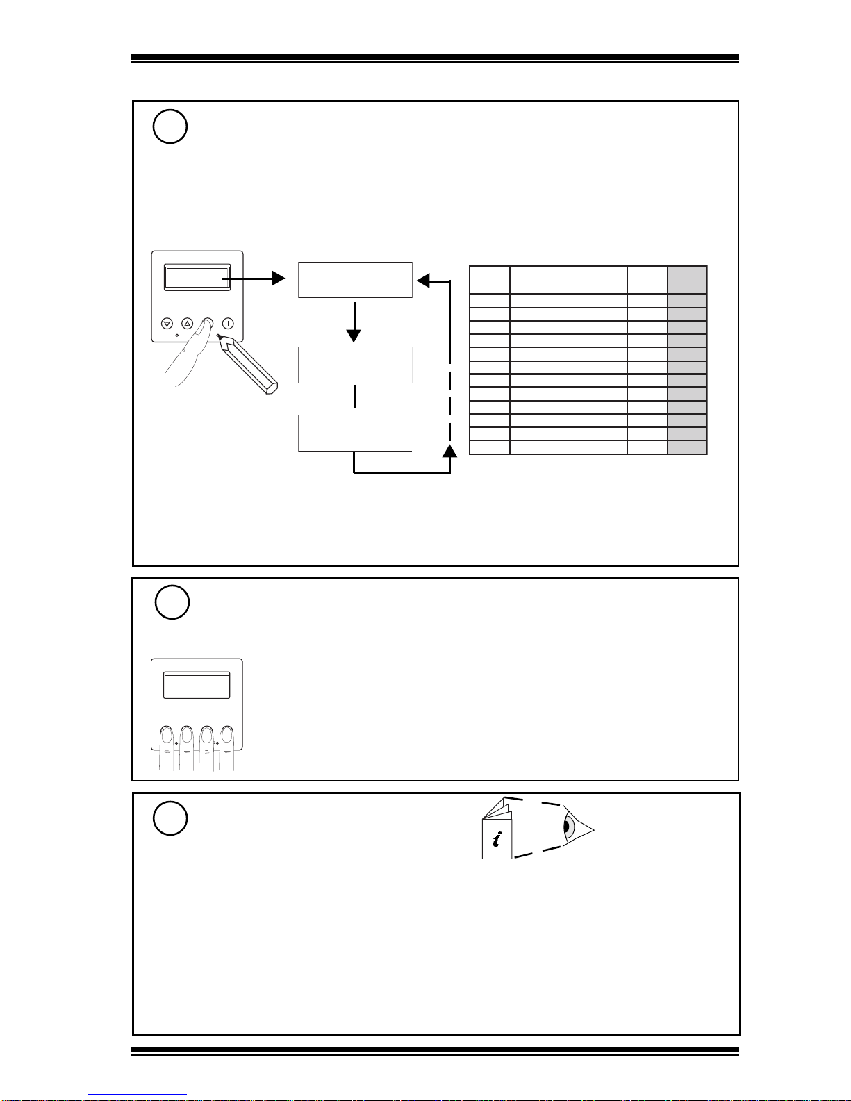
Set SDU Mode
14
3Installation(Continued)
If required
S P E N G
1 2 3 4
S e n s o r 1
F l o o r 1 S p a c e T e m p
2 0 . 3 D e g C
Display Mode = 1
S e n s o r 1
F l o o r 1 S p a c e T e m p
2 0 . 3 D e g C
Display Mode = 11
Default - Display Mode 2:
Unrestricted, no home page, alarm log disabled
SettoMode0or1toenablealarmlogifIQ3 >=V1.2
Notethat if the home page isenabled, the controllers identifier [R(D)] should beset up, otherwise the
first line of the home page will show the label of the previous item displayed.
aRemove front cover - see step 3
bSet mode
cReplace front cover - see step 9
Engineering Resets
15
S P E N G
1 2 3 4
Hold 5 secs - 10 secs Tempory Unrestricted Mode - returns to previous
mode 20 seconds after last key press.
Hold 10 secs or greater Manual Reset
NotethatifalarmlogisenabledorIQ3 <V1.2
the display will indicate ‘None’