VSD2H Variable Speed Drives Data Sheet TA201104 Issue 3, 08-Oct-2013 7
Data Sheet VSD2H
FIRMWARE
Full details of the rmware are diven in the VSD2H Application
Manual TE201103.
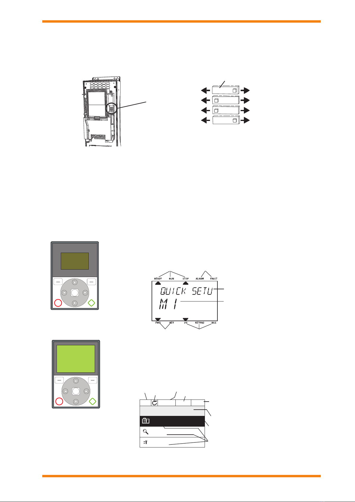
Quick Setup
On initial power up, the Startup Wizard will prompt for:
Language
Daylight saving (Russia/US/EU/off)
Time, Day, Year
Run Startup Wizard (Y/N)
If yes:
Process (pump or fan)
Motor Nominal Speed (range 24 to 19200 rpm)
Motor Nominal Current (range depends on unit)
There are other mini-wizards that can be used for setting the
following:
PID: Three term control for motor or external device by
way of I/O.
Pump and Fan Cascade: Cascade control of several
pumps or fans.
Resonance Sweep: For elimination of possible
resonance points in the system.
The Quick Setup menu, mentioned above, enables access to
the parameters most commonly used during installation and
commissioning including access to the Startup, PID, and Pump
and Fan Cascade wizards
Uninterruptible Operation and Energy Saving
Over temperature ride-through: Automatically adjusts
switching frequency and/or speed of the motor to adapt to
unusual increase in ambient. Benet: Uninterruptible operation.
Over temperatureride-through: Automatically adjusts
switching frequency and/or speed of the motor to adapt to
unusual increase in ambient. Benet: Uninterruptible operation.
RTO –Ramp Time Optimizer When problematic areas are
identied in acceleration or deceleration the drive automatically
expands the times needed for this to avoid mechanical stress
to the system. Benet: Decreased mechanical stress to the
system.
Trip free output switching Ensures trip free operation
when an output switch (e.g. safety switch) is operated between
the motor and the VSD. Truly intelligent and highly reliable
function to ensure better functionality than with any other VSD.
Benet: Uninterruptible operation.
Energy Saving function “Flux Optimization”: Flux
Optimization automatically minimizes energy consumption.
Benet: Even 5% increase in energy savings.
Congurable Auto reset function: Auto restart function can
be congured to make VSD restart automatically once fault is
addressed. Benet: Uninterruptible operation.
VFD and Motor Control
Single input control: Analog signal rising edge can be used to
start the device without additional start signal to a digital input.
Benet: Cost and time savings.
Flying start: Ability to get an already spinning fan under speed
control. Benets: Improved performance·. Very important in
clean room production.
Automatic torque boost function: Boosts initial voltage to
start high inertia fans. Benet: Avoids tripping and enables
smooth starts also to high inertia loads.
High Switching Frequency: The VSD2H is capable of
providing the maximum power with high switching frequency.
Benet: Low audible noise from the motor.
Prohibit frequency: Overriding the critical frequencies to
avoid resonance. Can be set with the help of resonance sweep
wizard. Benet: Elimination of resonance.
Maintenance counters/alarms: The drive can be programmed
to notify on upcoming maintenance for the system or the drive
itself. Benet: Reliability
Temperature-controlled fans: Fan stops operating when
not needed Benets: Less audible noise from the VSD itself.
Energy savings.
Advanced HVAC Control
Time based control: With the help of the real time clock and
calendar functionality the drive can be programmed to perform
functions based on time. Benets: Cost savings. Flexibility.
Inbuilt PID controller: Normal and Inverse Regulation, Delta P
regulation with 2 standard pressure transmitters, Feed forward
control, Less wiring since sensor normally close to inverter.
Benet: Cost saving. Faster response to process closed loop.
Sleep Mode: Shutting down the motor, when no demand.
Benet: Energy savings.
Pressure loss compensation: For compensating e.g. wrongly
placed sensor in the system. Benet: Time and cost saving.
Pump Soft ll: Feature to prevent the overpressures when
lling empty pipe work. Benet: Longer lifetime of the system.
Fire override mode: Keeps fan/pump running in case of re.
Benet: Legal requirement.
Pump and Fan Cascade control with full auto-change:
Controls total pumping system with several parallel pumps by
equally sharing the load. Also the master pump can be included
in auto-change loop. Benets: Longer lifetime of the system.·
Cost savings.
SOFTWARE
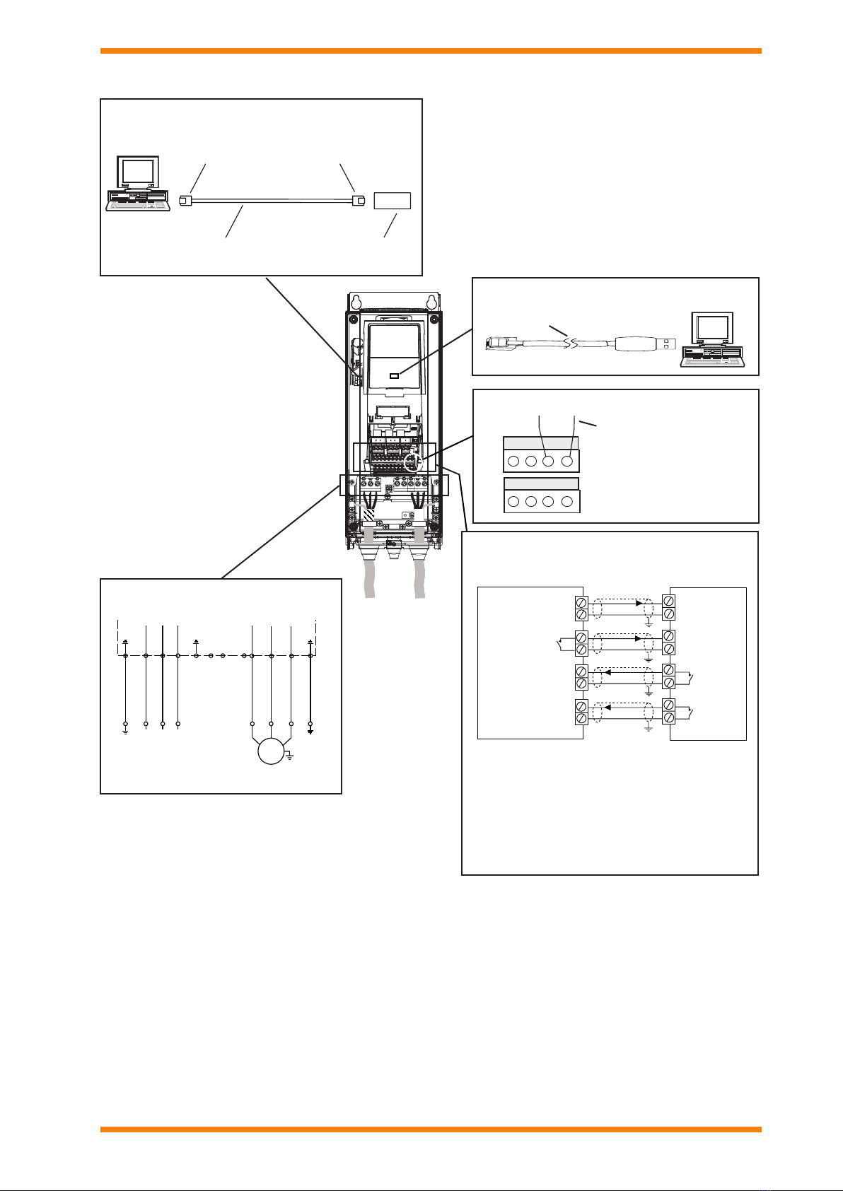
Windows based PC utility tools are available for making the use
of the Trend VSD2H as easy and convenient as possible. The
tools facilitate installation, commissioning, and maintenance.
The software is self-documenting from its integral help le. The
minimum requirement for using the software is a PC and a USB
to RS485 interface cable (e.g. ACC/VSD2H/USB-PC/CABLE,
3 m), to be connected to the RS485 terminal behind the control
panel. The software tools are available as a download from
Partnernet.
Drive Care PC Tool: The Drive Care tool is easy-to-use
commissioning software for the control of the VSD2H. It enables
the following:
Setting up parameters with the PC
Saving Settings to the PC
Creating commissioning documentation
Comparing paramters settings
Monitoring view with graphics
Diagnostics
Controlling the drive from the PC
This tool also includes the Loader tool which enables the
downloading of rmware or applications.
Note that the drive conguration can be loaded from one drive
into the advanced commissioning keypad (ACC/VSD2H/
GRAPHIC DISPLAY), and downloaded into another drive.