TRENDnet TV-IP100 - DATA SHEETS User manual
1

2
TABLE OF CONTENTS
ABOUT THIS GUIDE.....................................................................5
INTRODUCTION .............................................................................6
SYSTEM REQUIREMENT............................................................7
INTERNET CAMERA ............................................................................. 7
Network:......................................................................................... 7
Recommended PC or Notebook to Access the Internet Camera.... 7
FEATURES AND BENEFITS......................................................9
SIMPLE TO USE ................................................................................... 9
SUPPORT VARIETY OF PLATFORMS ................................................... 10
WEB CONFIGURATION....................................................................... 10
REMOTE UTILITY .............................................................................. 10
BROAD RANGE OF APPLICATIONS ..................................................... 11
PHYSICAL DESCRIPTION........................................................12
FRONT PANEL.................................................................................... 12
Power LED .................................................................................. 13
Link LED...................................................................................... 13
REAR PANEL ..................................................................................... 14
Network Cable Connector ........................................................... 14
DC Power Connector................................................................... 14
Reset Button................................................................................. 15
TOP PANEL ........................................................................................ 16
Screw Hole................................................................................... 16
BOTTOM PANEL................................................................................. 17
Screw Hole................................................................................... 17
UNPACKING THE INTERNET CAMERA............................18
CONNECTING THE INTERNET CAMERA TO THE CAMERA STAND........ 19
3
HARDWARE INSTALLATION..................................................20
1CONNECT AN ETHERNET CABLE ..................................................... 20
2ATTACH THE EXTERNAL POWER SUPPLY......................................... 21
SECURITY........................................................................................22
SOFTWARE INSTALLATION...................................................23
WEB CONFIGURATION....................................................................... 23
MAIN MENU IMAGE .......................................................................... 25
SYSTEM ADMINISTRATION ................................................................ 26
SYSTEM ADMINISTRATION ................................................................ 26
System Administration – System .................................................. 26
System Administration - Image.................................................... 33
System Administration - Users..................................................... 35
System Administration – DateTime.............................................. 37
System Administration – Upload................................................. 39
System Administration – E-mail................................................... 42
System Administration - Information........................................... 44
System Administration - Tools..................................................... 45
VIEW IMAGE –ACTIVEXMODE ........................................................ 46
VIEW IMAGE –JAVA MODE............................................................... 48
INTERNET CAMERA APPLICATION...................................50
APPLICATIONS................................................................................... 51
INTERNET CAMERA APPLICATION DIAGRAMS................................... 52
Home Applications....................................................................... 52
SOHO Applications...................................................................... 53
IPVIEW SE APPLICATION.......................................................54
INSTALLATION................................................................................... 54
GETTING STARTED....................................................................60
IPVIEW SE ........................................................................................ 60
IPView SE control panel.............................................................. 61
Minimize ...................................................................................... 62
Exit............................................................................................... 62

4
Play.............................................................................................. 62
Scan ............................................................................................. 62
Combine....................................................................................... 62
About............................................................................................ 62
HOW TO ADD A CAMERA................................................................... 63
Add Camera................................................................................. 63
HOW TO CHANGE CAMERA ............................................................... 69
Assign IP of New Camera............................................................ 69
HOW TO CONNECT /DISCONNECT THE IMAGE................................... 70
Connect the Image....................................................................... 70
Disconnect the Image................................................................... 72
HOW TO DELETE A CAMERA ............................................................. 73
Erase Camera.............................................................................. 73
EXTRA INFORMATION........................................................................ 74
Extra Information ........................................................................ 74
HOW TO ADJUST THE PROPERTY SETTING......................................... 75
System Configure......................................................................... 75
Camera Configure ....................................................................... 77
Camera Setting ............................................................................ 77
Motion Setting.............................................................................. 78
Update Firmware......................................................................... 80
HOW TO ADJUST THE RECORDING SETTING ...................................... 81
Motion Record............................................................................. 81
Schedule Record .......................................................................... 81
Manual Record ............................................................................ 81
APPENDIX .......................................................................................82
AFREQUENTLY ASKED QUESTIONS .................................................. 82
BPING YOUR IP ADDRESS............................................................... 85
CTROUBLE SHOOTING ...................................................................... 86
DTIME ZONE TABLE......................................................................... 90
EXPLUG CONTROL INSTALLATION ................................................... 92
FADJUST INTERNET CAMERA FOCUS................................................ 96
GSPECIFICATION .............................................................................. 97
HGLOSSARY OF TERMS ................................................................... 100
5
ABOUT THIS GUIDE
This manual describes Internet Camera, including a description of
the features, as well as the installation procedures and web
configuration. Included in the manual are the operating
procedures for the IPView SE application.

6
1
INTRODUCTION
Thank you for the purchase of the Internet Camera connecting
directly to an Ethernet or Fast Ethernet. It is different from the
conventional PC Camera, the Internet Camera is a standalone
system with built-in CPU and web-based solutions providing a
low cost solution that can transmit high quality video images for
monitoring. The Internet Camera can be managed remotely,
accessed and controlled from any PC/Notebook over the Intranet
or Internet via a web browser. The simple installation procedures
and web-based interface offers easy integration to your network
application environments coupled with many applications such as
remote monitoring for a cost-effective solution.
7
2
SYSTEM
REQUIREMENT
Internet Camera
Network:
Local Area Network: 10Base-T Ethernet or 100Base
TX Fast Ethernet
Recommended PC or Notebook to
Access the Internet Camera
Web Browser:
System requirement:
CPU: Pentium II, 266 MHz or above
Memory Size: 32 MB (64 MB recommended)
VGA card resolution: 800x600 or above

8
•Internet Explorer 5.0 or above (ActiveX & JAVA Mode –
Image View for Windows OS and JAVA Mode – Image
View for other OS)
•Netscape 6.0 or above (JAVA Mode – Image View)
IPView SE Application:
Support OS: Win 98 SE, Win 2000, Win Me, Win XP
System requirement for IPView SE:
CPU: Pentium III, 450 MHz or above
Memory Size: 128 MB (256 MB recommended)
VGA card resolution: 800x600 or above
9
3
FEATURES AND
BENEFITS
This section describes the features and benefits of the Internet
Camera
Simple To Use
The Internet Camera is a standalone system with built-in CPU
requiring no special hardware or software such as PC frame
grabber cards. The Internet Camera supports both ActiveX mode
(for Internet Explorer users) and Java mode (for Internet Explorer
and Netscape Navigator users). Therefore, all that is required is a
web browser software such as Internet Explorer 5.0 or above or
Netscape 6.0 or above. Just plug and view the picture from your
Internet Camera with a valid IP Address.

10
Support Variety of Platforms
The Internet Camera supports TCP/IP networking, SMTP e-mail,
HTTP and other Internet related protocols, and can be utilized in
a mixed operating system environment such as Windows, Unix,
and Mac. It can be integrated easily into other www/Intranet
applications.
Web Configuration
Applying a standard web browser, the administrator can configure
and manage the Internet Camera directly from its own web page
via the Intranet or Internet. Up to 64 users name and password
are permitted with privilege setting controlled by the
administrator.
Remote Utility
The powerful IPView SE application assigns the administrator
with a pre-defined user ID and password, allowing the
administrator to modify the Internet Camera settings from the
remote site via Intranet or Internet. When new firmware is
available, you can also upgrade remotely over the network for
added convenience. Users are also allowed to monitor the image,
and take snapshots.
11
Broad Range of Applications
With today’s high-speed Internet services, the Internet Camera
can provide the ideal solution for live video images over the
Intranet and Internet for remote monitoring. The Internet Camera
allows remote access from a web browser for live image viewing
and allows administrator to manage and control the Internet
Camera anywhere and any time in the world. Apply the Internet
Camera to monitor various objects and places such as homes,
offices, banks, hospitals, child-care centers, amusement parks and
other varieties of industrial and public monitoring. The Internet
Camera can also be used for intruder detection; in addition, it can
capture still images for archiving and many more applications.
12
4
PHYSICAL
DESCRIPTION
This section describes the externally visible features of the
Internet Camera.
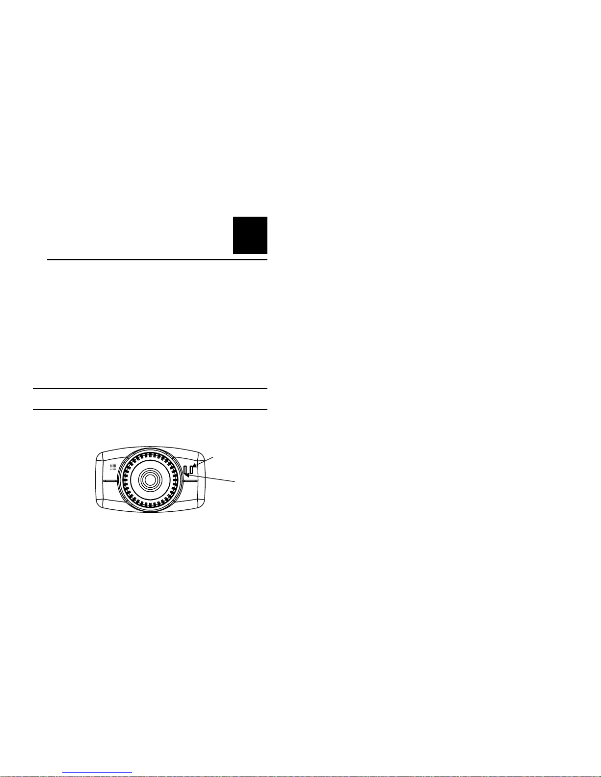
Front Panel
Power LED
Link LED
13
Power LED
The Power LED is positioned on the right side of the Internet
Camera’s lens while facing the Internet Camera.
A steady blue light confirms that the Internet Camera is powered
on.
Link LED
The Link LED is positioned on the right side of the Internet
Camera’s lens while facing the Internet Camera. It is located
right of the Power LED
A steady orange light confirms that the camera has good
connection to LAN connectivity.
Dependent on the data traffic the LED will begin to flash to
indicate that the Internet Camera is receiving/sending data
from/to the network.
14
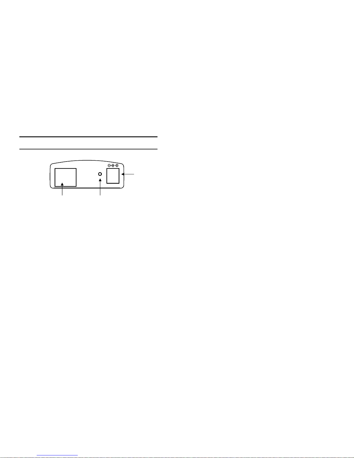
Rear Panel
Network Cable Connector
The Internet Camera’s rear panel features an RJ-45 connector for
connections to 10Base-T Ethernet cabling or 100Base-TX Fast
Ethernet cabling (which should be Category 5 twisted-pair cable).
The port supports the Auto MDI-X type, allowing the Internet
Camera to automatically detect or negotiate the transmission
speed of the network.
DC Power Connector
The DC power input connector is located on the Internet
Camera’s rear panel, and is labeled DC 5V with a single jack
socket to supply power to the Internet Camera. Power will be
generated when the power supply is connected to a wall outlet.
Network Cable
Connector
DC Power
Connector
Reset Button
10/100 Ethernet
DC 5V
Reset
15
Reset Button
Reset will be initiated when the reset button is pressed once, and
Power LED begins to flash.
Factory Reset will be initiated when the reset button is pressed
continuously for three seconds or when Power LED begins to
light up. Release the reset button and the Power LED will begin
to flash, indicating the Internet Camera is changing to factory
reset. The IP address will also return to the default setting as
192.168.0.20.
16
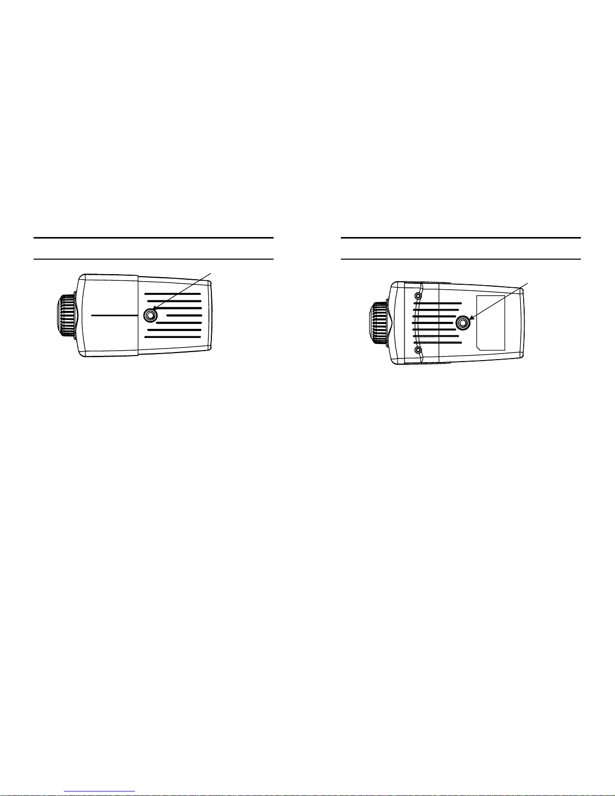
Top Panel
Screw Hole
Located on the top panel of the Internet Camera, the screw hole is
used to connect the camera stand onto the Internet Camera by
attaching the screw head on the camera stand into the screw hole
of the Internet Camera.
Screw Hole
17
Bottom Panel
Screw Hole
Located on the bottom panel of the Internet Camera, the screw
hole is used to connect the camera stand onto the Internet Camera
by attaching the screw head on the camera stand into the screw
hole of the Internet Camera.
Screw Hole

18
5
UNPACKING THE
INTERNET CAMERA
Carefully remove all items from the package. In addition to this
User’s Guide, be certain that you have:
•One Internet Camera
•One Utility CD-ROM
•One Quick Installation Guide
•One Camera Metal Stand
•One RJ-45 Ethernet Cable
•One Power Adapter
If any item is missing, or if you find any damage or mismatch,
promptly contact your dealer for assistance.
19
Connecting the Internet Camera
to the Camera Stand
The Internet Camera comes
with a camera stand (optional) with a
swivel ball screw head that can be attached
to the Internet Camera's bottom
screw hole. Attach the camera stand to
the Internet Camera and station
it for your application. There are three holes
located in the base of the camera stand
allowing the Internet Camera to
be mounted on the ceiling or any wall
securely.
Other manuals for TV-IP100 - DATA SHEETS
5
Table of contents
Other TRENDnet Webcam manuals

TRENDnet
TRENDnet TV-PC100 User manual

TRENDnet
TRENDnet TV-IP672WI User manual

TRENDnet
TRENDnet TV-PC350 User manual

TRENDnet
TRENDnet TV-PC100 User manual

TRENDnet
TRENDnet TV-PC301 User manual

TRENDnet
TRENDnet TV-IP100 - DATA SHEETS User manual

TRENDnet
TRENDnet TV-IP672WI User manual

TRENDnet
TRENDnet TV-IP100 - DATA SHEETS User manual

TRENDnet
TRENDnet TV-PC301 User manual

TRENDnet
TRENDnet TV-IP201W User manual


