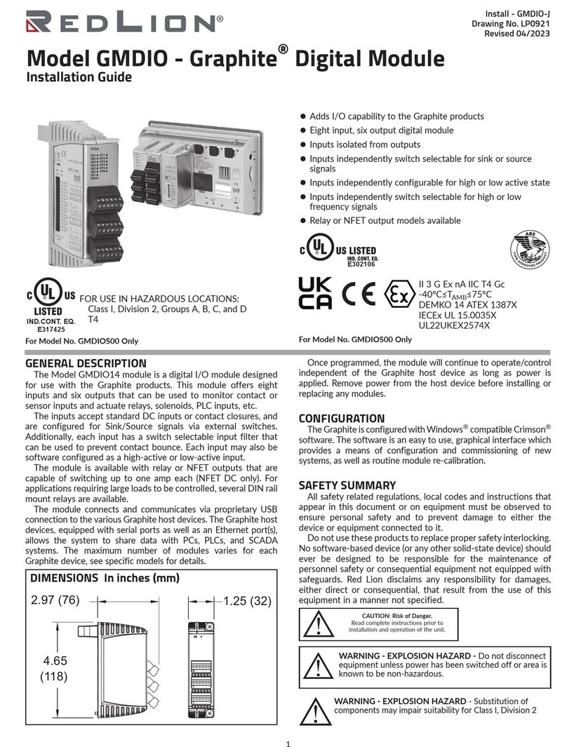
TRIAC TMC-4 User manual

TMC4
Modbus RTU and TCP Modules
Installation & Operation Manual
1
11/10/22
www.atcontrols.com
IOM08147 REVISION 03
Installation and Operation Manual
TMC4 Modbus Module
Single and Dual Channel Modbus RTU, Single Port ModbusTCP
1. Overview
The Triac Modbus modules are a plug-in option module for use with the
TMC4 controller providing communication with the TMC4 control card
through Modbus RTU or ModbusTCP protocol. The TCP module, item
TMC-4C006-002, is available with a single port connection. The RTU
module is available in both a single isolated channel, item TMC-4C005-
001, and dual isolated channel, item TMC-4C005-003. The dual channel
module supports communication via two independent ports under one ID.
This dual channel configuration is useful for operating physically redundant
networks. Wiring, communication parameters, and best practices are all
common between the single and dual channel module operation.
Features
RTU Modules
•Addresses from 1 to 246
•None, Odd or Even parity
•9600, 19.2k, 57.6k, 115.2k baud rates
TCP Module
•IP parameters configurable via TMC4 menus or by terminal
program with on-board USB connection
•Supports up to 8 concurrent connections.
Installation
The TMC4 Modbus module is installed in the TMC4 control board option
module slot using (2) 4-40 x 1/4" screws. Insert card edge in the mini PCI
express connector and rotate module flat to secure with the screws.
Single Channel
TMC-4C005-001
Dual Channel
TMC-4C005-003
ModbusTCP
TMC-4C006-002
Insert option module into
connector and rotate flat. Tighten
with #4-40 x 1/4” fasteners.

TMC4
Modbus RTU and TCP Modules
Installation & Operation Manual
2
11/10/22
www.atcontrols.com
IOM08147 REVISION 03
Wiring
The wiring pinout for the RTU single channel and RTU dual channel module is shown below. The TCP module only
requires RJ45 connection.
RTU Single Channel
TMC-4C005-001
ModbusTCP
TMC-4C006-002
RTU Dual Channel
TMC-4C005-003
COM1 A
COM1 B
COM
RJ45
JACK
COM1 A
COM1 B
SHIELD
COM2 A
COM2 B

TMC4
Modbus RTU and TCP Modules
Installation & Operation Manual
3
11/10/22
www.atcontrols.com
IOM08147 REVISION 03
2. Network
Modbus RTU modules communicate over RS-485 network. For best results using either of the RTU modules, a RS-485
cable with recommended 120Ω characteristic impedance should be used for network wiring. For the dual channel RTU
module, separate RS-485 communication cables must be used for both Network 1 and Network 2 as shown. For single
channel RTU module, only Network 1 cabling is required.
A 120Ω termination resistance at master and last slave node on the network is required for best performance. Maximum
number of nodes per multi-drop network should be limited to 32 nodes. If greater than 32 nodes are required on a
network, repeaters should be utilized.
Polling nodes simultaneously on both ports for a dual channel network should be avoided. A minimum 500ms polling rate
and delay of 20ms between polls of the same device on both channels is recommended.
ModbusTCP module implements the Modbus protocol onto a TCP/IP based communication. TCP module should be wired
using standard Ethernet network components (switch etc.) and IT practices.
RTU Cable Length
The theoretical maximum cable length for RS-485 network is 1.2 km (3900 feet). This also includes the length of any
network stubs used. Maximum cable length decreases as the data rate increases as shown below. Other considerations
may decrease actual maximum cable length, such as characteristic impedance mismatch of cable to master.
120Ω
Termination
120Ω
Termination
Maximum 32 nodes per multi-drop network

TMC4
Modbus RTU and TCP Modules
Installation & Operation Manual
4
11/10/22
www.atcontrols.com
IOM08147 REVISION 03
Network Topology
The Modbus RTU module should be wired in either a daisy chain topology, or a bus/backbone with stubs for best results.
If backbone with stubs topology is used, the length of stubs should be kept as short as possible. Star, ring, or
combinations thereof, should be avoided. ModbusTCP module can be connected using any topology compatible with
Ethernet networks such as star, ring, or combination thereof.
Network Type
RTU Module
TCP Module
Daisy Chain
Yes
No
Bus or Backbone with Stubs
Yes
No
Star
No
Yes
Ring
No
Yes
Backbone with Stars
No
Yes

TMC4
Modbus RTU and TCP Modules
Installation & Operation Manual
5
11/10/22
www.atcontrols.com
IOM08147 REVISION 03
3. Setup
To operate with Modbus commands, the TMC4 controller must first be configured for Modbus RTU or ModbusTCP
communication. Refer to TMC4 IOM for details.
•Set Command Type in the COMMAND CONFIG submenu to Comms.
•Set Position Type in the POSITION CONFIG submenu to either Limit Switch or Potentiometer depending on if
on/off actuation or proportional/modulating actuation.
oIf operating as Potentiometer positioning, program the 0% and 100% positions in the Calibrate Close and
Calibrate Open setting.
•Set Communication Type in the COMMS CONFIG submenu to Modbus RTU or ModbusTCP.
Set communication settings such as unit address, baud rate and parity for RTU modules, and IP address, subnet
mask and gateway for TCP modules in the COMMS CONFIG submenu.
NOTE: Cycle power to the TMC4 after communication settings are changed to ensure connection.
4. Operation
Limit Switch Positioning Operation
When operating with limit switches for on/off or two position control, the TMC4 Position Type setting in the POSITION
CONFIG submenu should be set to Limit Switch. When operating in this mode, Bit 1 and Bit 2 in Register 40009 control the
actuator direction and movement. The actuator can also be controlled by writing specific values to Register 40010.
Bits 1 –4 in Register 40001, provide the feedback information about the travel direction and end of travel position of the
actuator. Operating details are provided below.
OPERATION
Register 40009, Action Bits/Flags 2
Bit 2
Bit 1
Description
0
x
De-energize motor outputs
and stop actuator.
1
0
Energize motor outputs and
drive actuator CW.
1
1
Energize motor outputs and
drive actuator CCW.
FEEDBACK
Register 40001, Status Flags 1
Position
Movement
Description
Bit 4
Bit 3
Bit 2
Bit 1
Position
Movement
0
0
0
0
Between limits
Stopped
0
0
0
1
Between limits
CCW
0
0
1
0
Between limits
CW
0
0
1
1
?
?
0
1
0
0
CCW limit
Stopped
0
1
0
1
?
?
0
1
1
0
CCW limit
CW
(1)
0
1
1
1
?
?
1
0
0
0
CW limit
Stopped
1
0
0
1
CW limit
CCW
(1)
(1) This state will be present immediately when reversing direction until the position
cam disengages the position limit switch. If this state persists, it may indicate jam or
obstruction condition.
OPERATION
Register 40010, Command Position
Value
Description
0
Energize motor outputs and
drive actuator CW.
500
De-energize motor outputs
and stop actuator.
1000
Energize motor outputs and
drive actuator CCW.
Note that even though the motor stops when the destination travel limit switch is closed, the motor outputs of the control
board remain energized until a stop command is written to Register 40009 or 40010.
In Register 40009, Bit 1 establishes the direction of actuator travel and Bit 2 energizes or de-energizes the motor output
corresponding to the direction determined by Bit 1.
If Bit 1 = 0, the actuator is set to move in the CW direction. If Bit 1 = 1, the actuator is set to move in the CCW direction.

TMC4
Modbus RTU and TCP Modules
Installation & Operation Manual
6
11/10/22
www.atcontrols.com
IOM08147 REVISION 03
If Bit 2 = 0, the motor output is not energized. If Bit 2 = 1, the CW motor output is energized when Bit 1 = 0 and the CCW
motor output is energized when Bit 1 = 1. Unless Bit 2 is cleared, the actuator will continue to move in the specified direction
until the corresponding end of travel limit switch closes.
It is acceptable to change direction with Bit 1 while maintaining Bit 2 = 1. If the direction is changed while the actuator is
moving, a short delay occurs before the actuator begins moving in the opposite direction.
Writing values into Register 40010 will automatically set Bit 1 and Bit 2 in Register 40009 according to the action specified.
CAUTION! When writing to Bit 1 and Bit 2 of Register 40009, be careful not to change the other register bits.
In Register 40001, Bit 1 and Bit 2 indicate the direction of travel. Bit 3 and Bit 4 indicate if the actuator is at the full CCW or
full CW limit respectively.
While the actuator is moving in the CW direction, Bit 2 = 1. When the actuator reaches the CW end of travel limit switch, Bit
2 = 0 and Bit 4 = 1. The CW motor output is de-energized.
While the actuator is moving in the CCW direction, Bit 1 = 1. When the actuator reaches the CCW end of travel limit
switch, Bit 1 = 0 and Bit 3 = 1. The CCW motor output is de-energized.
Potentiometer Positioning Operation
When operating with feedback potentiometer for proportional or modulating control, the TMC4 Position Type setting in the
POSITION CONFIG submenu should be set to Potentiometer. In this mode, the actuator is controlled using the Command
Position Register 40010, and the Sensitivity/Deadband Register 40013. Note, the deadband can also set by the on-board
menus. The actual location of the actuator is indicated by the Current Position Register 40008.
When a new command position value is written to Register 40010, the new value is compared to the current position value
in Register 40008. If the difference between the twovalues is greater than the sensitivity/deadband value in Register 40010,
the actuator begins moving towards the new command position. When the current position value is within the limits of the
command position and sensitivity/deadband value in Register 40010, the actuator is stopped.
Bit 1 and Bit2 in Register 40001 are also usedto indicate the direction of travel. If the actuator ismoving in the CW direction,
Bit 2 = 1. If the actuator is moving in the CCW direction, Bit 1 = 1. When the actuator reaches the command position value
and is stopped, Bit 1 and Bit 2 will equal 0.
Obstruction or Jam Detection
When a move command is given by either setting Bit 1 and Bit 2 in Register 40009, or by writing valid value to Register
40010, a timer is immediately started. The timer continues to increment once every second. After each increment, the timer
value is compared to the value set in Register 40011 for the Travel Timeout.
If the destination travel limit switch closes, or the position setpoint is reached before the timer value is greaterthan the value
in Register 40011, the actuator is operating normally.
If the destination travel limit switch IS NOT closed, or the position setpoint is not reached before the timer value is greater
than the value in Register 40011, a jam or obstruction has prevented the valve from operating properly. The active motor
output is de-energized, and Bit 5 in Register 40001 is set.

TMC4
Modbus RTU and TCP Modules
Installation & Operation Manual
7
11/10/22
www.atcontrols.com
IOM08147 REVISION 03
5. Modbus
Function Codes
The TMC4 Modbus RTU and TCP modules are a Modbus slave that supports the following Modbus functions.
Code
Code
(hex)
Code Definition
03
0x03
Read Holding Registers
16
0x10
Write Multiple Registers
Function 03 reads the contents of a contiguous block of holding registers. All registers, 40001-40017 are readable with this
function.
Function 16 writes values into a sequence of adjacent holding registers. Only registers, 40009-40017 can be written to with
this function.
Registers
All registers are 16 bits in length. When the register is addressed in the data communications, the register is assigned a
hexadecimal value starting with 0x00. Therefore, registers numbered 40001-40017 are addressed as 0-16 in decimal, or
0x00 to 0x10 in hexadecimal resulting in the register always addressed one value below the specified decimal register
number.
Register
No.
Register
Address
Address Name
16 bit / Digital Name
Unit
Scale
Range
Default
Read / Write
40001
0x00
STATUS FLAGS 1
INT
bit 1
CCW Movement
Bit
N/A
True/False
N/A
Read
bit 2
CW Movement
Bit
N/A
True/False
N/A
Read
bit 3
CCW Travel Limit
Bit
N/A
True/False
N/A
Read
bit 4
CW Travel Limit
Bit
N/A
True/False
N/A
Read
bit 5
Actuator Obstructed
Bit
N/A
True/False
N/A
Read
bit 6
-
-
-
-
-
-
bit 7
Control Mode
Bit
N/A
True/False
N/A
Read
bit 8
Operating Mode
Bit
N/A
True/False
N/A
Read
bit 9-16
-
-
-
-
-
-
40002
0x01
TOTAL POWER
ON TIME HI /
FIRMWARE
VERSION
INT
bit 1-8
Total Power On Time
(Upper Byte)
Hour
1
65,536 –16,711,680
(0 –16,777,215 when used with
Register 40003)
0
Read
bit 9-16
Firmware Version
Int.
1
0-255
N/A
Read
40003
0x02
TOTAL POWER
ON TIME LO
INT
Hour
1
0 –65,535
(0 –16,777,215 when used with
Register 40002 bits 1-8)
0
Read

TMC4
Modbus RTU and TCP Modules
Installation & Operation Manual
8
11/10/22
www.atcontrols.com
IOM08147 REVISION 03
40004
0x03
TOTAL MOTOR
RUN TIME HI
INT
bit 1-8
Total Motor Run Time
(Upper Byte)
Count
1
65,536 –16,711,680
(0 –16,777,215 when used with
Register 40005)
0
Read
bit 9-16
-
-
-
-
-
-
40005
0x04
TOTAL MOTOR
RUN TIME LO
INT
Count
1
0 –65,535
(0 –16,777,215 when used with
Register 40004 bits 1-8)
0
Read
40006
0x05
TOTAL MOTOR
STARTS HI
INT
bit 1-8
Total Motor Starts
(Upper Byte)
Count
1
65,536 –16,711,680
(0 –16,777,215 when used
with Register 40007)
0
Read
bit 9-16
-
-
-
-
-
-
40007
0x06
TOTAL MOTOR
STARTS LO
INT
Count
1
0 –65,535
(0 –16,777,215 when used
with Register 40006 bits 1-8)
0
Read
40008
0x07
CURRENT
POSITION
INT
%
0.1
0-1000
N/A
Read
40009
0x08
ACTION BITS /
STATUS FLAGS 2
INT
bit 1
Direction
Bit
N/A
True/False
N/A
Read / Write
bit 2
Motor Output
Bit
N/A
True/False
N/A
Read / Write
bit 3
Reset Actuator
Bit
N/A
True/False
N/A
Read / Write
bit 4
-
-
-
-
-
-
bit 5
-
-
-
-
-
-
bit 6
-
-
-
-
-
-
bit 7
Fault Action
Bit
N/A
0,0 –In Place
0,1 –CCW
1,0 –CS
1,1 –To Position (40017)
0,0
Read / Write
bit 8
bit 9
Power Interrupt Flag
Bit
N/A
True/False
N/A
Read / Write
bit 10
Reset Flag
Bit
N/A
True/False
N/A
Read / Write
bit 11
-
-
-
-
-
-
bit 12
Save To EEPROM
Bit
N/A
True/False
N/A
Read / Write
bit 13
Fault Flag
Bit
N/A
True/False
N/A
Read / Write
bit 14
-
-
-
-
-
-
bit 15
-
-
-
-
-
-
bit 16
-
-
-
-
-
-
40010
0x09
COMMAND
POSITION
INT
%
0.1
0 –1000 (Modulating)
0, 500, 1000 (Limit Switch)
N/A
Read / Write
40011
0x0A
TRAVEL TIMEOUT
INT
sec
1
5 - 255
60
Read / Write
40012
0x0B
RESERVE
-
-
-
-
-
-
40013
0x0C
SENSITIVITY
INT
%
0.1
1 - 25
5
Read / Write
40014
0x0D
COMMUNICATION
TIMEOUT
INT
sec
0.01
100 - 10,000
1000
Read / Write
40015
0x0E
RESERVE
-
-
-
-
-
-
40016
0x0F
RESERVE
-
-
-
-
-
-
40017
0x10
FAULT POSITION
INT
%
0.1
0 - 1000
N/A
Read / Write

TMC4
Modbus RTU and TCP Modules
Installation & Operation Manual
9
11/10/22
www.atcontrols.com
IOM08147 REVISION 03
Status Flags 1 Register
Register Number
40001
Unit
Scale
Range
Default
Register Address
0x00
n/a
n/a
n/a
n/a
Read/Write
R
40001
Byte 2 (MSB)
Byte 1 (LSB)
B16
B15
B14
B13
B12
B11
B10
B9
B8
B7
B6
B5
B4
B3
B2
B1
The Status Flags 1 register provides flags to indicate various status and operating conditions. The register bits are assigned
the functionality provided below.
Bit
Description
Bit 1
CCW Movement bit indicates if the CCW motor output terminal is energized and is used to indicate CCW movement.
Bit 2
CW Movement bit indicates if the CW motor output terminal is energized and is used to indicate CW movement.
Bit 3
CCW Travel Limit bit indicates if the open travel limit switch is closed.
Bit 4
CW Travel Limit bit indicates if the close travel limit switch is closed.
Bit 5
Actuator Obstruction bit indicates if the time set in the Travel Timeout register 40011 has been exceeded before the
actuator reaches its appropriate end of travel position.
Bit 6
Not used
Bit 7
Positioning Mode bit indicates if the Position Type in the menus is set to Limit Switch or Potentiometer. Limit Switch is
for two position control using limit switches for position feedback. Potentiometer is used for proportional or modulating
control using a potentiometer for position feedback.
Bit 8
OperatingMode bit indicates if the controller is in Run mode or Configuration mode. The controller is considered to be in
configuration mode when entering into any of the configuration submenus.
Bit 9-16
Not used
Byte 1 (LSB)
Bit 8
Bit 7
Bit 6
Bit 5
Bit 4
Bit 3
Bit 2
Bit 1
Operating
Mode
Positioning
Mode
-
Obstruction
CW
Limit
CCW
Limit
CW
Move
CCW
Move
0: Motor CCW output not on
1: Motor CCW output on
0: Motor CW output not on
1: Motor CW output on
0: CCW limit switch not closed
1: CCW limit switch closed
0: CW limit switch not closed
1: CW limit switch closed
0: No obstruction detected
1: Obstruction detected
0: n/a
1: n/a
0: Position Type = Limit Switch
1: Position Type = Potentiometer
0: Run mode
1: Configuration mode
Byte 2 (MSB)
Bit 16
Bit 15
Bit 14
Bit 13
Bit 12
Bit 11
Bit 10
Bit 9
-
-
-
-
-
-
-
-
n/a
n/a
n/a
n/a
n/a
n/a
n/a
n/a

TMC4
Modbus RTU and TCP Modules
Installation & Operation Manual
10
11/10/22
www.atcontrols.com
IOM08147 REVISION 03
Total Power On Time / Firmware
Register Number
40002 / 40003
Unit
Scale
Range
Default
Register Address
0x01 / 0x02
Hour
1
0 –16,777,216
0x00000000 –0x00FFFFFF
n/a
Read/Write
R
Version
1
0 –255
0x00 –0xFF
n/a
40002
40003
Byte 2 (MSB)
Byte 1 (LSB)
Byte 2 (MSB)
Byte 1 (LSB)
B16
B15
B14
B13
B12
B11
B10
B9
B8
B7
B6
B5
B4
B3
B2
B1
B16
B15
B14
B13
B12
B11
B10
B9
B8
B7
B6
B5
B4
B3
B2
B1
Firmware Version
Total Powered On Time
0 –255
0 –16,777,216 (hours)
The Total Power on Time/Firmware registers store the total time (in hours) the board has been powered on as well as the
current version of the firmware. The firmware version is stored in the upper 8 bits of Register 40002. The lower 8 bits of
Register 40002 and all 16 bits of Register 40003 contain the 24-bit value representing the time the board has been powered
on, providing for between 0 and 16,777,216 hours. This value resets when board power is removed.
When reading the registers, the 8 bits in Register 40002 represent the most significant bits of the time, while all 16 bits in
Register 40003 represent the least significant bits of the time. It is recommended to read both registers with the same
command. In order to extract the length of time the board has been powered on, the upper 8 bits of Register 40002 must
be masked off. In order to extract the firmware version, the lower 8 bits of Register 40002 must be masked off.
Total Motor Run Time
Register Number
40004 / 40005
Unit
Scale
Range
Default
Register Address
0x03 / 0x04
Hour
1
0 –16,777,216
0x00000000 –0x00FFFFFF
n/a
Read/Write
R
40004
40005
Byte 2 (MSB)
Byte 1 (LSB)
Byte 2 (MSB)
Byte 1 (LSB)
B16
B15
B14
B13
B12
B11
B10
B9
B8
B7
B6
B5
B4
B3
B2
B1
B16
B15
B14
B13
B12
B11
B10
B9
B8
B7
B6
B5
B4
B3
B2
B1
-
0 –16,777,216 (hours)
The Total Motor Run Time registers store the total combined time (in hours) the CW and CCW motor outputs of the board
have been energized. The lower 8 bits of Register40004 and all 16 bits of Register 40005 contain the 24-bit value, providing
for between 0 and 16,777,216 hours. This value resets when board power is removed.
When reading the registers, the 8 bits in Register 40004 represent the most significant bits of the time, while all 16 bits in
Register 40005 represent the least significant bits of the time. It is recommended to read both registers with the same
command.

TMC4
Modbus RTU and TCP Modules
Installation & Operation Manual
11
11/10/22
www.atcontrols.com
IOM08147 REVISION 03
Total Motor Starts
Register Number
40006 / 40007
Unit
Scale
Range
Default
Register Address
0x05 / 0x06
Count
1
0 –16,777,216
0x00000000 –0x00FFFFFF
n/a
Read/Write
R
40004
40005
Byte 2 (MSB)
Byte 1 (LSB)
Byte 2 (MSB)
Byte 1 (LSB)
B16
B15
B14
B13
B12
B11
B10
B9
B8
B7
B6
B5
B4
B3
B2
B1
B16
B15
B14
B13
B12
B11
B10
B9
B8
B7
B6
B5
B4
B3
B2
B1
-
0 –16,777,216 (count)
The Total Motor Starts registers store the total count fornumber of times the CW and CCW motor outputs of the board have
been energized. The lower 8 bits of Register 40006 and all 16 bits of Register 40007 contain the 24-bit value, providing for
between 0 and 16,777,216 total number of starts. This value resets when board power is removed.
When reading the registers, the 8 bits in Register 40006 represent the most significant bits of the count, while all 16 bits in
Register 40007 represent the least significant bits of the count. It is recommended to read both registers with the same
command.
Current Position
Register Number
40008
Unit
Scale
Range
Default
Register Address
0x07
%
0.1
0 –1000
0x0000 –0x03E8
n/a
Read/Write
R
40008
Byte 2 (MSB)
Byte 1 (LSB)
B16
B15
B14
B13
B12
B11
B10
B9
B8
B7
B6
B5
B4
B3
B2
B1
0 –1000
0.0% to 100.0%
The Current Position register is used to track the current actuator position in potentiometer positioning using a feedback
potentiometer. The range is automatically scaled based on the calibrated 0% and 100% positions.
The values inthe register span from0 to 1000, which corresponds to 0.0% and100.0% respectively. With0.0% representing
a fully closed actuator, and 100.0% representing a fully open actuator, a value of 674 represents the actuators is 67.4%
open.

TMC4
Modbus RTU and TCP Modules
Installation & Operation Manual
12
11/10/22
www.atcontrols.com
IOM08147 REVISION 03
Action Bits/Flags 2 Register
Register Number
40009
Unit
Scale
Range
Default
Register Address
0x08
n/a
n/a
n/a
n/a
Read/Write
R / W
40009
Byte 2 (MSB)
Byte 1 (LSB)
B16
B15
B14
B13
B12
B11
B10
B9
B8
B7
B6
B5
B4
B3
B2
B1
The Action Bits/Flags 2 register provides individual bits for multiple operation settings as well as resettable flags used to
indicate various status changes.
Bit
Description
Bit 1
Direction bit sets the direction to move the actuator when using limit switch positioning. Use this bit with Bit 2 to move
the actuator in on/off applications. The status of this bit determines which motor output is energized when Bit 2 is set.
Bit 2
Output Status bit energizes the motor output determined by Bit 1. Set the desired travel direction with Bit 1 and either
turn on or off the motor output with this bit.
Bit 3
Reset bit resets registers 40001 (bits 1-6), 40009 (bits 1-4), 40010.
Bit 4-6
Not used
Bit 7 & 8
Fault Action bits determine the movement when the time between communication exceeds the Communication Timeout
value in Register 40014. This can also be configured in the on-board menus.
Bit 9-16
Not used
Byte 1 (LSB)
Bit 8
Bit 7
Bit 6
Bit 5
Bit 4
Bit 3
Bit 2
Bit 1
Fault Action
-
-
-
Reset
Motor Out
Status
Direction
0: Move CW
1: Move CCW
0: Motor output not energized
1: Motor output energized
0: No effect
1: Register reset sent
0: n/a
1: n/a
0: n/a
1: n/a
0: n/a
1: n/a
(0,0): Fail in place (default)
(0,1): Fail full CCW
(1,0): Fail full CW
(1,1): Fail to position (potentiometer positioning)
Byte 2 (MSB)
Bit 16
Bit 15
Bit 14
Bit 13
Bit 12
Bit 11
Bit 10
Bit 9
-
-
-
-
-
-
-
-
n/a
n/a
n/a
n/a
n/a
n/a
n/a
n/a

TMC4
Modbus RTU and TCP Modules
Installation & Operation Manual
13
11/10/22
www.atcontrols.com
IOM08147 REVISION 03
Command Position
Register Number
40010
Unit
Scale
Range
Default
Register Address
0x09
%
0.1
0 –1000
0x0000 –0x03E8
(32,768 –33,768)
(0x8000 –0x83E8)
n/a
Read/Write
R / W
40010
Byte 2 (MSB)
Byte 1 (LSB)
B16
B15
B14
B13
B12
B11
B10
B9
B8
B7
B6
B5
B4
B3
B2
B1
0 –1000
0.0% to 100.0%
If a value outside of the acceptable range of 0 to 1000 is written, the actuator will not move. When control board has power
applied, or is reset using Bit 3 in Register 40009, Bit 16 is set to 1 resulting in a value of 32,768 added to the value currently
in the register. Setting Bit 16 forces the Command Position register value outside of the acceptable 0 to 1000 range and
therefore prevents the actuator from moving. The actuator can be controlled again by writing another value between 0 and
1000.
The Command Position register is used to initiate an actuator move. When the board is configured for potentiometer
positioning, the values span from 0 to 1000, corresponding to 0.0% and 100.0% respectively. Therefore, with 0.0%
representing a fully closed actuator, and 100.0% representing a fully open actuator, a written value of 674 indicates a
command to move the actuator to 67.4% open.
When the board is set to limit switch positioning, a 0 will move the actuator CW, a 500 will stop the actuator, and 1000 will
move the actuator CCW.
Value
Description
Register 40009 bit equivalent
0
Energize motor outputs and drive actuator CW.
Bit 1 = 0, Bit 2 = 1
500
De-energize motor outputs and stop actuator.
Bit 1 = x, Bit 2 = 0
1000
Energize motor outputs and drive actuator CCW.
Bit 1 = 1, Bit 2 = 1
Travel Timeout
Register Number
40011
Unit
Scale
Range
Default
Register Address
0x0A
Second
1
5 –255
0x0005 –0x00FF
60
Read/Write
R / W
40011
Byte 2 (MSB)
Byte 1 (LSB)
B16
B15
B14
B13
B12
B11
B10
B9
B8
B7
B6
B5
B4
B3
B2
B1
5 –255
5 Seconds to 255 Seconds
The Travel Timeout register is to determine a stall or obstruction condition identified by Bit 5 in Register 40001. The value
stored in this register represents the maximum time allowed between energizing a motor output and reaching the command
position or limit before identifying an obstruction. This value should typically be set greater than the normal travel time of
the actuator from full open to full close.
Values in this register can be between 5 and 255 with each integer representing 1 second. The default value is set to 60
representing a time of 60 seconds.

TMC4
Modbus RTU and TCP Modules
Installation & Operation Manual
14
11/10/22
www.atcontrols.com
IOM08147 REVISION 03
Reserved
Register Number
40012
Unit
Scale
Range
Default
Register Address
0x0B
n/a
n/a
n/a
n/a
Read/Write
R / W
This register is currently not used.
Sensitivity/Deadband
Register Number
40013
Unit
Scale
Range
Default
Register Address
0x0C
%
0.1
1 –25
0x0001 –0x0019
5
Read/Write
R / W
40013
Byte 2 (MSB)
Byte 1 (LSB)
B16
B15
B14
B13
B12
B11
B10
B9
B8
B7
B6
B5
B4
B3
B2
B1
1 –25
1.0% to 2.5%
The Sensitivity/Deadband register storesthe necessarychange between the value written toRegister 40010 and the current
value in Register 40008 before an actuator movement is initiated. It also represents the range outside of the setpoint the
actuator will stop.
Values in this register can be between 1 and 25 with each integer representing 0.1%. The default value is set to 5
representing 0.5%. Using the default value of 0.5%, if the actuator position is at 50.0%, indicated by a value of 500 in
Register 40008, the value written to Register 40010 must be greater than 505 or less than 495.
Communication Timeout
Register Number
40014
Unit
Scale
Range
Default
Register Address
0x0D
Second
0.01
100 –10,000
0x0064 –0x2710
1000
Read/Write
R / W
40014
Byte 2 (MSB)
Byte 1 (LSB)
B16
B15
B14
B13
B12
B11
B10
B9
B8
B7
B6
B5
B4
B3
B2
B1
100 –10,000
0.1 Seconds to 100 Seconds
The Communication Timeout register stores the maximum time allowed with no communication received from the master
device before entering a fault condition. When this time is exceeded, the actuator will move to the position set by Bit 7 and
Bit 8 in Register 40009.The master should communicate with each actuator on the bus within the time set in this register.
Doing so will ensure the actuator moves to the fault position determined by Bit 7 and Bit 8 in Register 40009 only when an
unintended lapse in communication is encountered.
Values in this register can be between 100 and 10,000 with each integer representing 0.01 seconds. The default value is
set to 1000 representing 10 seconds.

TMC4
Modbus RTU and TCP Modules
Installation & Operation Manual
15
11/10/22
www.atcontrols.com
IOM08147 REVISION 03
Reserved
Register Number
40015
Unit
Scale
Range
Default
Register Address
0x0E
n/a
n/a
n/a
n/a
Read/Write
R / W
This register is currently not used.
Reserved
Register Number
40016
Unit
Scale
Range
Default
Register Address
0x0F
n/a
n/a
n/a
n/a
Read/Write
R / W
This register is currently not used.
Fault Position
Register Number
40017
Unit
Scale
Range
Default
Register Address
0x10
%
0.01
0 –1000
0x0000 –0x03E8
n/a
Read/Write
R / W
40017
Byte 2 (MSB)
Byte 1 (LSB)
B16
B15
B14
B13
B12
B11
B10
B9
B8
B7
B6
B5
B4
B3
B2
B1
0 –1000
0.0% to 100.0%
The Fault Position register is used in potentiometer positioning to set a position to move the actuator for a fault condition.
The values inthe register span from0 to 1000, which corresponds to 0.0% and100.0% respectively. With0.0% representing
a fully closed actuator, and 100.0% representing a fully open actuator, a value of 674 represents the actuator will fail to the
67.4% open position either from fault condition.
Failing to the position specified in this register when a fault condition occurs is achieved by setting both Bit 7 and Bit 8 in
Register 40009 high.

TMC4
Modbus RTU and TCP Modules
Installation & Operation Manual
16
11/10/22
www.atcontrols.com
IOM08147 REVISION 03
Appendix A
Number System Conversion
DEC
OCT
HEX
BIN
DEC
OCT
HEX
BIN
DEC
OCT
HEX
BIN
DEC
OCT
HEX
BIN
0
000
00
0000 0000
16
020
10
0001 0000
32
040
20
0010 0000
48
060
30
0011 0000
1
001
01
0000 0001
17
021
11
0001 0001
33
041
21
0010 0001
49
061
31
0011 0001
2
002
02
0000 0010
18
022
12
0001 0010
34
042
22
0010 0010
50
062
32
0011 0010
3
003
03
0000 0011
19
023
13
0001 0011
35
043
23
0010 0011
51
063
33
0011 0011
4
004
04
0000 0100
20
024
14
0001 0100
36
044
24
0010 0100
52
064
34
0011 0100
5
005
05
0000 0101
21
025
15
0001 0101
37
045
25
0010 0101
53
065
35
0011 0101
6
006
06
0000 0110
22
026
16
0001 0110
38
046
26
0010 0110
54
066
36
0011 0110
7
007
07
0000 0111
23
027
17
0001 0111
39
047
27
0010 0111
55
067
37
0011 0111
8
010
08
0000 1000
24
030
18
0001 1000
40
050
28
0010 1000
56
070
38
0011 1000
9
011
09
0000 1001
25
031
19
0001 1001
41
051
29
0010 1001
57
071
39
0011 1001
10
012
0A
0000 1010
26
032
1A
0001 1010
42
052
2A
0010 1010
58
072
3A
0011 1010
11
013
0B
0000 1011
27
033
1B
0001 1011
43
053
2B
0010 1011
59
073
3B
0011 1011
12
014
0C
0000 1100
28
034
1C
0001 1100
44
054
2C
0010 1100
60
074
3C
0011 1100
13
015
0D
0000 1101
29
035
1D
0001 1101
45
055
2D
0010 1101
61
075
3D
0011 1101
14
016
0E
0000 1110
30
036
1E
0001 1110
46
056
2E
0010 1110
62
076
3E
0011 1110
15
017
0F
0000 1111
31
037
1F
0001 1111
47
057
2F
0010 1111
63
077
3F
0011 1111
64
100
40
0100 0000
80
120
50
0101 0000
96
140
60
0110 0000
112
160
70
0111 0000
65
101
41
0100 0001
81
121
51
0101 0001
97
141
61
0110 0001
113
161
71
0111 0001
66
102
42
0100 0010
82
122
52
0101 0010
98
142
62
0110 0010
114
162
72
0111 0010
67
103
43
0100 0011
83
123
53
0101 0011
99
143
63
0110 0011
115
163
73
0111 0011
68
104
44
0100 0100
84
124
54
0101 0100
100
144
64
0110 0100
116
164
74
0111 0100
69
105
45
0100 0101
85
125
55
0101 0101
101
145
65
0110 0101
117
165
75
0111 0101
70
106
46
0100 0110
86
126
56
0101 0110
102
146
66
0110 0110
118
166
76
0111 0110
71
107
47
0100 0111
87
127
57
0101 0111
103
147
67
0110 0111
119
167
77
0111 0111
72
110
48
0100 1000
88
130
58
0101 1000
104
150
68
0110 1000
120
170
78
0111 1000
73
111
49
0100 1001
89
131
59
0101 1001
105
151
69
0110 1001
121
171
79
0111 1001
74
112
4A
0100 1010
90
132
5A
0101 1010
106
152
6A
0110 1010
122
172
7A
0111 1010
75
113
4B
0100 1011
91
133
5B
0101 1011
107
153
6B
0110 1011
123
173
7B
0111 1011
76
114
4C
0100 1100
92
134
5C
0101 1100
108
154
6C
0110 1100
124
174
7C
0111 1100
77
115
4D
0100 1101
93
135
5D
0101 1101
109
155
6D
0110 1101
125
175
7D
0111 1101
78
116
4E
0100 1110
94
136
5E
0101 1110
110
156
6E
0110 1110
126
176
7E
0111 1110
79
117
4F
0100 1111
95
137
5F
0101 1111
111
157
6F
0110 1111
127
177
7F
0111 1111

TMC4
Modbus RTU and TCP Modules
Installation & Operation Manual
17
11/10/22
www.atcontrols.com
IOM08147 REVISION 03
DEC
OCT
HEX
BIN
DEC
OCT
HEX
BIN
DEC
OCT
HEX
BIN
DEC
OCT
HEX
BIN
128
200
80
1000 0000
144
220
90
1001 0000
160
240
A0
1010 0000
176
260
B0
1011 0000
129
201
81
1000 0001
145
221
91
1001 0001
161
241
A1
1010 0001
177
261
B1
1011 0001
130
202
82
1000 0010
146
222
92
1001 0010
162
242
A2
1010 0010
178
262
B2
1011 0010
131
203
83
1000 0011
147
223
93
1001 0011
163
243
A3
1010 0011
179
263
B3
1011 0011
132
204
84
1000 0100
148
224
94
1001 0100
164
244
A4
1010 0100
180
264
B4
1011 0100
133
205
85
1000 0101
149
225
95
1001 0101
165
245
A5
1010 0101
181
265
B5
1011 0101
134
206
86
1000 0110
150
226
96
1001 0110
166
246
A6
1010 0110
182
266
B6
1011 0110
135
207
87
1000 0111
151
227
97
1001 0111
167
247
A7
1010 0111
183
267
B7
1011 0111
136
210
88
1000 1000
152
230
98
1001 1000
168
250
A8
1010 1000
184
270
B8
1011 1000
137
211
89
1000 1001
153
231
99
1001 1001
169
251
A9
1010 1001
185
271
B9
1011 1001
138
212
8A
1000 1010
154
232
9A
1001 1010
170
252
AA
1010 1010
186
272
BA
1011 1010
139
213
8B
1000 1011
155
233
9B
1001 1011
171
253
AB
1010 1011
187
273
BB
1011 1011
140
214
8C
1000 1100
156
234
9C
1001 1100
172
254
AC
1010 1100
188
274
BC
1011 1100
141
215
8D
1000 1101
157
235
9D
1001 1101
173
255
AD
1010 1101
189
275
BD
1011 1101
142
216
8E
1000 1110
158
236
9E
1001 1110
174
256
AE
1010 1110
190
276
BE
1011 1110
143
217
8F
1000 1111
159
237
9F
1001 1111
175
257
AF
1010 1111
191
277
BF
1011 1111
192
300
C0
1100 0000
208
320
D0
1101 0000
224
340
E0
1110 0000
240
360
F0
1111 0000
193
301
C1
1100 0001
209
321
D1
1101 0001
225
341
E1
1110 0001
241
361
F1
1111 0001
194
302
C2
1100 0010
210
322
D2
1101 0010
226
342
E2
1110 0010
242
362
F2
1111 0010
195
303
C3
1100 0011
211
323
D3
1101 0011
227
343
E3
1110 0011
243
363
F3
1111 0011
196
304
C4
1100 0100
212
324
D4
1101 0100
228
344
E4
1110 0100
244
364
F4
1111 0100
197
305
C5
1100 0101
213
325
D5
1101 0101
229
345
E5
1110 0101
245
365
F5
1111 0101
198
306
C6
1100 0110
214
326
D6
1101 0110
230
346
E6
1110 0110
246
366
F6
1111 0110
199
307
C7
1100 0111
215
327
D7
1101 0111
231
347
E7
1110 0111
247
367
F7
1111 0111
200
310
C8
1100 1000
216
330
D8
1101 1000
232
350
E8
1110 1000
248
370
F8
1111 1000
201
311
C9
1100 1001
217
331
D9
1101 1001
233
351
E9
1110 1001
249
371
F9
1111 1001
202
312
CA
1100 1010
218
332
DA
1101 1010
234
352
EA
1110 1010
250
372
FA
1111 1010
203
313
CB
1100 1011
219
333
DB
1101 1011
235
353
EB
1110 1011
251
373
FB
1111 1011
204
314
CC
1100 1100
220
334
DC
1101 1100
236
354
EC
1110 1100
252
374
FC
1111 1100
205
315
CD
1100 1101
221
335
DD
1101 1101
237
355
ED
1110 1101
253
375
FD
1111 1101
206
316
CE
1100 1110
222
336
DE
1101 1110
238
356
EE
1110 1110
254
376
FE
1111 1110
207
317
CF
1100 1111
223
337
DF
1101 1111
239
357
EF
1110 1111
255
377
FF
1111 1111

TMC4
Modbus RTU and TCP Modules
Installation & Operation Manual
18
11/10/22
www.atcontrols.com
IOM08147 REVISION 03
Appendix B
ModbusTCP Configuration via Terminal Program
The IP settings for the TMC4 with ModbusTCP module can be configured using the standard on-board menus. However,
the TMC4 can also be configured using a computer terminal interface program through the USB connection. Note the
ModbusTCP is only compatible with firmware versions 2.03 and later.
1. Install ModbusTCP module in the TMC4 module slot.
2. Power on the TMC4.
3. Set the command type to “Comms” and ensure the communication type is set for ModbusTCP.
4. Configure the IP settings to match the user network via USB to the TMC4 micro USB connection.
a. Connect USB to micro USB cable between TMC4 and PC.
b. Once new serial port is assigned to the TMC4, open a terminal program (TeraTerm, Putty, etc.) under
the newly assigned comm port with parameters: 115200-8-N-1
c. In the terminal, type “help” to see the available commands

TMC4
Modbus RTU and TCP Modules
Installation & Operation Manual
19
11/10/22
www.atcontrols.com
IOM08147 REVISION 03
5. To read the current IP settings, type “ipget”
6. To set IP address, type “ipset 192 168 0 101” to set IP address to 192.168.0.101
7. To set subnet mask, type “subset 255 255 255 0” to set mask to 255.255.255.0
8. To set gateway IP, type “gwset 192 168 0 1” to set gateway to 192.168.0.1
9. The TMC4 confirms the change is successful after each command.
10. Cycle power to the TMC4 to complete configuration of the new network settings.
11. TMC4 is now ready for ModbusTCP communications. Use a ModbusTCP master with the IP set as per above and
use TCP port 502.

TMC4
Modbus RTU and TCP Modules
Installation & Operation Manual
20
11/10/22
www.atcontrols.com
IOM08147 REVISION 03
A-T Controls product, when properly selected, is designed to perform its intended function safely during its useful life. However, the purchaser or user of
A-T Controls products should be aware that A-T Controls products might be used in numerous applications under a wide variety of industrial service
conditions. Although A-T Controls can provide general guidelines, it cannot provide specific data and warnings for all possible applications. The purchaser
/ user must therefore assume the ultimate responsibility for the proper sizing and selection, installation, operation, and maintenance of A-T Controls
products. The user should read and understand the installation operation maintenance (IOM) instructions included with the product and train its employees
and contractors in the safe use of A-T Controls products in connection with the specific application.
While the information and specifications contained in this literature are believed to be accurate, they are supplied for informative purposes only. Because
A-T Controls is continually improving and upgrading its product design, the specifications, dimensions and information contained in this literature are
subject to change without notice. Should any question arise concerning these specifications, the purchaser/user should contact A-T Controls.
For product specifications go to http://download.a-tcontrols.com/
A-T Controls, Inc. • 9955 International Boulevard, Cincinnati, OH 45246 • Phone: (513) 530-5175 • Fax: (513) 247-5462 • www.atcontrols.com
Other manuals for TMC-4
1
Table of contents
Popular Control Unit manuals by other brands

protech
protech 62-102635-81 instructions
R+M Suttner
R+M Suttner ST-162 user manual
Contro l4
Contro l4 C4-AM15-120-Z-B installation guide
Life Smart
Life Smart Nature Mini user guide

System air
System air BOR-S Series Installation, maintenance and operation instructions

Qcells
Qcells Q.PEAK DUO BLK ML-G10/t Series Installation and operation manual
AutomationDirect
AutomationDirect D2-DCM user manual
SPX FLOW
SPX FLOW Power Team A operating instructions
CIAT
CIAT CS1B installation manual

MOIXA
MOIXA Smart Battery user manual
Emerson
Emerson Fisher GX instruction manual
Navim Group Company
Navim Group Company EsiWelma Sensigas UCE1 installation instructions
