TRIAC KE Series Instruction Manual

KE SERIES
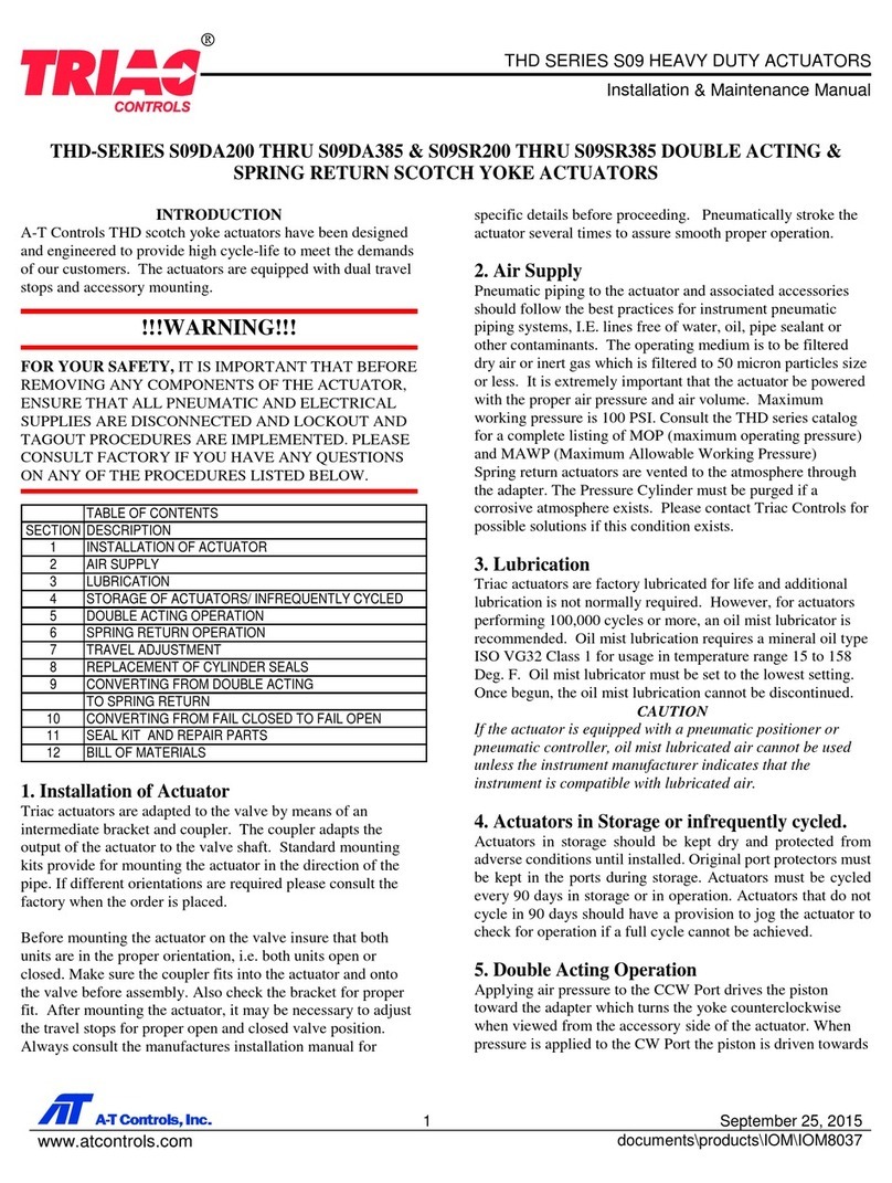
Electric Actuator with worm drive
Installation & Maintenance Manual
1 May 28, 2019
www.atcontrols.com IOM08069
KE SERIES ELECTRIC ACTUATOR
ATTENTION
For safe and proper operation, please read this manual carefully before using.
1. Pre-caution
After receiving actuator, please check the following matters.
a) Packing and documents ①product list ②wiring diagram
b) Inspection report; Nameplate; Electrical wiring diagram is consistent with
purchase
c) Cable interface and seal method after completion of electrical wiring.
Notice: The contents in this manual are subject to change without
individual notice.

KE SERIES
Electric Actuator with worm drive
Installation & Maintenance Manual
2 May 28, 2019
www.atcontrols.com IOM08069
2. Part Name
Sight glass cover
Motor
Sight glass
body
Terminal board
worm
worm gear
Output shaft
bearing
Gear box cover
Transmission gear
Motor endcap
Rotor spindle
Indicator dial

KE SERIES
Electric Actuator with worm drive
Installation & Maintenance Manual
3 May 28, 2019
www.atcontrols.com IOM08069
3. Performance features
3.1 Housing
Aluminum alloy housing. Anodized and polyester powder coated for strong
corrosion resistance. Protection class IP67.
3.2 Motor
Small size squirrel-cage motor with large torque and low inertia. Insulation class F
and built-in overheat protection switch to prevent the motor from overheating.
3.3 Manual operation
Safe and reliable handle design for easy manual operation. Power must be "OFF"
before manual operation. Clip on side of actuator housing to hold the handle when
it is not being used.
3.4 Indicator
Indicator installed on the central axis to show valve position. The convex lens
design makes it easier to observe without water collecting on the surface of the
indicator.
3.5 Heater
Heater is used to control the temperature and avoid internal moisture condensation
caused by temperature or weather changes. Keep electric elements dry.
3.6 Seal
Standard product protection grade is IP67.
3.7 Limit switch
Electronic open/close position limit switch controlled by easy to adjust cam with
accurate and convenient position setting. Set screw prevents unintended
movement of cam.
3.8 Self-locking
The high precision worm and gear mechanism has high efficiency and can output
large torque. Its self-locking function prevents reverse travel. Transmission part is
stable and reliable, no need for additional grease.
3.9 Cover bolt
Captive cover bolts stay attached to cover when removed.
3.10 Installation
Mounting base is according to ISO5211 / DIN3337. Can be installed in both vertical
and horizontal installation.
3.11 Circuit
Control circuit conforms to single or three-phase power supply standard. Circuit
layout is simple and with compact terminals. Can effectively satisfy a variety of
additional functional requirements.
3.12 Mechanical Stop
Mechanical open/close travel stop screw is easily adjustable, safe and reliably
secured by locking nut/washer.

KE SERIES
Electric Actuator with worm drive
Installation & Maintenance Manual
4 May 28, 2019
www.atcontrols.com IOM08069
4. Sizing
KE Series electric actuator output torque ranges from 440 in-lbs to 3500 in-lbs and can
fit a variety of valves (ball valve, butterfly valve, etc.) and damper baffle, etc.
(model) KE-440 KE-880 KE-1700 KE-3500
(Output Torque) 440 in-lbs 880 in-lbs 1700 in-lbs 3500 in-lbs
(Operating time) 30s 30s 40s 40s
(Rotary Angle) 0~90°(270°for option)
(Motor Power) 20W 25W 40W 90W
Power Supply DC24V AC110V/AC220V/AC380V
Withstand Voltage DC24V - 500VDC for 60S AC110V/AC220V/AC380V - 1500VDC for 60S
Protection Class IP67
Conduit Entry (2) M18 x 1.5 (2) M18 x 1.5 CABLE GLAND
Limit Switch Electric: close/open limit switch
Manual work: mechanical limit
Installation Location
at any angle
Ambient Temperature -20℃~60℃
Note:
1) Above table is for reference only.
2) Sizing should be done after carefully reviewing the valve, temperature,
characteristics of fluid, etc.
3) For applications under abnormal conditions such as high and low
temperature, seawater, severe corrosion and high vibration, please consult
with factory before selecting actuator.
4) Decisions by user ignoring our recommendation, we are not responsible for it.
5. Mounting and adjusting
1. Installation
1) This product is not explosion-proof. Do not use it in an environment with
flammable or corrosive gas.
2) Consult factory in advance if installing in area where actuator may be
submerged.
3) Allow space for wiring, maintenance and for manual operation of actuator.
4) Use a protection cover to avoid rain and/or direct sunlight.
5) Typical installation direction; indicator window to the top.

KE SERIES
Electric Actuator with worm drive
Installation & Maintenance Manual
5 May 28, 2019
www.atcontrols.com IOM08069
2. Ambient temperature - Medium temperature
1) When the environment temperature is below freezing, add desiccant heater
inside the actuator.
2) When fluid temperature is below freezing, the bracket connected with the valve
shall special process.
3. Assembly with valve
Assembly procedure
1) Be sure that power is off before making manual operation.
2) Confirm that valve can turn smoothly by hand, then position it at full close.
3) Bolt bracket to valve if needed.
4) Mount actuator to the bracket. Keep bolts loose.
5) Position the actuator at 0° (close). Join the output shaft and the valve stem with
couplings.
6) Tighten the bolts.
7) Check with the attached crank handle if the valve will turn.
Actuator mounting base is in accordance with ISO5211 standard. If the valve also
conforms to the standard, direct mount may be possible. If valve does not conform
to standard, an assembly bracket is needed.
4. Adjustment
1) Adjustment of Stroke limit (Figure 15,17)
Turn valve to the full closed position. Loosen set screw on cam and rotate cam to
engage the limit Switch (CLS). Tighten set screw to secure cam in place. Repeat
procedure to set the open position.
2) Adjustment of mechanical stop
Loosen nuts on mechanical stops and back out stop limit set screws several turns.
Move actuator to the full-closed position. Tighten set screw on right until it stops.
Reverse the set screw two full rotations then tighten the nut. Set the full-open
position the same way. See Figure16
3) Adjustment of potentiometer
Potentiometer provides feedback signal in the actuators using three terminals. ②
wiper arm of potentiometer. ① terminal which resistance between wiper arm
decreases as actuator is open. ③ terminal which resistance between wiper arm
decreases as actuator is closed. (Note: The resistance should not pass over 0Ω as
this will cause position measurement error). Rotate valve to the full open position.
Measure resistance between ② and ① . Rotate the potentiometer gear to adjust
the resistance to between 35 Ω and 60 Ω. (Figure 17)

KE SERIES
Electric Actuator with worm drive
Installation & Maintenance Manual
6 May 28, 2019
www.atcontrols.com IOM08069
5. Test Operation
A. Manual Operation
Remove power off before making manual operation. Insert the manual handle into
the hexagonal hole underneath the rubber cap.
Note: Continuing to turn the actuator once the full open or full closed
mechanical stop is reached will result in damage to other parts. Avoid using
excessive force when turning with manual handle.
B. Power Operation
Before making power operation:
* Confirm that the indication on the position meter and the valve opening match
each other.
* Confirm that the circuits are properly wired, also that the unit operates in correct
direction with external switches.
1)Check the wiring diagram, power supply, input/output signal correctly.
2)Don’t change the internal wiring
3)Please check the rotating direction if the power supply is three-phase
3.1)Make sure the actuator is in the on/off position, turn on the power and
input the open signal
3.2)If the actuator runs to the open direction, it means the wiring is correct.
3.3)If not, switch 2 of the phase wires.
4)Actuator must not continuously operate for more than 15 minutes
6. Maintenance & Lubrication
Major parts are lubricated with long life Molybdenum base grease before shipment.
Lubrication is in principle not required.
When re-starting operation after a long period of rest, confirm the following.
* Cut power off, confirm by manual operation that valve moves smoothly.
* Open body cover and check that there is no condensation inside the unit, or that
there are no problem with wiring.
Note: After checking, secure the cover to prevent water ingress.

KE SERIES
Electric Actuator with worm drive
Installation & Maintenance Manual
7 May 28, 2019
www.atcontrols.com IOM08069
7. Other
1) The actuator or the brochure shows the reference wiring diagram.
2) Please refer to the specification of Actuator module parts for modulating
instructions.
6. Trouble Shooting
Trouble Cause Solution
Actuator doesn’t
work at all
Check if power is on Power on
Wiring is not correct or is loose
Wire correctly and make
sure wires are tightly
connected
Voltage is too low or motor and
supplied power are different
Check motor power and
supplied power
Coil of motor is damaged Change the motor
Capacitor is damaged Change the capacitor
Open/close indicator
light doesn’t work
Indicator light is broken Change the indicator light
Micro switch bad action Change Micro switch
The motor does not
stop when it run to
limit position
Micro switch bad action Change Micro switch
The mechanical stop is set before
electrical limit Adjust Mechanical Stop
A-T Controls product, when properly selected, is designed to perform its intended function safely during its useful life.
However, the purchaser or user of A-T Controls products should be aware that A-T Controls products might be used in
numerous applications under a wide variety of industrial service conditions. Although A-T Controls can provide general
guidelines, it cannot provide specific data and warnings for all possible applications. The purchaser / user must therefore
assume the ultimate responsibility for the proper sizing and selection, installation, operation, and maintenance of A-T
Controls products. The user should read and understand the installation operation maintenance (IOM) instructions
included with the product, and train its employees and contractors in the safe use of A-T Controls products in connection
with the specific application.
While the information and specifications contained in this literature are believed to be accurate, they are supplied for
informative purposes only. Because A-T Controls is continually improving and upgrading its product design, the
specifications, dimensions and information contained in this literature are subject to change without notice. Should any
question arise concerning these specifications, the purchaser/user should contact A-T Controls.
For product specifications go to http://download.a-tcontrols.com/
A-T Controls, Inc. • 9955 International Boulevard, Cincinnati, OH 45246 • Phone: (513) 530-5175 • www.atcontrols.com
This manual suits for next models
4
Table of contents
Other TRIAC Controllers manuals
Popular Controllers manuals by other brands

hogar
hogar CEREBRO PRO manual

National Instruments
National Instruments GPIB GPIB-ENET/100 Getting started

Johnson Controls
Johnson Controls PENN ACT2 Technical bulletin

THORLABS
THORLABS TDC001 user guide

enphase
enphase IQ System Controller 3 INT Quick install guide

Rain Bird
Rain Bird ESP-LXIVM Series Device Installation Guidelines