manuals.online logo
Brands
  1. Home
  2. •
  3. Brands
  4. •
  5. TriangleTube
  6. •
  7. Boiler
  8. •
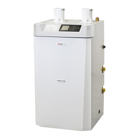
  9. TriangleTube Prestige Solo 399 User manual

TriangleTube Prestige Solo 399 User manual

restige SOLO 299/399
ACVMax Boilers
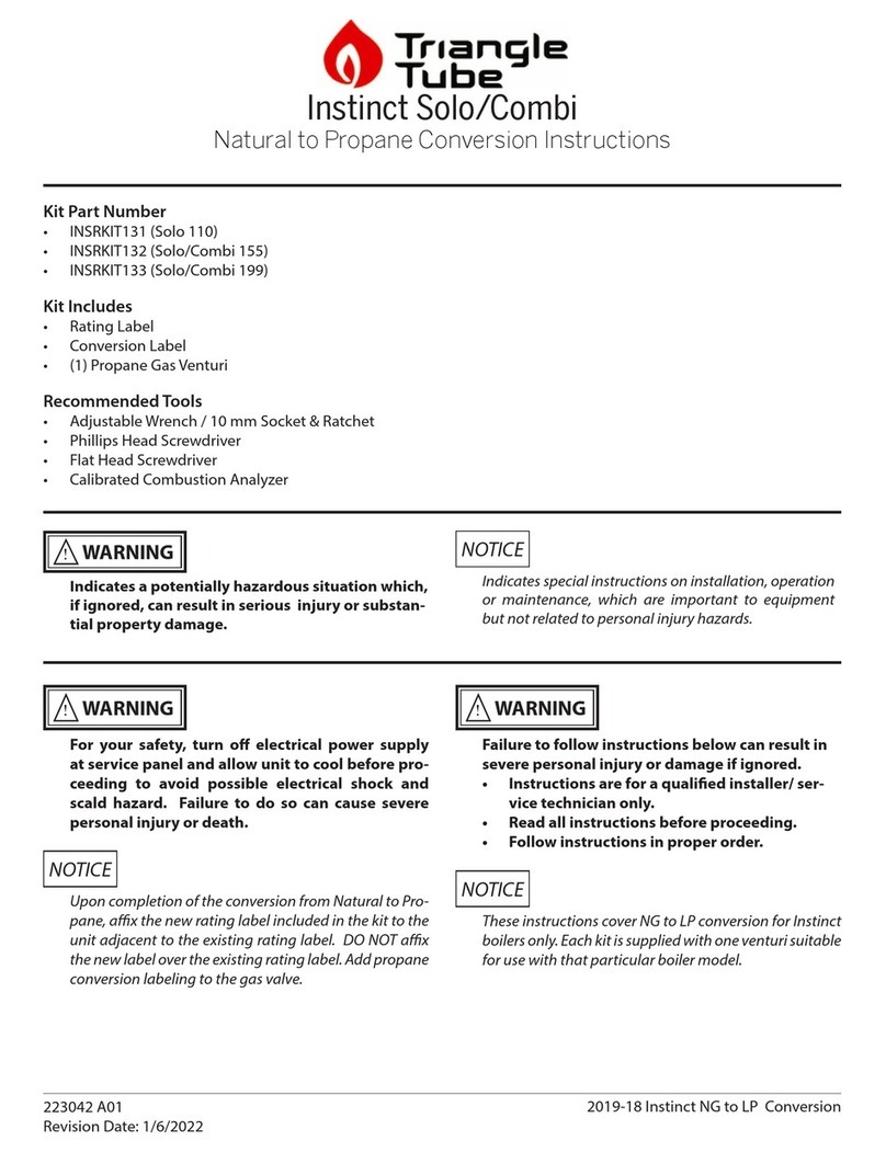
Natural to ropane Instructions
1
Failure to follow instructions below can
result in substantial property damage, seri-
ous injury, or death.
• Instructions are for a qualified installer
or service technician.
• Read all instructions before proceeding.
• Follow instructions in proper order.
For your safety, turn off electrical power
supply at service panel before proceeding to
avoid possible electrical shock hazard.
Failure to do so can result in substantial
property damage, serious injury, or death.
Upon completion of the conversion from
Natural Gas (NG) to ropane (L ), affix the
new rating label included in the kit to the
unit adjacent to the existing rating label. DO
NOT affix the new label over the existing rat-
ing label. Add propane conversion labeling to
the gas valve.
These instructions cover NG to L conversion
for ACVMax controlled restige Solo 299 &
399 boilers only. Each kit is supplied with one
orifice suitable for use with that particular
boiler model.
NOTICE
NOTICE
WARNING
WARNING
Indicates a potentially hazardous situation
which, if ignored, can result in substantial
property damage, serious injury, or death.
Indicates special instructions on installa-
tion, operation or maintenance, which are
important to equipment but not related to
personal injury hazards.
NOTICE
WARNING
Applicable Kit art Number:
- PARKIT67
Kit Includes:
- Rating Label
- Conversion Label
- (1) Propane Gas Orifice
- T-25 Torx Wrench
Recommended Tools
- Adjustable Wrenches
- Phillips-Head Screwdriver
- Flat-blade Screwdriver
- Calibrated Combustion Analyzer
restige SOLO 299/399 - ACVMax Boilers
Natural to ropane Instructions
2
1.0 Installation of the ropane Orifice
1. Turn off the electrical power supply to the boiler.
2. Close the manual gas shut off valve to the unit.
3. Remove the front panel of the Prestige by
removing the screws along the bottom edge of
the unit. Pull the bottom of the panel forward
and then lift up to remove the front panel from
the unit.
4. Remove the air inlet elbow (Fig 1, Item 1) from
the venturi using a twist and pull motion.
5. Remove four (4) electrical plugs and one (1)
ground wire connection from gas valve.
6. Disconnect the gas supply piping inside the
Prestige enclosure at the brass union located
just above the gas valve. See Fig. 1.
7. Remove the four (4) T-25 Torx head screws used to
mount the gas supply piping to the bottom of the gas
valve. Do not discard the screws. Remove the gas
valve assembly from the gas piping. See Fig. 1.
8. Remove the four (4) T-25 Torx head screws
attaching the brass union collar to the top of the
gas valve. Do not discard the screws. Remove
the brass natural gas orifice from the underside
of the brass union collar. See Fig. 2.
9. Install the appropriate brass propane orifice
from Table 1 in the gasket between the brass
union collar and the venturi. The rubber o-ring
must remain attached to the brass union collar.
See Fig. 2.
1. Air Inlet Elbow
2. T-25 Torx Head Screws (Gas Valve to Gas
Piping)
3. Gas Valve
4. Brass Union
Fig. 1: restige Gas Valve/ iping Assembly
2
3
41
Fig. 2: Orifice Location
1. T-25 Torx Head Screws (Union to Gas Valve)
2. Gas Valve
3. Orifice
4. Orifice O-Ring
Table 1: ropane Gas Orifice
2
1
3
4
Model Orifice Size
Solo 299/399 0.315 inch (8.0 mm)
restige SOLO 299/399 - ACVMax Boilers
Natural to ropane Instructions
3
Failure to retain both rubber o-rings on the
brass union collar will cause an improper seal
between the piping and gas valve resulting in a
potential risk of a gas leak. Any potential gas
leakage can result in substantial property dam-
age, serious injury, or death.
Ensure the proper orifice for the model is installed
per Table 1 on page 2. Failure to comply will affect
input rate and combustion of the boiler which can
result in substantial property damage, serious
injury, or death.
10. Reassemble the brass union collar onto the gas
valve using the four (4) T-25 Torx head screws.
Ensure the o-rings are properly placed and in
good condition.
11. Place the gas valve between the brass union and
the gas supply piping. Retighten the union just
above the gas valve and install the four (4) T-25
Torx head screws to attach the gas supply pip-
ing to the gas valve.
12. Reconnect the gas valve electrical connections
as shown in Fig. 3.
13. Open the manual gas shut off valve. Before
placing the Prestige boiler back into operation
check and test all gas connections for leaks.
Repair leaks if found.
Do not check for gas leaks with an open flame.
Use a bubble test. Failure to check for gas leaks
can result in substantial property damage, seri-
ous injury, or death.
14. Reattach the air inlet elbow to the venturi.
15. Replace the front jacket panel and secure with
screws.
16. Turn on the electrical power supply to the
Prestige boiler and return the unit back to service.
WARNING
WARNING
WARNING
2
1
3
45
Fig. 3: Gas Valve Electrical Connections
1. Single White Wire
2. Single Black Wire
3. Double White Wire
4. Double Black Wire
5. Double Green Wire
restige SOLO 299/399 - ACVMax Boilers
Natural to ropane Instructions
4
2.0 Combustion Test and Adjustments
1. The installer MUST perform a complete com-
bustion check to ensure the following combus-
tion levels in Tables 2 and 3 are met at high and
low input firing rates and the burner is operating
at optimum conditions.
Table 2: Recommended ropane Combustion Settings
The combustion testing and adjustments
must be performed by a qualified installer,
service agency or the gas supplier. All com-
bustion measurements must be performed
with calibrated equipment to ensure proper
readings and accuracy.
Failure to perform a complete combustion
test at both high and low input rates may
result in incomplete combustion and the pro-
duction of carbon monoxide, which can
result in substantial property damage, seri-
ous injury, or death.
The combustion levels should be measured at
high firing rate. If the combustion levels are
not within the range given in Table 2 for Low
Fire after adjusting High Fire, shut the boiler
down and contact Triangle Tube Technical
Support Department. Failure to comply
with this requirement can result in substan-
tial property damage, serious injury, or
death.
The gas valve outlet pressure is factory set to the
correct value and does not require field adjust-
ment or measurement. Measurement or adjust-
ments could result in damage to the gas valve
and can result in substantial property damage,
serious injury, or death.
2. Press the round I STALLER button. See Fig.
4.
3. Enter the installer access code “054” by using
the LEFT and RIGHT buttons to select a digit
and the U and DOWN buttons to change the
digit. Press the OK button to enter the access
code.
4. Press the RIGHT button to highlight the
Manual Operation icon then press the OK
button.
5. Press the OK button while the FA icon is
highlighted to manually fire the burner and
power the CH1 circulator (see Fig. 5)
WARNING
WARNING
WARNING
WARNING
DHW Demand
Target = 186°F
Installer Button
Fig. 4: ACVMax Navigation Buttons
Manual Operation
Released
O
O
O
CH1
FAN
DHW
CH2
Fig. 5: ACVMax Manual Operation
PA 299 PA 399
High Fire
CO2Range 10.7 to 12.0% 10.4 to 11.4%
CO2Target 11.0%
O2Range 2.7 to 4.7% 3.7 to 5.2%
O2Target 4.2%
Low Fire
CO2Range
0.5 to 0.6%
Lower than
H.F. CO2
O2Range
0. to 0.9%
Higher than
H.F. O2
CO Max 150 ppm
An adequate CH load must be present to dis-
sipate the heat generated during the combus-
tion test. If an adequate CH load is not avail-
able an indirect water heater can be used to
dissipate the heat by creating a DHW call
which will enable the DHW circulator.
6. Press the RIGHT button to adjust the firing rate
to 100% (high fire). Hold down the RIGHT
button to rapidly increase the firing rate.
7. If the combustion levels during high fire are
outside the recommended combustion settings
adjust the THROTTLE SCREW (see Fig. 6)
using a flat-blade screwdriver as follows:
Counter-clockwise adjustment of the THROT-
TLE SCREW at High Fire (100% firing rate):
O2decreases and CO2increases
Clockwise adjustment of the THROTTLE
SCREW at High Fire (100% firing rate):
O2increases and CO2decreases
8. Once the combustion level is set at high fire,
manually place the boiler into low fire mode by
pressing the LEFT button to adjust firing rate
down to 1% (low fire) to verify low fire com-
bustion settings.
9. If the combustion levels (O2& CO2) during
low fire are outside the recommended combus-
tion settings in Tables 2 & 3, contact Triangle
Tube Technical Support Department for assis-
tance.
10. Press the OK button while the fan icon is high-
lighted to shutdown the burner.
11. Press the LEFT or RIGHT button to highlight
the home screen icon to exit the service
mode.
NOTICE
restige SOLO 299/399 - ACVMax Boilers
Natural to ropane Instructions
5
Fig. 6: Combustion Adjustment - restige Burner
1. Throttle Screw
2016-22 Prestige ACVMax 299-399 G to LP
Revised Date: 3/29/2016
1

Other manuals for Prestige Solo 399

1

This manual suits for next models

2

Other TriangleTube Boiler manuals

TriangleTube Challenger Manual

TriangleTube

TriangleTube Challenger Manual

TriangleTube Instinct User manual

TriangleTube

TriangleTube Instinct User manual

TriangleTube Prestige Excellence Instruction Manual

TriangleTube

TriangleTube Prestige Excellence Instruction Manual

TriangleTube Prestige Solo 60 User manual

TriangleTube

TriangleTube Prestige Solo 60 User manual

TriangleTube Instinct  COMBI 155 User manual

TriangleTube

TriangleTube Instinct COMBI 155 User manual

TriangleTube Challenger Manual

TriangleTube

TriangleTube Challenger Manual

TriangleTube PRESTIGE Excellence 110 Instruction Manual

TriangleTube

TriangleTube PRESTIGE Excellence 110 Instruction Manual

TriangleTube Prestige Excellence Manual

TriangleTube

TriangleTube Prestige Excellence Manual

TriangleTube Prestige PARKIT101 User manual

TriangleTube

TriangleTube Prestige PARKIT101 User manual

TriangleTube CHALLENGER CC 85 Manual

TriangleTube

TriangleTube CHALLENGER CC 85 Manual

TriangleTube Prestige Supplement - Type 5 MCBA User guide

TriangleTube

TriangleTube Prestige Supplement - Type 5 MCBA User guide

TriangleTube Instinct FSB SOLO 110 Instruction Manual

TriangleTube

TriangleTube Instinct FSB SOLO 110 Instruction Manual

TriangleTube prestige User manual

TriangleTube

TriangleTube prestige User manual

TriangleTube Prestige Excellence Instruction Manual

TriangleTube

TriangleTube Prestige Excellence Instruction Manual

TriangleTube Prestige Solo 399 User manual

TriangleTube

TriangleTube Prestige Solo 399 User manual

TriangleTube Prestige Solo 60 User manual

TriangleTube

TriangleTube Prestige Solo 60 User manual

TriangleTube Instinct FSB User manual

TriangleTube

TriangleTube Instinct FSB User manual
TriangleTube Instinct  SOLO 155 User manual

TriangleTube

TriangleTube Instinct SOLO 155 User manual

TriangleTube Prestige Solo 250 User manual

TriangleTube

TriangleTube Prestige Solo 250 User manual

TriangleTube Instinct  SOLO 155 User manual

TriangleTube

TriangleTube Instinct SOLO 155 User manual

TriangleTube Prestige Solo 60 Instruction Manual

TriangleTube

TriangleTube Prestige Solo 60 Instruction Manual

TriangleTube Instinct Series Guide

TriangleTube

TriangleTube Instinct Series Guide

TriangleTube Prestige Solo Manual

TriangleTube

TriangleTube Prestige Solo Manual

TriangleTube CHALLENGER CC 85 User manual

TriangleTube

TriangleTube CHALLENGER CC 85 User manual

Popular Boiler manuals by other brands

Lochinvar KnightXL KBN400 Installation & operation manual

Lochinvar

Lochinvar KnightXL KBN400 Installation & operation manual

Worcester Greenstar 12Ri instruction manual

Worcester

Worcester Greenstar 12Ri instruction manual

Stropuva S7 TECHNICAL PASSPORT, INSTALLATION AND MAINTENANCE INSTRUCTION

Stropuva

Stropuva S7 TECHNICAL PASSPORT, INSTALLATION AND MAINTENANCE INSTRUCTION

BENSON JETSTREME 4+ instruction manual

BENSON

BENSON JETSTREME 4+ instruction manual

Abode PROBOIL.2X User's installation guide

Abode

Abode PROBOIL.2X User's installation guide

Ferroli ECONCEPT TECH 25 C Instructions for use, installation and maintenance

Ferroli

Ferroli ECONCEPT TECH 25 C Instructions for use, installation and maintenance

Alternate Heating WC40 Installation and operator's manual

Alternate Heating

Alternate Heating WC40 Installation and operator's manual

Sime Dewy 30 HE FS Installation and servicing instructions

Sime

Sime Dewy 30 HE FS Installation and servicing instructions

Navien NHB-110 User's information manual

Navien

Navien NHB-110 User's information manual

Alladin-Air SFL installation instructions

Alladin-Air

Alladin-Air SFL installation instructions

Vaillant VWZ MWT 150 Installation instructions and instructions for use

Vaillant

Vaillant VWZ MWT 150 Installation instructions and instructions for use

Lochinvar NOBLE NKB 80-199 Installation & service manual

Lochinvar

Lochinvar NOBLE NKB 80-199 Installation & service manual

IDEAL 36 Range guide

IDEAL

IDEAL 36 Range guide

Smith GSX SERIES User's information manual

Smith

Smith GSX SERIES User's information manual

Sime PLANET 25 OF C manual

Sime

Sime PLANET 25 OF C manual

DeDietrich MPX 28/33 BIC instruction manual

DeDietrich

DeDietrich MPX 28/33 BIC instruction manual

American Standard GRWF130A94A0A installation guide

American Standard

American Standard GRWF130A94A0A installation guide

Radiant R2K 34 RAIN Use manual

Radiant

Radiant R2K 34 RAIN Use manual

manuals.online logo
manuals.online logoBrands
  • About & Mission
  • Contact us
  • Privacy Policy
  • Terms and Conditions

Copyright 2025 Manuals.Online. All Rights Reserved.