manuals.online logo
Brands
  1. Home
  2. •
  3. Brands
  4. •
  5. TriangleTube
  6. •
  7. Industrial Equipment
  8. •
  9. TriangleTube TTP Series User manual

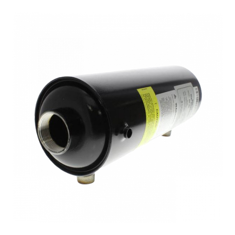
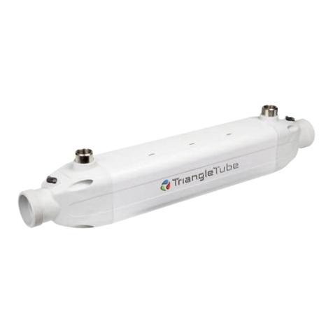
TriangleTube TTP Series User manual

Prior to installation and operation, read the entire guide completely. Failure to follow
proper instructions can result in severe personal injury, death or substantial proper-
ty damage.
CODE COMPLIANCE & RESTRICTIONS
• All piping and installations must conform with the instructions in this guide and where
applicable:
-Local, state, provincial, and national codes.
•Where recommendations in this guide differ from local, state or national codes, the
local, state or national codes take precedence.
• The heat exchanger is a single wall exchanger and complies with National Standard
Plumbing Code provided:
-Boiler/primary water (including additives) is practically non-toxic, having toxicity
rating or Class of 1 as listed in Clinical Toxicology of Commercial Products, and
- Boiler/primary water pressure is limited to maximum 30psig by approved relief
valve.
Single wall heat exchangers are permitted under Uniform Plumbing Code - Paragraphs L3.2
and L3.3 if they satisfy all of the following requirements:
1. The heat transfer medium is potable water or contains only substances, which are
recognized as safe by the U.S. Food and Drug Administration.
2. The pressure of the heat transfer medium is maintained less than the normal min-
imum operating pressure of the potable water system.
3. The equipment is permanently labeled to indicate that only additives recognized
as safe by the FDA shall be used in the heat transfer medium.
Operating Restrictions
Max. Operating Pressure (“E” model): 150 psig
Max. Operating Pressure: 450 psig
Max. Operating Temperature: 365ºF
Min. Operating Temperature: (-)320ºF
Plate Material: AISI 316 Stainless Steel
Brazing Material: 99.9% Copper
WARNING
BRAZED PLATE HEAT EXCHANGERS
TTP SERIES INSTALLATION GUIDE
RADIANT AND SNOW MELT APPLICATIONS
• Typically the circuit with the highest temperature and/or pressure should be connected
to the left side connections indicated by the color label.
•The circuit flows should be piped in a counter-flow arrangement.
• Use antifreeze specifically intended for hydronic heating systems. Inhibited propylene
glycol is recommended.
Do not use automotive ethylene glycol or any undiluted or petroleum-based
antifreeze. This can cause damage to the exchanger and system components result-
ing in severe personal injury, death or substantial property damage.
STEAM TO WATER APPLICATIONS
• Ensure the braze plate heat exchanger is mounted vertically to allow gravity drainage
of the condensate.
•The installer should use “Good Steam Practices” which includes a steam trap below the
unit and vacuum breakers.
• The steam circuit must enter the heat exchanger’stop connection, with the condensate
leaving the exchanger through the bottom connection.
•Provide steam traps at critical points i.e. in front of the control valve, to prevent “pool-
ing” of condensate.
WARNING
1240 Forest Parkway, Suite 100
West Deptford, NJ 08066
Tel: (856) 228 8881 - Fax: (856) 228 3584
E-mail: [email protected]
http://www.triangletube.com
2007-11 BP Inst. Guide 4/07
AVOID water hammering and other deformations caused by wet steam.
On low pressure steam systems or on applications with no-continuous processes,
place traps prior to the control valve and other critical points in the steam distribu-
tion system.
REFRIGERANT CONDENSER APPLICATIONS
• The heat exchanger must be mounted in the verti-
cal position to allow gravity drainage of the conden-
sate.
•The refrigerant gas must enter the heat exchanger
on the left side (indicated by the color label) using
the upper connection.
•The cooling water must enter the lower connection
of the exchanger and exit from the upper right con-
nection to maintain the counter-flow concept.
REFRIGERANT EVAPORATOR APPLICATIONS
•The heat exchanger must be mounted in the verti-
cal position.
•The refrigerant gas/liquid mixture must enter the
heat exchanger on the left side (indicated by the
color label) using the lower connection.
•The water must enter the upper right connection of
the exchanger and exit from the lower right con-
nection to maintain the counter-flow concept.
• The thermal expansion valve should be placed
close to the inlet connection of the heat exchanger.
The thermal expansion valve sensing bulb should
be placed on the refrigerant outlet approximately 12
to 24 inches from the heat exchanger.
• A pressure differential switch or flow switch must be installed to prevent possible
freeze-up due to loss of water flow.
NOTICE
• Water temperatures over 125ºFcan cause severe burns instantly or death from scalds.
• Feel water before bathing.
• Consumer Product Safety Commission and some states recommend temperature
settings of 130ºFor less. Setting thermostat higher than 130ºFwill increase the risk
of scald injury and cause personal injury or death.
• Water heated to a temperature suitable for clothes washing, dish washing and other
sanitizing needs will scald and cause permanent injury.
• Children and elderly, infirm, or physically handicapped persons are more likely to be
injured by hot water. Never leave them unattended in or near a bathtub. If anyone
using hot water in the building fits this description, or if state laws or local codes require
certain water temperature at hot water faucets, take special precautions:
- Install an automatic mixing valve at the exchanger or at each hot water faucet,
bath and shower.
- Use the lowest practical temperature setting.
- Check water temperature after any adjustments.
DANGER HOT WATER CAN SCALD!
F2
Water
Outlet
F4
Water
Inlet
Liquid
Outlet
F1 Gas
Inlet
F3
Fig. 3
F2
Water
Inlet
F4
Water
Outlet
Liquid
Inlet
F1 Gas
Outlet
F3
Fig. 4
• Provisions should be made in the piping to allow for thermal expansion or vibration.
• Provision in the system piping should be made to allow for back flushing / chemical
in-place cleaning, air elimination and draining of the system.
• To prevent fouling of the heat exchanger in harsh water conditions, a strainer with a
minimum 16 to 20 mesh is recommended on the inlet connection.
• To prevent fouling from debris, it is recommended to flush all piping prior to connec-
tion to the exchanger.
Blockage of the heat exchanger will lead to fouling or freezing of the heat exchang-
er resulting in severe personal injury, death or substantial property damage.
SOLDERING CONNECTIONS
Recommended soldering alloy: 30 - 55% silver
Recommended soldering alloy flow temperature: < 1200ºF
•Ensure flux material is non-corrosive to the materials of the heat exchanger.
• Ensure the connections are clean, free of dirt and oils, prior to applying the flux material.
• Use a wet towel or other means of a heat sink wrapped around the heat exchanger and
connection to prevent overheating.
• For refrigeration applications, flow dry nitrogen through the connections to prevent
oxidation.
WELDING CONNECTIONS
•Prepare the edge of the connection piping with a 30ºangle.
•Place the tapered piping into the exchanger connection and TIG or MIG weld the pipe
to the connection, filling the groove formed by the two edges.
-This method of welding minimizes the heat zone around the connection and
exchanger.
Do not heat the soldering / welding area higher than 1200ºF.Damage to the heat
exchanger brazing material could occur.
WARNING
WARNING
Water / Fluid Quality Restrictions
ph limit between 6 and 8
Chloride level less than 80 mg/L
Highly chlorinated water i.e. pool or spa applications
Mounting Heat Exchanger
• Heat exchanger should be mounted to allow suffi-
cient clearances for servicing.
• The heat exchanger should be mounted in the ver-
tical position with the color label on the left side of
the exchanger. When space and/or piping restric-
tions require another mounting position, the fol-
lowing guidelines should apply:
-In liquid to liquid applications the heat
exchanger can be mounted in any position
that does not permit entrapped air or gases
within the exchanger.
-For refrigerant and steam to water applica-
tions the heat exchanger must be mounted in
avertical position only.
• Never mount the heat exchanger with the connec-
tions facing downward in any application.
• Use brackets to support the heat exchanger when mounting.
•Install vibration absorbing material between the heat exchanger and the mounting
brackets to prevent damage to the exchanger.
Never support the heat exchanger solely by the piping. Insure the heat exchanger is
insulated from any severe vibrations. Failure to mount the heat exchanger properly
can result in severe personal injury, death or substantial property damage.
The heat exchanger may have sharp edges, excercise care in handling the exchang-
er during installation.
GENERAL PIPING
• Ensure all plumbing / piping meets or exceeds all local, state or national codes.
• Use isolation valves to isolate system components as required.
• Install union coupling for removal and servicing of the exchanger. Use dielectric
unions when connecting dissimilar materials such as copper and galvanized iron pipe.
CAUTION
WARNING
When using electrical welding circuit, connect the ground terminal to the joint tube, do
not connect to the back of the exchanger. Damage to the internal channels and braz-
ing material of the exchanger could occur.
THREADED CONNECTIONS
• Use Teflon or Mylar tape or other sealant on the male threaded part of the heat exchang-
er connection to prevent leakage.
• Use a two-wrench method when installing piping connections to the exchanger connection
to prevent over-torque stress and damage to the connection when tightening.
CLEANING AND MAINTENANCE
• The heat exchanger is typically maintenance free, requiring only routine cleaning as nec-
essary.
• To clean the heat exchanger, reverse flush the exchanger with water or a mild organic
acid (5% Phosphoric Acid or Oxalic Acid) solution. Ensure the flow rate of the flush is
greater than the operating flow rate.
•Flush the heat exchanger with fresh water when the cleaning process is completed. A
final rinse using a solution of 1 to 2% sodium hydroxide (NaOH) or sodium bicarbonate
(NaHCO3) ensures all acid is neutralized.
• When using a solution other than water, check with the solution manufacturer for com-
patibility to the exchanger’s material and always follow the manufacturer’s instructions
on use.
Toprevent damage to the heat exchanger and refrigerant components, do not chemi-
cally clean the refrigerant circuit of the heat exchanger.
DOMESTIC WATER APPLICATIONS
•Typically the circuit with the highest temperature and/or
pressure should be connected to the left side connections
indicated by the color label.
•The circuit flows should be piped in a counter-flow
arrangement.
• On instantaneous water heating applications (no available
storage) a flow switch must be used to prevent overheat-
ing of the heat exchanger.
WARNING
WARNING
Fig. 1 Recommended
Mounting Methods
F2
F4
F1
F3
Fig. 2

Other TriangleTube Industrial Equipment manuals

TriangleTube PRESTIGE Excellence Series User manual

TriangleTube

TriangleTube PRESTIGE Excellence Series User manual

TriangleTube MAXI-FLO MF 350 PT Series Manual

TriangleTube

TriangleTube MAXI-FLO MF 350 PT Series Manual

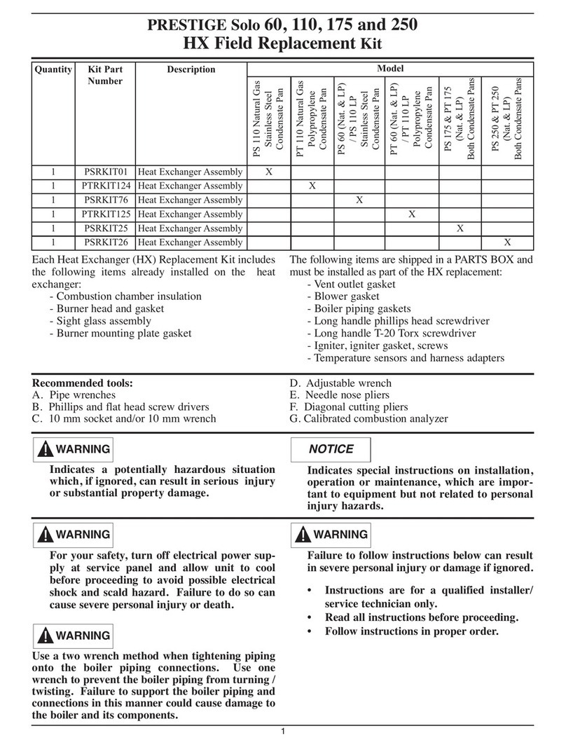
TriangleTube PSRKIT25 User manual

TriangleTube

TriangleTube PSRKIT25 User manual

TriangleTube MAXI-FLO MF-135 Manual

TriangleTube

TriangleTube MAXI-FLO MF-135 Manual

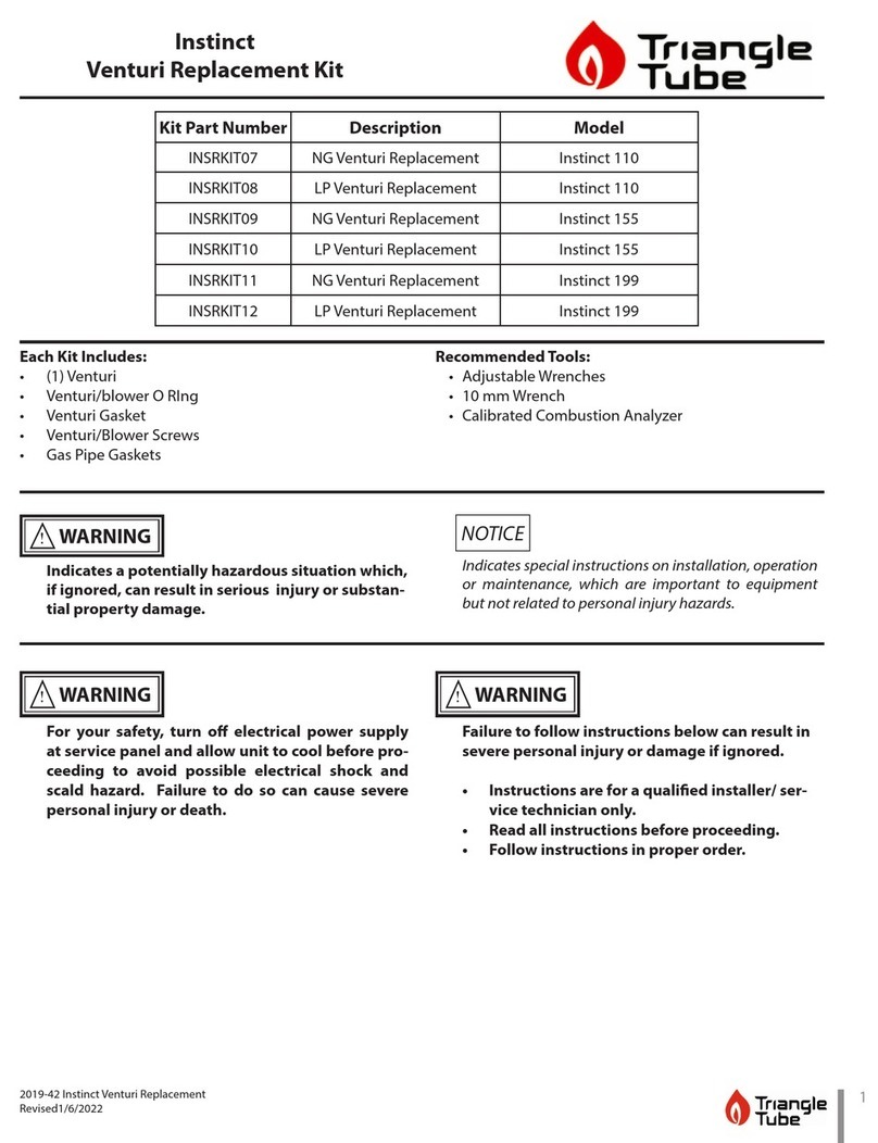
TriangleTube INSRKIT124 User manual

TriangleTube

TriangleTube INSRKIT124 User manual

TriangleTube Instinct 110 User manual

TriangleTube

TriangleTube Instinct 110 User manual

Popular Industrial Equipment manuals by other brands

DINA DNSR-2R Original instruction manual

DINA

DINA DNSR-2R Original instruction manual

Siemens SIMATIC S7-200 Getting started

Siemens

Siemens SIMATIC S7-200 Getting started

HOLZMANN MASCHINEN OFT 102 user manual

HOLZMANN MASCHINEN

HOLZMANN MASCHINEN OFT 102 user manual

Elsist SlimLine Picoface Hardware manual

Elsist

Elsist SlimLine Picoface Hardware manual

Eaton Bussmann Series manual

Eaton

Eaton Bussmann Series manual

ABB HT610550 Operation manual

ABB

ABB HT610550 Operation manual

BVA H1004AR instruction manual

BVA

BVA H1004AR instruction manual

Guyson KS MK3 300 Operation & maintenance manual

Guyson

Guyson KS MK3 300 Operation & maintenance manual

ABB HT580281 Operation manual

ABB

ABB HT580281 Operation manual

ISHIDA OMNi-4000 Film Feeder Replacement Manual

ISHIDA

ISHIDA OMNi-4000 Film Feeder Replacement Manual

ABB HT588272 Operation manual

ABB

ABB HT588272 Operation manual

Balluff BTL7-A/E501-M Series user guide

Balluff

Balluff BTL7-A/E501-M Series user guide

POWERTEX PGT-S2 user manual

POWERTEX

POWERTEX PGT-S2 user manual

FMS BKS010 operating manual

FMS

FMS BKS010 operating manual

Endress+Hauser CleanFit CPA 451 operating instructions

Endress+Hauser

Endress+Hauser CleanFit CPA 451 operating instructions

GSI Group 700 Bu/Hr owner's manual

GSI Group

GSI Group 700 Bu/Hr owner's manual

SMC Networks LESYH16-X171 Series Operation manual

SMC Networks

SMC Networks LESYH16-X171 Series Operation manual

ABB HT573826 Operation manual

ABB

ABB HT573826 Operation manual

manuals.online logo
manuals.online logoBrands
  • About & Mission
  • Contact us
  • Privacy Policy
  • Terms and Conditions

Copyright 2025 Manuals.Online. All Rights Reserved.