Nidec Avtron HS45 Series User manual

HS45 1
8901 E. PLEASANT VALLEY ROAD
•
INDEPENDENCE, OHIO 44131-5508
TELEPHONE: (1) 216-642-1230
•
FAX: (1) 216-642-6037
E-MAIL:[email protected]
•
WEB: www.avtronencoders.com
Nidec-Avtron Makes the Most Reliable Encoders in the World
When mounted to a machine shaft, the HS45 design eliminates the
need for shaft couplings, adapter flanges, or accessory mounting
faces. The high clamping-force collar holds the HS45 in place, even
under severe vibration & shock. A high-performance composite shaft
insert provides electrical isolation from motor shaft currents. The shaft
insert permits models to fit a range of shaft sizes from 5/8" to 1 1/8"
[16mm - 30mm]; additional sizes available upon request. An anti-
rotation arm prevents housing rotation while allowing for shaft end
float.
The HS45 utilizes magnetoresistive sensors. This proven technology
is ideal for rugged environments since it is immune to many
contaminants that cause optical encoders to fail. All of the HS45
electronics are potted, providing full protection against liquids.
The outputs are protected against short circuits and wiring errors.
DESCRIPTION
The Avtron Model HS45 is a heavy duty incremental encoder (also
known as tachometer or rotary pulse generator). Its output is directly
proportional to shaft position (pulse count) or speed (pulse rate). The
HS45 operates down to zero speed and can be used for both control
and instrumentation applications.
CAUTION
Do not utilize HS45 in hazardous locations which
require ATEX, UL, CUL, CSA, or other explosion protection
certification. HS45 is not certified for hazardous
locations. Use XR models for hazardous applications.
Encoder
Instructions
HS45
5/8-1 1/8" [16-30mm]
HOLLOW SHAFT
HS45 PART NUMBERS AND AVAILABLE OPTIONS
Model Bore Size
Left
Output
PPR
Right
Output
PPR
Line Driver Connector Options Tether Channels Modifications
HS45 Clamping
Collar Mount
U.S.
C- 5/8”
D- 3/4"
E- 7/8"
F- 1"
G- 1 1/8
U- All US Sizes
K- 1.375’
N- 1.118”
Clamping
Collar Mount
Metric
S- 16mm
T- 18mm
V- 19mm
W- 20mm
Y- 25mm
3- 30mm
Z- All Metric
Sizes
End of Shaft:
Center Bolt
Mount
L- 16mm
(no taper)
M- 17mm
(10:1 taper)
P- 20mm
J- 30mm
XX-None
BC-50
AF-60
AK-80
AG-100
AH-120
AA-128
AM-200
AL-240
AN-256
AP-300
AE-360
AC-400
AB-480
AQ-500
AR-512
AS-600
AU-720
AV-900
AJ-960
AW-1000
AY-1024
AZ-1200
CX-1500
A3-2000
A4-2048
A5-2500
AT-3072
A7-3600
AD-4096
A8-4800
A9-5000
A0-Special
XX-None
BC-50
AF-60
AK-80
AG-100
AH-120
AA-128
AM-200
AL-240
AN-256
AP-300
AE-360
AC-400
AB-480
AQ-500
AR-512
AS-600
AU-720
AV-900
AJ-960
AW-1000
AY-1024
AZ-1200
CX-1500
A3-2000
A4-2048
A5-2500
AT-3072
A7-3600
AD-4096
A8-4800
A9-5000
A0-Special
Note Dual
Output NA
with Foot
Mount Bracket
6- 5-24V in/out
(7272)
8- 5-24V in/out
(HX)
9- 5-24V in,
5V out (7272)
10 Pin MS Connector-
Small Encoder Pinout
A- Avtron/BEI Pinout, w/o plug
B- Dynapar HS35 Pinout, w/o plug
C- Avtron/BEI Pinout, mating plug
D-Dynapar HS35 Pinout, mating plug
Y-12” cable w/plug
X- None
Flat Styles:
A- Fan Cover
1/4” mount
D- Fan Cover
(T-bolt)
E- 4.5” NEMA
C-face
F- 8.5” NEMA
FC-face
Threaded Rod
Styles:
G- 70-500mm
w/bracket
P- 70mm fixed
w/screw
T- Fan Cover
70-500mm
w/T-bolt
Combinations:
H- Fan Cover
& 8.5”
C-face
M- Fan Cover
& 4.5”
C-Face
U- Universal
(includes
all styles)
Dual/Ganged
Encoders:
Y- Tether 2nd
encoder to
1st
(select any
tether from
above list for
first encoder)
A- All
A,B,A,B,Z,Z
(req’d for 8,
10 pin con-
nectors)
For 6,7
pin conns
only
B- A,B,A,B
(no marker)
E- A,B,Z
(single
ended)
F- A,B
(single
ended, no
marker)
D- A, A,
000- None
004- Super
Magnetic
Shielding
500- Add 100C
temperature
range to shaft
bores 5/8-1”
and 16mm-
25mm
6xx- Add over
speed switch
xx=speed
code
9xx- Specify cable
length xx=feet
max 33ft
(use w/ Option
“Q”,“W”, “Z”)
10 Pin MS Connector- Large Encoder Pinout
4-Avtron/Northstar Pinout, mating plug
6 Pin MS Connector- Small Encoder Pinout
E- Avtron/BEI Pinout, w/o plug
F- Dynapar HS35 Pinout, w/o plug
7 Pin MS Connector- Small Encoder Pinout
J- Avtron/BEI Pinout, w/o plug
K- Dynapar HS35 Pinout, w/o plug
M-4 foot cable w/o plug, channel B
Small EPIC Connector
P- Avtron pinout, w/mate
G- Northstar pinout w/mate
Q- Avtron pinout on remote base, 18” cable w/mate
Z- Avtron pinout on 18” cable w/mate
Terminal Box w/terminal strip
H- USA, 1/2” conduit
L- Europe w/cord grip
8 Pin M12 Connector
T- Global pinout, w/o plug
U- USA Pinout, w/o plug
12 Pin M23 Connector
2- Leine and Linde pinout, w/o plug
3- Hubner Pinout w/o plug
W- Cable 3’ (or special length)
R- Mini Twist Lock (Mini MS) w/ mating plug
V-
Mini Twist Lock (Mini MS) w/ mating plug (Reverse Phasing)
S- Mini Twist Lock (Mini MS) on 3’ cable w/mating plug
N-
Mini Twist Lock (Mini MS) w/o plug (Reverse Phasing)

HS45 2
Each HS45 has a two-phase output (A, B) 90° out of phase, with
complements (A, B), (A Quad B Output). A marker pulse with
complement (Z, Z) is also present.
The HS45 has a diagnostic package that includes Adaptive Electronics
and a Fault-Check output and red/green LED for local indication.
With this package, the HS45 can maintain itself, and provide an
alarm if there is a problem before the problem causes unscheduled
downtime.
ADAPTIVE ELECTRONICS
A perfect duty cycle consists of a waveform whose “high” and
“low” conditions are of the same duration (50%/50%). It is possible
over time for the duty cycle and edge separation to change due
to component drift, temperature changes, or mechanical wear.
The Adaptive Electronics extend the life of the HS45 by constantly
monitoring and correcting duty cycle and edge separation over time.
FAULT-CHECK
If the Adaptive Electronics reach their adjustment limit, the LED will
turn red and Fault-Check alarm will notify the drive and operator of
an impending failure. This output can occur before a failure, allowing
steps to be taken to replace the unit before it causes unscheduled
downtime. Fault-Check annunciation is available as an “alarm” output
through the connector.
SAFETY
The HS45 is not considered as a safety device and is not suitable for
connection into a safety system. The mechanical overspeed switch
(option 6xx) is suitable for connection into safety systems.
CAUTION
Do not disassemble mechanical overspeed option.
Doing so may modify the overspeed set point or cause
the switch to malfunction. If the factory seals are not
intact on the overspeed switch, do not use it--return to
the factory for service and calibration.
ELECTRICAL SPECIFICATIONS
A. Operating Power (Vin)
1. Volts............................ 5-24 VDC in
2. Current ....................... 100mA, nominal, plus cable load
B. Output Format
1. 2O/ & Comp ................ A,A
–, B,B
–(differential line driver)
2. Marker: ....................... 1/Rev Z, Z
–
C. Signal Type..................... Incremental, Square Wave, 50 +/-10%
................................... Duty Cycle.
D. Direction Sensing ........... O/ A leads O/ B for CW rotation as viewed
................................... from the back of the tach looking at the
................................... non-drive end of the motor.
E. Transition Sep. ............... 15% minimum
F. Frequency Range........... See below
G. PPR ................................ 3-2,500***
H. Line Driver Specs: .......... See table
I. Connectors: .................... See connector options on page 1
MECHANICAL
A. Shaft Inertia .................... 1.59 lb-in-sec2
B. Acceleration.................... 5000 RPM/Sec. Max.
C. Speed: ............................ 5000 RPM Max (also see overspeed)****
D. Weight: ........................... 10-12 lbs [4.5-5.5kg]
E. Vibration ......................... 20 Gs, 5-2000 Hz (any orientation)
F. Shock ............................. 100 Gs, any orientation
G. Shaft Engagement (clamp style)
5/8”-7/8” bore...................2” [51mm] min.
16-20mm bore..................51mm min.
1”- 1 1/8” bore..................1.75” [45mm] min.
25-30mm bore..................45mm min.
with overspeed switch......2.65” +/-0.05” [68mm +/-1.27mm]
****(Speed) Maximum RPM may be limited for PPR > 2,500 consult
factory with your application
ENVIRONMENTAL
Solid cast aluminum stator and rotor
Fully potted electronics, protected against oil and water spray
Operating Temperature:.......-40°C to +100°C.
(note for shaft codes C-F, S-Y, +85C or use option 500 = +100C)
MECHANICAL OVERSPEED SWITCH OPTION
A. Shaft Inertia .................... +0.0018 lb-in-sec2
B. Acceleration.................... 3600 RPM/Sec. Max.
C. Speed: ............................ 1.25 x Overspeed set point Max.
Minimum trip speed: 700 RPM
Maximum trip: 3600 RPM
Accuracy +/- 4% of trip point
Hysteresis: 40% of trip point
D. Weight:............................ +2.55 lbs [+1.16kg]
E. Vibration: ........................ 20 Gs, 5-2000 Hz (radial only)
F. Shock: ............................ 100Gs, any orientation
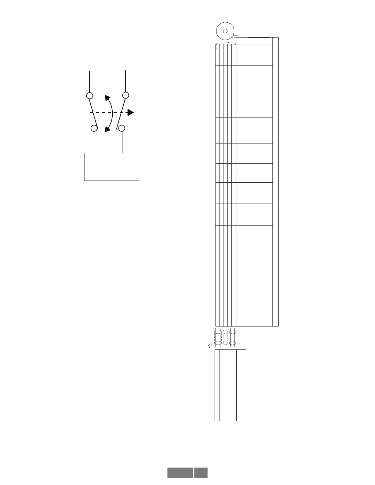
G. Electrical Contact (NO/NC Contact)
1. ................................... 6A/230VAC
2. .................................... 3A/380VAC
3. .....................................1A/125VDC
H. Operating Temperature:......-40°C to +100°C.
Frequency Range: @5V, @1m cable, 250 kHz Max
@24V, @300m cable, #8 output, 45 kHz Max
Max Cable Lenght: 300m
*** (PPR) Standard PPR is 5000. Consult factory with your application
for PPRs up to 25,000
A
B
Z
Timing Diagram (A leads B for CW rotation)
LINE DRIVER OPTIONS
Electrical Specifications 6 8 9 Units
Input Voltage 5-24 5-24 5-24 VDC
Nom Output Voltage 5-24 5-24 5 VDC
Line Driver 7272 HX 7272
Output Resistance Typ
13 75 13 ohms
Maximum Peak Current 1500 800 1500 mA
Maximum Average
Current 120 200 120 mA
Voh Typ VIN-1 VIN-1 VIN-1 VDC
Vol Typ 0.5 0.4 0.5 VDC
Cable Drive Capacity
1000’ @ 5V
500’ @ 12V
200’ @ 24V
1000’ 1000’ feet
Protection
Reverse
Voltage yes yes yes
Short
Circuit yes yes yes
Transient yes yes yes
Mis-Wiring yes yes yes
Alarm
+V(out) Output voltage equal to input voltage.
Alarm* Open collector, normally off, goes low on alarm,
sink 100mA max, 50VDC max
Marker One per revolution. Pulse width
1/4 AB Period. Gated with A&B High
LED
Green = Power on
Red = Alarm
Orange = Line Driver Shutdown (Due
to thermal overload or undervoltage)

HS45 3
Example 2. Alarm Output Using Separate 24 VDC Power Supply and Relay.
Applies to Model HS45 Encoders connector styles “H”, “L”, “P”, “Q”, “W”, “Z”, “4”
ALARM OUTPUT CONNECTION
Avtron HS45 encoders provide an alarm signal if maintenance is required under specific circumstances. Following are application
examples provided to help install the alarm output.
Example 1. Alarm output using +V(OUT). +V(OUT) is equal to +V, the encoder power supply.
NOTE: Alarm output is “low true”; i.e., goes to OV when active.
HS45
Remote Alarm
BLACK
RED
GREEN
YELLOW
BLUE
GRAY
ORANGE
WHITE
BROWN
VIOLET
OUTPUT OPTIONS
A
B
D
G
E
H
C
I
F
J
9
4
5
10
2
8
3
7
6
1
+V(OUT)
Z
Z
A
B
B
A
+V
COM
Vcc
OUT
COM
300 OHM
MIN.
GND
FUNCTION
ENCODER
ØB
ØA
ØA
ØB
4-16 VDC SOLID STAT E RELAY
LINE
DRIVER
{
FUNCTIONAL DIAGRAM
50 mA MAXIMUM
“W”“4”“P”,“Q”,
“Z”“H”, “L”
ALM
MARKER
MARKER COMPLEMENT
COMMON
+V (Encoder Power)
{
BLACK
RED
GREEN
YELLOW
BLUE
GRAY
ORANGE
WHITE
BROWN
VIOLET
“H”,“L”
OUTPUT OPTIONS
A
B
D
G
E
H
C
I
F
J
9
4
5
10
2
8
3
7
6
1
ALM
+V(OUT)
Z
Z
A
B
B
A
+V
COM
MARKER
MARKER COMPLEMENT
GND
FUNCTION
+V (Encoder Power)
COMMON
24
VDC
RELAY
+
-
POWER
SUPPLY 115 VAC
SINK 100 mA MAXIMUM,
WITHSTAND 50 VMAXIMUM
REFERENCED TO COMMON
ENCODER
FUNCTIONAL DIAGRAM
ØB
ØA
ØA
ØB
LINE
DRIVER
“W” “4” “P”,“Q”,
“Z”

HS45 4
WIRING DIAGRAMS
Avtron standard warranty applies. Copies available upon request.
Specifications subject to change without notice.
OPTION
“W”
(CABLE)
AABB B
OPTIONS
“A”, “B”, “C”, “D”
(10 PIN MS)
PINOUT
OPTIONS
“J”, “K”
(7 PIN MS)
BLACK
RED
GREEN
YELLOW
BLUE
GRAY
ORANGE
WHITE
BROWN
VIOLET
BROWN
VIOLET
BROWN
VIOLET
DIFFERENTIAL TWO PHASE WIRING APPLICATIONS
F
D
A
H
B
I
C
J
F
D
A
C
B
E
NC
NC
NC
NC
NC
NC
F
D
A
C
B
E
NC
NC
NC
NC
OPTIONS
“E”, “F”
(6 PIN MS) (8 PIN M12) (8 PIN M12)
(8 PIN M12) (8 PIN M12)
A
B
E
C
D
F
NC
NC
NC
NC NC NC
NC
NC
ØA, ØA
–
ØB, ØB
–
ØZ, ØZ
–
ØA, ØA
–
ØB, ØB
–
ØZ, ØZ
–
ØA, ØA
–
ØB, ØB
–ØA, ØA
–
ØB, ØB
–ØA, ØA
–
ØB, ØB
–
CHANNELS CONNECTOR
<<CONNECTED ON 18" CABLE
* NC ON CHANNEL OPTION “B”
<< CONNECTED ON 18" CABLE
1
2
3
4
5
6
7
8
7
2
1
3
4
5
6
8
OPTIONS
“T”
OPTIONS
“U”
OPTIONS<<
“U”
A
ØA, ØA
–
ØB, ØB
–
ØZ, ØZ
–
A
ØA, ØA
–
ØB, ØB
–
ØZ, ØZ
–
OPTION “W”
(CABLE)
A
OPTIONS
“A”, “B”, “C”, “D”
(10 PIN MS)
PINOUT
OPTIONS<<
“J”, “K”, “M”, “N”
(7 PIN MS)
RED
BLUE
GREEN
BLACK
ORANGE *
SINGLE ENDED TWO PHASE WIRING APPLICATIONS, WITH OR WITHOUT MARKER | NOT RECOMENDED FOR OUTPUT OPTION “8”
D
B
A
F
C*
D
B
A
F
C*
OPTIONS<<
“E”, “F”, “G”, “H”
(6 PIN MS)
B
D
E
A
C*
E, F
ØA, ØB, ØZ
E, F
ØA, ØB, ØZ
E, F
ØA, ØB, ØZ
CHANNELS CONNECTORS
* NC ON CHANNEL OPTION “F”
^ COMPLEMENTS INCLUDED BUT NOT USED
22
54
1
3
1
7
7
6
A
ØA, ØA
–^
ØB, ØB
–^
ØZ, ØZ
– ^
ØA, ØA
–
ØB, ØB
–
ØZ, ØZ
–
ØA, ØA
–
ØB, ØB
–
ØZ, ØZ
–
A
OPTION “W”
(CABLE)
OPTIONS
“A”, “B”, “C”, “D”
(10 PIN MS)
PINOUT
OPTIONS<<
“J”, “K”, “M”, “N”
(7 PIN MS)
BLACK
RED
GREEN
SINGLE ENDED SINGLE PHASE WIRING APPLICATIONS | NOT RECOMENDED FOR OUTPUT OPTION “8”
F
D
A
F
D
A
OPTIONS<<
“E”, “F”, “G”, “H”
(6 PIN MS)
A
B
E
ØA
(ØA
–INCLUDED
BUT NOT USED)
ØA
(ØA
–INCLUDED
BUT NOT USED)
ØA
(ØA
–INCLUDED
BUT NOT USED)
DDD
CHANNELS CONNECTORS
1
2
3
7
2
1
OPTIONS<<
“T”
OPTIONS<<
“U”
A
ØA
–, ØB,
ØB
–, ØZ, ØZ
–ØA
–, ØB,
ØB
–, ØZ, ØZ
–
A
(ØA
–, ØB,
ØB
–, ØZ, ØZ
–
INCLUDED BUT
NOT USED)
A
OPTIONS<<
“T”
AA AA
5NC
NC10
F
D
A
H
B
J
C
K
1
6
2
7
3
8
4
9
NC
NC
1
6
2
7
3
8
4
9
F
J
A
B
D
G
E
H
C
I
ØA, ØA
–
ØB, ØB
–
ØZ, ØZ
–
ØA, ØA
–
ØB, ØB
–
ØZ, ØZ
–
OPTIONS
“R”, “S<<”
(10 PIN
TWIST-LOCK)
OPTIONS
“P”, “Q ”,“Z<<
<< ”
(10 PIN
INDUSTRIAL)
D
B
A
F
6
3
2
1
4C
6
3
2
1
4
B
E
D
A
C
AA
ØA, ØA
–
ØB, ØB
–
ØZ, ØZ
–
ØA, ØA
–
ØB, ØB
–
ØZ, ØZ
–
OPTIONS
“P”, “V”,“Z<<”
OPTIONS
“R”, “S<<”
(10 PIN
INDUSTRIAL)
(10 PIN
TWIST-LOCK)
1
6
2A
F
D
1
6
2D
A
B
AA
ØA, ØA
–
ØB, ØB
–
ØZ, ØZ
–
ØA, ØA
–
ØB, ØB
–
ØZ, ØZ
–
OPTIONS
“P”, “V”,“Z<<”
OPTIONS
“R”, “S<<”
(10 PIN
INDUSTRIAL)
(10 PIN
TWIST-LOCK)
ØA, ØA
–
ØB, ØB
–
ØZ, ØZ
–
A
ØA, ØA
–
ØB, ØB
–
ØZ, ØZ
–
ØA, ØA
–
ØB, ØB
–
ØZ, ØZ
–
A
ØA, ØA
–
ØB, ØB
–
ØZ, ØZ
–
A
ØA, ØA
–
ØB, ØB
–
ØZ, ØZ
–
A
ØA, ØA
–
ØB, ØB
–
ØZ, ØZ
–
A
ØA, ØA
–
ØB, ØB
–
ØZ, ØZ
–
A
ØA, ØA
–
ØB, ØB
–
ØZ, ØZ
–
OPTIONS
(10 PIN MS)
A
5
10
1
6
2
7
3
8
4
9
ØA, ØA
–
ØB, ØB
–
ØZ, ØZ
–
OPTIONS
CONDUIT BOX
OPTIONS
CONDUIT BOX
OPTIONS
“G” “4”
OPTIONS
(12 PIN M23)
“2”
OPTIONS
(12 PIN M23)
“2”
OPTIONS
(12 PIN M23)
“2”
OPTIONS
(12 PIN M23)
“3”
OPTIONS
(12 PIN M23)
“3”
OPTIONS
(12 PIN M23)
“3”
“H”,“L”
(10 PIN
INDUSTRIAL)
OPTIONS
(10 PIN MS)
OPTIONS
“G” “4”
(10 PIN
INDUSTRIAL)
A
ØA, ØA
–
ØB, ØB
–
ØZ, ØZ
–
A
ØA, ØA
–
ØB, ØB
–
ØZ, ØZ
–
A
ØA, ØA
–
ØB, ØB
–
ØZ, ØZ
–
OPTIONS
(10 PIN MS)
OPTIONS
“G” “4”
(10 PIN
INDUSTRIAL)
NC
NC
NC
NC
NC
NC NC NC
NC
NC 5NC
NC10
NC
NC
F
J
6
3
2
1
4
5
10
12
5
1
10
3
2
7
12
8
6
10
3
NC
NC
NC
NC
NC
NC
NC
NC NC NC
NC
NC 5NC
NC10
NC
NC
F
J
1
10
12
2
7
2
1
6
5
10
6
10
12
NC
NC
A
ØA, ØA
–
ØB, ØB
–
ØZ, ØZ
–
A
ØA, ØA
–
ØB, ØB
–
ØZ, ØZ
–
NC
NC
10
12
6
5
8
1
3
4
2
7
10
12
8
1
5
6
3
4
ALM+
ALM
ALM+
ALM
ALM+
ALM
REF
SIGNAL
COM GND0V
+V
ØA
ØA
––
––
ØB
ØB
–
Z
Z
–
+Ub+E
2+
2-
0+
0-
K1- 1+
1-
K1+
––
K2+
K2-
K0+
K0-
ALM+
ALM
ALM+
ALM
REF
SIGNAL
+V
ØB
ØA
–
COM
OZ
+Ub
K2+
K1-
GND
K0+
ALM+
ALM
+E
2+
1+
0V
0+
ALM+
ALM
ALM+
ALM
ALM+
ALM
COM GND 0V
0A
+V +Ub
–
K1
+E
1+
REF
SIGNAL
“H”,“L”
OPTIONS
CONDUIT BOX
“H”,“L”
A
ØA, ØA
–
ØB, ØB
–
ØZ, ØZ
–

HS45 5
WIRING DIAGRAMS
OPTION
“W”
(CABLE)
AABB B
OPTIONS
“A”, “B”, “C”, “D”
(10 PIN MS)
PINOUT
OPTIONS
“J”, “K”
(7 PIN MS)
BLACK
RED
GREEN
YELLOW
BLUE
GRAY
ORANGE
WHITE
BROWN
VIOLET
BROWN
VIOLET
BROWN
VIOLET
DIFFERENTIAL TWO PHASE WIRING APPLICATIONS
F
D
A
H
B
I
C
J
F
D
A
C
B
E
NC
NC
NC
NC
NC
NC
F
D
A
C
B
E
NC
NC
NC
NC
OPTIONS
“E”, “F”
(6 PIN MS) (8 PIN M12) (8 PIN M12)
(8 PIN M12) (8 PIN M12)
A
B
E
C
D
F
NC
NC
NC
NC NC NC
NC
NC
ØA, ØA
–
ØB, ØB
–
ØZ, ØZ
–
ØA, ØA
–
ØB, ØB
–
ØZ, ØZ
–
ØA, ØA
–
ØB, ØB
–ØA, ØA
–
ØB, ØB
–ØA, ØA
–
ØB, ØB
–
CHANNELS CONNECTOR
<<CONNECTED ON 18" CABLE
* NC ON CHANNEL OPTION “B”
<< CONNECTED ON 18" CABLE
1
2
3
4
5
6
7
8
7
2
1
3
4
5
6
8
OPTIONS
“T”
OPTIONS
“U”
OPTIONS<<
“U”
A
ØA, ØA
–
ØB, ØB
–
ØZ, ØZ
–
A
ØA, ØA
–
ØB, ØB
–
ØZ, ØZ
–
OPTION “W”
(CABLE)
A
OPTIONS
“A”, “B”, “C”, “D”
(10 PIN MS)
PINOUT
OPTIONS<<
“J”, “K”, “M”, “N”
(7 PIN MS)
RED
BLUE
GREEN
BLACK
ORANGE *
SINGLE ENDED TWO PHASE WIRING APPLICATIONS, WITH OR WITHOUT MARKER | NOT RECOMENDED FOR OUTPUT OPTION “8”
D
B
A
F
C*
D
B
A
F
C*
OPTIONS<<
“E”, “F”, “G”, “H”
(6 PIN MS)
B
D
E
A
C*
E, F
ØA, ØB, ØZ
E, F
ØA, ØB, ØZ
E, F
ØA, ØB, ØZ
CHANNELS CONNECTORS
* NC ON CHANNEL OPTION “F”
^ COMPLEMENTS INCLUDED BUT NOT USED
22
54
1
3
1
7
7
6
A
ØA, ØA
–^
ØB, ØB
–^
ØZ, ØZ
– ^
ØA, ØA
–
ØB, ØB
–
ØZ, ØZ
–
ØA, ØA
–
ØB, ØB
–
ØZ, ØZ
–
A
OPTION “W”
(CABLE)
OPTIONS
“A”, “B”, “C”, “D”
(10 PIN MS)
PINOUT
OPTIONS<<
“J”, “K”, “M”, “N”
(7 PIN MS)
BLACK
RED
GREEN
SINGLE ENDED SINGLE PHASE WIRING APPLICATIONS | NOT RECOMENDED FOR OUTPUT OPTION “8”
F
D
A
F
D
A
OPTIONS<<
“E”, “F”, “G”, “H”
(6 PIN MS)
A
B
E
ØA
(ØA
–INCLUDED
BUT NOT USED)
ØA
(ØA
–INCLUDED
BUT NOT USED)
ØA
(ØA
–INCLUDED
BUT NOT USED)
DDD
CHANNELS CONNECTORS
1
2
3
7
2
1
OPTIONS<<
“T”
OPTIONS<<
“U”
A
ØA
–, ØB,
ØB
–, ØZ, ØZ
–ØA
–, ØB,
ØB
–, ØZ, ØZ
–
A
(ØA
–, ØB,
ØB
–, ØZ, ØZ
–
INCLUDED BUT
NOT USED)
A
OPTIONS<<
“T”
AA AA
5NC
NC10
F
D
A
H
B
J
C
K
1
6
2
7
3
8
4
9
NC
NC
1
6
2
7
3
8
4
9
F
J
A
B
D
G
E
H
C
I
ØA, ØA
–
ØB, ØB
–
ØZ, ØZ
–
ØA, ØA
–
ØB, ØB
–
ØZ, ØZ
–
OPTIONS
“R”, “S<<”
(10 PIN
TWIST-LOCK)
OPTIONS
“P”, “Q ”,“Z<<
<< ”
(10 PIN
INDUSTRIAL)
D
B
A
F
6
3
2
1
4C
6
3
2
1
4
B
E
D
A
C
AA
ØA, ØA
–
ØB, ØB
–
ØZ, ØZ
–
ØA, ØA
–
ØB, ØB
–
ØZ, ØZ
–
OPTIONS
“P”, “V”,“Z<<”
OPTIONS
“R”, “S<<”
(10 PIN
INDUSTRIAL)
(10 PIN
TWIST-LOCK)
1
6
2A
F
D
1
6
2D
A
B
AA
ØA, ØA
–
ØB, ØB
–
ØZ, ØZ
–
ØA, ØA
–
ØB, ØB
–
ØZ, ØZ
–
OPTIONS
“P”, “V”,“Z<<”
OPTIONS
“R”, “S<<”
(10 PIN
INDUSTRIAL)
(10 PIN
TWIST-LOCK)
ØA, ØA
–
ØB, ØB
–
ØZ, ØZ
–
A
ØA, ØA
–
ØB, ØB
–
ØZ, ØZ
–
ØA, ØA
–
ØB, ØB
–
ØZ, ØZ
–
A
ØA, ØA
–
ØB, ØB
–
ØZ, ØZ
–
A
ØA, ØA
–
ØB, ØB
–
ØZ, ØZ
–
A
ØA, ØA
–
ØB, ØB
–
ØZ, ØZ
–
A
ØA, ØA
–
ØB, ØB
–
ØZ, ØZ
–
A
ØA, ØA
–
ØB, ØB
–
ØZ, ØZ
–
OPTIONS
(10 PIN MS)
A
5
10
1
6
2
7
3
8
4
9
ØA, ØA
–
ØB, ØB
–
ØZ, ØZ
–
OPTIONS
CONDUIT BOX
OPTIONS
CONDUIT BOX
OPTIONS
“G” “4”
OPTIONS
(12 PIN M23)
“2”
OPTIONS
(12 PIN M23)
“2”
OPTIONS
(12 PIN M23)
“2”
OPTIONS
(12 PIN M23)
“3”
OPTIONS
(12 PIN M23)
“3”
OPTIONS
(12 PIN M23)
“3”
“H”,“L”
(10 PIN
INDUSTRIAL)
OPTIONS
(10 PIN MS)
OPTIONS
“G” “4”
(10 PIN
INDUSTRIAL)
A
ØA, ØA
–
ØB, ØB
–
ØZ, ØZ
–
A
ØA, ØA
–
ØB, ØB
–
ØZ, ØZ
–
A
ØA, ØA
–
ØB, ØB
–
ØZ, ØZ
–
OPTIONS
(10 PIN MS)
OPTIONS
“G” “4”
(10 PIN
INDUSTRIAL)
NC
NC
NC
NC
NC
NC NC NC
NC
NC 5NC
NC10
NC
NC
F
J
6
3
2
1
4
5
10
12
5
1
10
3
2
7
12
8
6
10
3
NC
NC
NC
NC
NC
NC
NC
NC NC NC
NC
NC 5NC
NC10
NC
NC
F
J
1
10
12
2
7
2
1
6
5
10
6
10
12
NC
NC
A
ØA, ØA
–
ØB, ØB
–
ØZ, ØZ
–
A
ØA, ØA
–
ØB, ØB
–
ØZ, ØZ
–
NC
NC
10
12
6
5
8
1
3
4
2
7
10
12
8
1
5
6
3
4
ALM+
ALM
ALM+
ALM
ALM+
ALM
REF
SIGNAL
COM GND0V
+V
ØA
ØA
––
––
ØB
ØB
–
Z
Z
–
+Ub+E
2+
2-
0+
0-
K1- 1+
1-
K1+
––
K2+
K2-
K0+
K0-
ALM+
ALM
ALM+
ALM
REF
SIGNAL
+V
ØB
ØA
–
COM
OZ
+Ub
K2+
K1-
GND
K0+
ALM+
ALM
+E
2+
1+
0V
0+
ALM+
ALM
ALM+
ALM
ALM+
ALM
COM GND 0V
0A
+V +Ub
–
K1
+E
1+
REF
SIGNAL
“H”,“L”
OPTIONS
CONDUIT BOX
“H”,“L”
A
ØA, ØA
–
ØB, ØB
–
ØZ, ØZ
–
BREAK
(NC)
MAKE
(N0)
SAFETY
SYSTEM
125 VDC
OR
120 - 380 VAC
125 VDC
OR
120 - 380 VAC
MECHANICAL OVERSPEED SWITCH WIRING APPLICATIONS
Avtron standard warranty applies. Copies available upon request.
Specifications subject to change without notice.

HS45 6
CAUTION
Be careful not to damage clamping fingers of hollow
shaft during handling. Do not tighten clamping collar
before installation onto motor shaft.
WARNING
Installation should be performed only by qualified
personnel. Safety precautions must be taken to ensure
machinery cannot rotate and all sources of power are
removed during installation.
INSTALLATION
Refer to the back page of these instructions for outline and mounting
dimensions.
Equipment needed for installation
Supplied:
HS45 Encoder
Shaft Sizing Insert for all clamp style models
For 16mm center-bolt style ONLY: centering (tapered) ring
Optional:
Anti-Rotation Arm Kit
Thread Locker (blue)
Not Supplied:
Open Wrenches
“G”, “P”, “T”, ”U”-Tether: 9mm, 10mm
“D”, “E”,”F”,”H”,”M”,”U”-Tether: 7/16”,1/2”, 9/16”, 3/4”
M5" T-handle hex wrenches or torque wrench with M5 bits
(Torque wrench required for Center Bolt Mounting Style).
Dial Indicator Gauge
Caliper Gauge
The hollow shaft HS45 design eliminates the potential for coupling
failures from misalignment, however, excessive housing movement
(wobble) may cause undesirable vibrations and bearing damage. The
higher the RPM, the more severe the vibration will be from housing
movement. In a typical installation a housing movement of 0.007"
[0.18mm] TIR or less (as measured at the outside diameter of the
main encoder body) will not have an adverse effect. For overspeed
applications, TIR should be < 0.002” [0.05mm].
1) Disconnect power from equipment and encoder cable.
2) Use caliper gauge to verify motor shaft is proper diameter and
within allowable tolerances: +0.000", -0.0005" [+0.00, -0.013mm].
3) Clean machine shaft of any dirt and remove any burrs.
4) Use dial indicator gauge to verify the motor shaft: Total Indicated
Runout (TIR) <0.002" [0.05mm].
5) Install the anti-rotation bracket tether to the face of the encoder
using M6 Hex screws and lock washers, included with the tether.
Tighten to 65 in-lbs [7.5n-m]
5a) (optional) For non-through-shaft (end of shaft) applications, the
optional rear cover may be installed for optimum performance
against dirt, liquid sprays and impacts.
For Clamp Collar Mounting Style:
6) Loosen clamping collar screws.
NOTE
These screws have factory applied thread locker, no
further thread locker application is required.
7) Test Fitting: carefully slide the encoder onto the shaft to verify
fit. Ensure a minimum of 1/8" [2mm] between encoder and
mounting surface. DO NOT FORCE. Encoder should slide on
easily. If the encoder does not fit easily, remove it, verify shaft
size, and check for burrs and shaft damage.
8a) For end of shaft applications using the clamping collar system,
place the HS45 at least 2” onto the shaft. (For larger bore shafts
1” [25mm] or larger, minimum shaft engagement is 1.75”
[45mm]; for overspeed applications the minimum engagement is
2.65” [67mm]) Ensure the stub shaft does not contact the rear
cover.
8b) For thru-shaft applications using the clamping collar system,
remove the rear shaft cover (screws are retained by the cover)
and position the HS45 as required. Thru-shaft installation is not
available in overspeed applications.
9) Tighten screws on clamping collar evenly until snug, then tighten
each screw as follows:
For bore sizes up to 1” [25mm] 38 in-lb [4.3 Nm]
For bore sizes >1” [25mm] 66 in-lb [7.5 Nm]
DO NOT USE A STANDARD RIGHT ANGLE WRENCH. Use only a
T-handle hex wrench or torque wrench with hex bit.
Or For End of Shaft Center Bolt Mount Style:
6) Remove the rear cover from the HS45.
7a) For 17mm taper shaft mount: Carefully slide the encoder onto
the shaft to verify fit. DO NOT FORCE. Encoder should slide on
easily. If the encoder does not fit easily, remove it, verify shaft
size, and check for burrs and shaft damage.
7b) For 16mm center bolt shaft mount: Slide the centering ring over
the motor shaft. Carefully slide the encoder onto the shaft to
verify fit. DO NOT FORCE. Encoder should slide on easily. If the
encoder does not fit easily, remove it, verify shaft size, and check
for burrs and shaft damage.
8) Insert center mounting screw (M6 provided) through the body of
the encoder into the stub shaft tapped hole and tighten to 66 in-
lbs [7.5n-m]
9a) Replace rear cover onto the HS45. Use a wrench on the external
flats if necessary. Tighten the cover screws.
10a) For threaded rod tethers, adjust to proper length by selecting
combinations of short and long piece as required and thread
together for final length adjustment. Attach free end of the anti-
rotation arm to the bracket tether using the shoulder bolt
provided.
11) Secure free end of the anti-rotation bracket to frame using bolt or
T-bolt provided. The bracket should be parallel to the encoder
face, 90 degrees to the shaft to avoid encoder bearing damage.
Use additional washers as needed to ensure the tether is parallel
to the encoder face.
12) An M8 threaded hole is provided in the encoder shaft to permit a
M8 jack bolt for removal
MODIFICATION
The HS45 can be modified in the field to easily adapt to new
applications.
TO CHANGE ELECTRICAL CONNECTOR STYLE:
1) Remove electrical power and disconnect the mating plug.
2) Unscrew the (4) M5 screws (4mm hex).
3) Pull the connector header away from the encoder gently.
4) Disconnect the ribbon connector to the encoder body.
5) Connect the ribbon connector to the new connector header

HS45 7
6) Attach the new connector header to the encoder using the (4) M5
screws. Tighten to 30 in-lbs [3.4n-m]. Be sure the ribbon
connector fits in the open pocket under the header and is not
crushed or pinched by the connector header.
TO CHANGE BORE SIZE INSERT:
1) Remove electrical power.
2) Remove the encoder from any existing mounting.
3) Remove the rear encoder cover (if present) (4 screws are retained)
4) Remove the retaining snap-ring around the insert.
5) Remove the insert from the encoder bore. The insert should slide
out easily. DO NOT hammer on the insert to remove it.
6) Slide new insert inside encoder shaft.
7) Reinstall the retaining snap ring over the insert.
8) Reinstall the rear encoder cover as required.
WIRING
CAUTION
Be sure to remove power before wiring the encoder.
Be sure to ground the cable shield: At the drive end. See
note below for Danaher/Northstar wiring.
Refer to the wiring diagrams for specific information on each option.
The AV45 can be wired for single phase or two phase, either with
or without complements, with or without markers. For bidirectional
operation, Phase A channel leads phase B channel for clockwise shaft
rotation as viewed from the anti-drive or accessory end of the motor
(AV45 mounting end).
CAUTION
Be sure to observe maximum current limits for
mechanical overspeed switch option. Exceeding these
limits can cause arcing and cause switch failure; this
may result in property damage, injury or even death.
NOTE
Wiring option “G” provides a pinout compatible with
NorthstarTM encoders, with a cable shield connection
on pin 10. Note that this option does not ground the
shield; Avtron still recommends grounding the shield at
the drive end of the cable for all wiring options.
CORRECTIVE ACTION FOR PHASE REVERSAL
1) Remove Power.
2) Exchange wires on cable, either at encoder cable end,
or at speed controller end (but not both).
a) Single Ended 2 Phase Wiring (see wiring diagram)
Exchange A and B at the use end of the wires.
b) Differential 2 Phase Wiring (see wiring diagram)
Exchange either A with A– in the phase A pair OR
B with B– in the phase B pair but NOT both.
3) Apply Power.
4) Verify encoder feedback is correct, using hand rotation
of shaft, or jog mode of the speed controller.
Interconnecting cables specified in the wire selection chart are based
on typical applications. Physical properties of cable such as abrasion,
FIGURE 5
VARIATION > ± 15%
PHASE A
PHASE B
temperature, tensile strength, solvents, etc., are dictated by the
specific application. General electrical requirements are: stranded
copper, 22 through 16 AWG (Industrial EPIC connector type options
can use 14 AWG), each wire pair individually shielded with braid or foil
with drain wire, .05 uf of maximum total mutual or direct capacitance,
outer sheath insulator. See specifications for maximum cable length.
Stranded 22 AWG wire should not be used for cable runs greater then
61 meters. If 22 AWG is used with EPIC type connector options the
wire ends should be tinned.
FAULT-CHECK
After power-up and the rotor position is checked by the sensor, the
Fault-Check LED will turn green.
If the adaptive electronics reach their adjustment limit for any reason,
the Fault-Check alarm and LED will notify the drive and operator of
an impending failure. The LED will turn red if the Adaptive Electronics
reach their adjustment limit. This output occurs before an actual
failure, allowing steps to be taken to replace the unit before it causes
unscheduled downtime. Fault-Check annunciation is available as an
“alarm” output through the connector and as an integral LED.
TROUBLESHOOTING
If the drive indicates a loss of encoder/tach fault and the HS45
fault-check LED is not illuminated, check the encoder power supply.
If power is present, check polarity; one indicator of reversed power
supply is that all outputs will be high at the same time. If the drive
indicates encoder fault, but the LED shows GREEN, then check the
wiring between the drive and the encoder. If the wiring appears
correct and in good shape, test the wiring by replacing the HS45. If the
new unit shows GREEN, and the drive still shows encoder loss/tach
fault, then the wiring is faulty and should be repaired or replaced.
If the alarm output and/or LED indicate a fault (RED) on a properly
mounted HS45 and the rotor is properly located, replace the HS45.
An oscilloscope can also be used to verify proper output of the HS45
encoder at the encoder connector itself and at the drive/controller
cabinet. If the outputs show large variations in the signals at steady
speed (jitter or “accordion effect”, see figure 5 above), replace any
magnetized material nearby with non-magnetic material (aluminum,
stainless) (shafts, etc). If variations persist, consider replacing with
super-shielded models, option -004.

HS45 8
TETHER OPTION: D,F
TETHER OPTIONS: G, P, T, U
±1.50[38mm]OFFSET FOR
12 IN.[305MM] RODEND CENTERS
2.76 [70mm]
MINIMUMDISTANCE
19.69[500mm] MAXIMUMDISTANCE
USE5mm HEX
TORQUE TO
65 IN-LBS.[7.5N-M]
[ 147MM ]
90°±15°
CUSTOMER
ATTACHMENT
POINT
0.28 [7mm] MAX. THICKNESS
FORTHRUHOLEMOUNTING
5.80 REF.
TORQUE TO
65 IN-LBS.[7.5N-M]

HS45 9
TETHER OPTION: Y
TANDEM MOUNT
Spacer Ring
Outboard Tandem
Bracket
Inboard Tandem
Bracket
Apply tether kit (any style) to inboard encoder to tether motor.
Refer to prior tether options for dimensions and assembly instructions.
NOTE
Do not use tandem bracket assembly to tether the
encoder to the motor.

HS45 10
Features and specifications subject to change without notice.
Avtron standard warranty applies. All dimensions are in inches [mm].
CLAMP STYLE
SHOWN: SINGLE OUTPUT, 1” BORE, INDUSTRIAL
CONNECTOR, 4.5” C-FACE TETHER
SHAFT ENGAGEMENT:
Minimum:
5/8”-7/8” bore 2” [51mm]
16-20mm bore 51mm
1”- 1 1/8” bore 1.75” [45mm]
25-30mm bore 45mm
with overspeed switch 2.65” [68mm]
Maximum (With Cover or Overspeed):
All bore sizes 2.70” [68.6mm]

HS45 11
Features and specifications subject to change without notice.
Avtron standard warranty applies. All dimensions are in inches [mm].
CLAMP STYLE
SHOWN: DUAL OUTPUT, 5/8” BORE, 10 PIN MS
CONNECTORS, 8.5” C-FACE TETHER
SHAFT ENGAGEMENT:
Minimum:
5/8”-7/8” bore 2” [51mm]
16-20mm bore 51mm
1”- 1 1/8” bore 1.75” [45mm]
25-30mm bore 45mm
with overspeed switch 2.65” [68mm]
Maximum (With Cover or Overspeed):
All bore sizes 2.70” [68.6mm]

HS45 12
Features and specifications subject to change without notice.
Avtron standard warranty applies. All dimensions are in inches [mm].
16mm CENTER BOLT STYLE
SHOWN: SINGLE OUTPUT, CONDUIT BOX,
ANTI-ROTATION ARM OPTION “P”
SHAFT ENGAGEMENT:
Minimum: 1.73” [44mm]
Maximum: 2.09” [53mm]

HS45 13
Features and specifications subject to change without notice.
Avtron standard warranty applies. All dimensions are in inches [mm].
17mm CENTER BOLT STYLE
SHOWN: SINGLE OUTPUT, M23 CONNECTOR, ANTI-
ROTATION ARM OPTION “P”
SHAFT ENGAGEMENT:
20mm +/-0.1mm
Shaft shall be 17mm diameter with 10:1 taper

HS45 14
REV: 04-18-19
Features and specifications subject to change without notice.
Avtron standard warranty applies. All dimensions are in inches [mm].
8901 E. PLEASANT VALLEY RD., INDEPENDENCE, OH 44131, U.S.A.
(1) 216-642-1230 • FAX (1) 216-642-6037 • www.avtronencoders.com
HS45 WITH OVERSPEED SWITCH
SHOWN: 16MM CENTER-BOLT MOUNT, SINGLE
OUTPUT, M23 INDUSTRIAL CONNECTOR
SHAFT ENGAGEMENT:
Clamp Style:
Minimum: 2.65” [68mm]
Maximum: 2.70” [68.6mm]
17mm Center-Bolt Style
20mm +/-0.1mm
Shaft shall be 17mm diameter with 10:1 taper
16mm Center-Bolt Style
Minimum: 1.73” [44mm]
Maximum: 2.09” [53mm]
Table of contents
Other Nidec Media Converter manuals

Nidec
Nidec Avtron Encoders HS44 User guide

Nidec
Nidec Avtron AV45 Series User manual

Nidec
Nidec Avtron AV6A User manual

Nidec
Nidec Avtron SAFETach III SV850 User manual

Nidec
Nidec Avtron AV44 User manual

Nidec
Nidec Avtron SMARTSafe XR67 User manual

Nidec
Nidec SI-Encoder V2 User manual

Nidec
Nidec Avtron AV115 User manual

Nidec
Nidec Unidrive M200 User manual