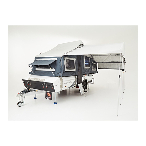
Tribe BASECAMP TRAILER User manual

TRIBE® BASECAMP TRAILER
OWNERS MANUAL
READ MANUAL & KEEP FOR YOUR RECORDS

TRIBE®BASECAMPAE
ESMAA
METRIBEBC
Congratulations on your new TRIBE®BASECAMPT. The warnings, cautions and
instructions discussed in this manual cannot cover all possible conditions and/or situations that
may occur. It is understood that the user of this expedition trailer uses common sense and
caution. Please get professional training if you are unaware on how to safely operate this
TRIBE®BASECAMPT or call us directly at 1-866-220-0171 or email us at
support@.com
If you are new at towing a trailer please go to
through the National Highway Traffic Safety Administration
https://one.nhtsa.gov/cars/problems/Equipment/towing/index.htm
M
Most States require that the railer must be registered with the DMV (Department of Motor
Vehicles) hen registering your trailer, you may need a invoice showing the urchase price
of the trailer. Be sure to request a full invoice from the dealer when making your purchase or
request one after reading this information.
TRIBETEiI
registration you will be issued a itle, I sticker and icenseplate. Please note some
states may vary in their compliance procedures these are just basic guidelines.
This is the anufacturers plate that you will have ontrailer.
Manufacturer Date
Model #
Serial #
Relevant information about the trailer

MAACESAA
The warranty period begins on the date the trailer is old to the customer
BASCAAMARETERI
The warranty coverage is 12 months on anufacturer defects only.
T covers any parts needed to correct defects in materials or workmanship of all
parts and components of each new TRIBE®BASECAMPT. Please note there will be
exclusions to this warranty.
MAACESCEAEPAS
TRIBE® Warranty parts will be sent at no charge except for tires and wheels. TRIBE®
reserves the right to make changes at any time without notice to production and
service parts in their specifications, colors, and materials, including those used in connection
with warranty repairs. For this reason, TRIBE®
CSMEMAASECEECSEPA
expeditiontR
ETRIBE®
TITEREEEREI
This warranty does not cover damage, failures or corrosion resulting from or caused by:
Failure to operate the vehicle safely in all conditions.
Misuse of the trailer or parts.
Failure of a component not covered by warranty
Damage due to terrain such as rocks, trees, ditches
Theft, vandalism, fire, or flooding
Accident, collision, abuse
AMAEAESCSMEMEACS
This warranty does not cover damage, failures or corrosion resulting from or caused by:
tone chipping, chemical fallout (acid rain), tree sap, salt,hail,windstorm,lightning, flood or
other environmental conditions that may damage the trailer.
MAEACESECEEPESE
This warranty does not cover normal maintenance services such as cleaning and polishing
wheel alignment lubricants, worn brake, shoes, drums, water tank etc.

IEBIREIRETRIBE®BASECAMPT is specially designed to be
delivered to any location that hasa forklift to lift the allet off the delivery vehicle. Once the
pallet is on level ground the metal pallet is designed to have the top removed and the two front
bars removed allowing the trailer to roll freely off the pallet.
To safely move the railer off the pallet once all of the accessories have been removed from the
packing, install the front tongue with 6 olts (see diagram). Place the draw-bar on the Trailer
Tongue and secure trailer to your vehicle. Drive vehicle forward to allow trailer to roll off the
metal pallet (make sure pallet is secure and no one is in the way of the pallet if it should move).
Once the pallet is no longer needed you can recycle the pallet or use for future storage.
NOTE :
Remove water tank / top storage draw and front torage dr - place aside forlater
installation.
Unbolt the 4 self drilled tapping screws on suppor
Using the top loops, raise top level off the pallet exposing the tongue
Tongue can be removed by cutting the wire on the front and removing 4 boltsat the
back holding it to the top pallet
Remove tongue and place aside to be used to pull trailer off the pallet
Facing the front of the trailer remove the side bar and stabilizing bars under the trailer
Remove the final side exposing the front of the trailer
ocate the bolts for the tongue located in the left middle compartmentupper
draw. The label will say "Tongue-Chassis"
Assemble the tongue to the trailer and install the itch to the tongue
All bolts and accessories will be in a separately packed brown box
Continue on next page
TIEETEIREEIETRIER
TT
RT
EREIREB

#7 Continued
Assemble ongue to railer at these bolt
locations. 1 person cannot do this
please make sure you have help.
After you have installed the ongue
install the guide wheel, hand brake
and hitch.
Connect the draw-bar onto the trailer body with the hardware in this package.
x M16*35 and 4 x M12*30.
ITTBIIE
Remove the hardware pack labeled "TBII E" and use this hardware to
install the legs onto the mounting brackets. There are four (4) leg two (2) in the front
and two (2) in the back.
Stabilizing legs can be
manually tilted up or
down. Only have in the
stabilizing position
when the trailer is
parked and being used
to camp. Never drive
with the stabilizing legs
down

ITITER
Locate hardware that is market "HITCH COUPLER"
ITEEE
Locate hardware that is market "JOCKEY WHEEL"
The "Jockey Wheel" must only be in the DOWN position to move the trailer to the ow vehicle.
When the railer has been connected to the ow ehicle Turn the crank on top to raise up the
wheel until it is off the ground and all the weight is on the ow ehicle then pull pin and move
the ockey heel into the horizontal position for towing. NEVER leave the jockey wheel
pointing towards the ground when you tow.

Before the trailer can be freed from the pallet you have to release and remove the last 4 bolts
holding the back of the trailer to the pallet. Refer to the image below for the loaction of these
bolts

Once you have installed the tongue and hitch to the car, make sure that the brake is in the
"OFF" position and you have connected the chains and electrical to your vehicle before you
attempt to drive the trailer off the pallet. Make sure there is nothing obstructing the trailer and
slowly drive the trailer off the pallet.
Make sure you do not hit the sides of the pallet and damage the trailer
Make sure that there is no one around the area that can be hurt - always think safety first
Make sure that there no obstructions in the way that the trailer will hit or over.
Drive slowly and safely when removing the trailer from the pallet.
REBETRIETETRIEREETETEITTI
You will have to install the following to complete the Trailer
•Installation of the water tank
•Installation of the front storage ompartment
•Installation of the hand brake
•Installation of the storage compartment under the roof top tent
•Installation of the roof top tent rack and awning rack.
ITITETERT
Take out the hardware that is labeled "WATER TANK"
Diagram is UPSIDE DOWN for
demonstration purposes only
DO NOT turn trailer upside
down for installation.
Place the Water Tank skid plate and two (2) steel straps on the water tank. Once done,
attach the 4 olts / washers and spring washers to the underneath of the trailer mounts as
shown in the diagram below.

ITITETREB
Take out the hardware that is labeled "TOOLBOX"
Using the hardware provided the front storage box or tool box can be fixed to the trailer by
installing the four (4) bolts to the holes shown in the diagram below.

ITITEBRE
Take out the hardware that is labeled "HAND BRAKE"
The hardware provided in the pack (M12*30 olt / M12 lat asher / M12 ock ut) will allow
you to install the hand brake onto the front of the draw-bar as shown in the picture. Move the
hand brake into the "RELEASE" or "DOWN" position.
Take out hardware labeled "CLAMP FOR HAND BRAKE"

ITITEBREBE
Pass the brake cable through the brake cable guide rings on both sides of the trailer and then
connect to the "brake cable connection plate" located on each tire ub. Use the wire clamps
as shown on each side of the "brake cable connection".
Use this type of lamp provided to secure the cable. Loop the cable provided as in picture B
and C above.
A B C
ITITETTREB
Take out the hardware that is labeled "TOP BOX"

ITTITTREB
Before the Storage Box can be installed, first remove the drawer from the top storage box as
pictured below.
Just like a regular sliding drawer, once you have the draw out press the black side lever to
unlock the sliders. Remove the drawer from the ox and place in a safe location so that it does
not get damaged. Place cardboard / paper or a moving blanket on the ground so that the paint
does not get damaged.
Use the hardware provide labeled "TOP BOX" to attach the B Frame onto the top of the
trailer as shown in the diagram below. NOTE: all holes have been "pre-drilled"

ITTITTREB
Once you have the TOP BOX ready for the storage draw, align the sliders and slide the draw
intothe sliding rails. Make sure they are aligned correctly and lock into place. Open and close at
least seven (7) times to make sure that the drawer is locked in place.
ITITETETRTRIT
Take out the hardware that is labeled "TENT BAR MOUNTING SEAT"
The hardware provided is to mount the four (4) ounting rackets provided. The location 1 - 2 -
3 - 4 on the diagram will use the M6*40 olt / M6 flat washer / M6 ock nut a total of ten (10)
holes. The location 5 - 6 - 7 - 8 will use the M6*25 olts / M6 lat asher and M6 ock ut a total
of six (6) holes.
ERIRTTB

Take out the hardware that is labeled "TENT BAR PIN"
The top bars that the roof top tent fits onto is adjustable. Use the provided pins to lock the
top bars to the base brackets. T2 ins per side are required. You are able to start in the
bottom position for travel but once rai the height of tent will allow for
wning room and adder to be used correctly.
ITITETETRTRIT
TETIITBI
TRITETIE

Take out the hardware that is labeled "AWNING BRACKET PIN"
There are two (2) parts to the awning bracket making it adjustable. Use the pins provided to
connect brackets to tent bars already installed. You can place the awning on the right or the left
depending where you are placing tent to be opened. Two (2) pins are required on each side.
TET
R
TR
TER
TE ITE
I
TR ETER

ITITETERE
You will be provided a BLUE water connection hose with a uick onnector on both sides.
Locate ubber ap protecting the water connection and remove this cap exposing
tainless uick connector.
Push in the sleeve of quick connector and plug the male end of the uick connector in until
cover closes onto the connection

To connect the water aucet when being used, remove the rubber cap as shown located
under kitchen section.
Plug in the male uick connector as shown below.
To use the water in the sink make sure there is water in the tankthe water pump has been
turn onboth quick connections are in place then the water will run freely into the sink.
NOTE: Your sink has a drain hose that must be
installed each time you use the sink to allow
water to flow into a bucket or drain onto the
ground. It will be attached to the bottom of the
sink by screwing it onto male threaded end of
sink. You will NOT be able to close the kitchen if
the drain hose is attached.

ITITETERIETETI
ITITETERIETETETI
T
R

ITITERE
We have provided you with a SOLAR PANEL plug and uick connector to make your solar
panels work with the SOLAR ready railer. The solar panel quick connector plug is located in
the back right of trailer as shown in the picture below.
Solar panel connection:Open the solar socket by rotating the plastic protection cover. Plug in
the solar connection cable. The solar connection cable will have a uick connector on the end
that can be connected to solar panels.
Attach male connector to female connector then crew on and attach solar panels.
Fit On Secure connection Screw down cap Ready for SOLAR

TB
The Two (2) burner gas stove is LP(iquid ropane) only. In the front compartment storage
there is a location to secure a 20LB ropane tank that can be used for your stove. The
stove ha independent controls for the right and left burners.
To operate the stove connect the hose and regulator provided to bottom of stove. Make
sure you do not use any plumbers tape or puttyIt is a flared connection and will s itself.
Make sure you check the connection is tight and no gas leaking ou can use Windex or
soapy water on the connection to see if there are bubbles.
Once the has been connected to the 20Lb gas ottleturn the gas on only one
and a half turns. Turn one of the valves to the left and listen to see if there is gas flowing, if
there is hit the red ignition and the gas will ignite. You can also light the gas with a
ighter.
When you have finished cooking make sure that all of the gas is turned off and you
disconnect the . Always be safe around gas it can
cause bodily and or death.
TI
This manual suits for next models
1
Table of contents
Popular Utility Vehicle manuals by other brands

Kärcher
Kärcher MC 130 manual

Metal-Fach
Metal-Fach T739 Operation instructions

Livin Lite
Livin Lite Recreational Vehicles owner's manual
Equinox Systems
Equinox Systems Explorer TRF Assembly Instructions and Operations Handbook

RHINO
RHINO S300 Manual, Operators & Parts

Sodi
Sodi Delta 900 User maintenance guide

