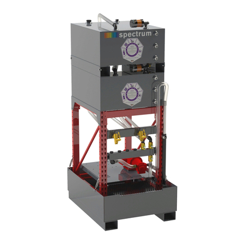
Trico Spectrum Basic 16-0037 User manual

Trico Corporation
Spectrum Oil
Storage System
Revision: 10/8/19 – 61263 D

Spectrum Oil Storage System
Page 1 | 26
TABLE OF CONTENTS
TABLE OF CONTENTS............................................................................................................................... 1
INTRODUCTION ...................................................................................................................................... 2
IMPORTANT SAFEGUARDS ...................................................................................................................... 2
PARTS LIST.............................................................................................................................................. 3
Spectrum Basic 6 Tank System, Spill Containment (P/N 16-00384) ............................................................. 3
Spectrum Spill Containment Stainless Steel 316 Tank Upgrade (P/N 16-00356)......................................... 3
Spectrum Basic 6 Tank System (P/N 16-00380) ............................................................................................ 4
Spectrum Basic 6 Tank System (P/N 16-00380) continued........................................................................... 5
ASSEMBLY INSTRUCTIONS....................................................................................................................... 7
Optional Spill Containment Pan Assembly (P/N #16-00383 or #16-00384 or #16-00385) .......................... 7
Rack Assembly (P/N 16-00356)...................................................................................................................... 9
Drip Pan & Motor Assembly ........................................................................................................................ 11
Tank Assembly.............................................................................................................................................. 13
Liquid Level Gauge Closed System Assembly .............................................................................................. 14
Pitot Tube Assembly..................................................................................................................................... 17
Valve Assembly............................................................................................................................................. 18
Hose Hook Up Assembly .............................................................................................................................. 20
Suction Tube Mounting Kit Assembly.......................................................................................................... 22
Fire Safety Protection Compliance Kit Assembly (Purchased Separately P/N #16-00357) ....................... 23
OPERATION INSTRUCTIONS................................................................................................................... 24

Spectrum Oil Storage System
Page 2 | 26
INTRODUCTION
Trico Spectrum Oil Storage Systems are an innovated solution to resolving bulk oil storage issues for
constricted space requirements. They allow expansion from the base units while eliminating contamination
issues. Storage systems come in four basic tank configurations depending on your bulk requirements. All
systems come standard with 1-1/2” Polyurethane lines and Polyethylene shutoff valves. Dispensing valves
are standard self-closing bronze with quick coupling adapters for tank filling. A single drip tray is provided to
contain spillage from valve assemblies while dispensing. The motor and pump combination draw less than
14.5 amps allowing the system to be placed on a 15-amp circuit. The bronze gear pump is positive
displacement and self-priming. Optional spill containment is available that exceeds the requirements set by
EPA standards.
Fluid Capacity per Tank
65 Gallons
Sight Gauge
Brass
Pump Head
Bronze Gear
Motor
1-1/2 HP TEFC, 4.5 GPM
Amp Draw @ Max Load
14.5 A
Voltage
110 / 220 V
Containment Capacity (sold separately)
>110% per Spill Container
Tank Lines
1-1/2” Polyurethane
Tank Shut Off Valves
Polyethylene
Valve Assembly
Self-Closing 1” Bronze
IMPORTANT SAFEGUARDS
1. Read Instructions
All safety and operating instructions should be read before using the Spectrum Oil Storage System.
2. Retain Instructions
Safety and operating instructions should be retained for future reference.
3. Heed Warnings
All warnings on the product and in the operating manual should be adhered to.
4. Follow Instructions
All operating instructions should be followed.
Warning: Do not store products with flashpoint below 150°F or a product with a pH
below 3. Storing unapproved products can result in serious bodily injury or death and will
void any product warranty.

Spectrum Oil Storage System
Page 3 | 26
PARTS LIST
Trico goes to great lengths to ensure all your parts are shipped correctly, please make sure you check to see
that all your parts are there prior to assembling your System.
These instructions cover the following part numbers:
•Spectrum Basic 4 Tank System, Spill Containment (P/N 16-00379 or 36781)
•Spectrum Basic 6 Tank System, Spill Containment (P/N 16-00380 or 36782)
•Spectrum Basic 8 Tank System, Spill Containment (P/N 16-00381 or 36783)
•Spectrum Basic 12 Tank System, Spill Containment (P/N 16-00382 or 36784)
However, the parts list displayed is for a 6 Tank System, so the quantities will differ on some components for
the different number of Tanks.
Spectrum Basic 6 Tank System, Spill Containment (P/N 16-00384)
Part Number
Description
Quantity
Unit
6 Wide Containment Pan Assembly
729002 – Black
Tank Assembly 65 Gallon - Steel 2" Off Set Grey
4
Each
385004
Grating Galvanized 16.38” X 49.5” - #3 Gauge
2
Each
385005
Grating Galvanized 29.38” X 49.5” - #3 Gauge
1
Each
Assembly Items in Bag
307007
Pipe Nut 3/4” – Black Pipe
12
Each
311046
Close Nipple 3/4” X 1-1/2” Black Pipe
8
Each
313015
Turn Buckle 3/8” X 16” Hook to Hook
4
Each
318002
Gasket Buna-N 1” thick
16
Each
328000
Pipe Cap 3/4” Black Pipe
4
Each
363008
Screw #8 X 3/4” Self-Tapping Phillip Pan Head
2
Each
740127
Bracket 12 A 1 Hole 2.0 X 10.85 2B
2
Each
Spectrum Spill Containment Stainless Steel 316 Tank Upgrade (P/N 16-00356)
Part Number
Description
Quantity
Unit
Painted Grey / Comes with Two ¾” Square Head Plugs
Tank Assembly 65 gallon – Stainless Steel 2" Off Set Grey
6
Each
Stainless Steel Square Head Plugs - 3/4" MNPT
12
Each

Spectrum Oil Storage System
Page 4 | 26
Spectrum Basic 6 Tank System (P/N 16-00380)
Part Number
Description
Quantity
Unit
6 – Tanks
710066-T
Tank Assembly 65 Gallon - Steel 2" Off Set Gray
3
Each
Frame Parts
301000 – Black
Upright Frame 32" x 84" Series 2000 - Black
2
Each
326003 – Black
Beam Step 3.5" x 70" Series 2000 - Black
4
Each
327002 – Black
Beam Channel 70" - Series 2000 - Black
2
Each
733002 – Black
Double Wide Drip Pan 70" Black
1
Each
385002
Screen Steel (2 x 2 Mesh) 12" 24.5" LG
2
Each
2 Each – Beam Channel Mounting Part Bag (per bag contents)
307006
Nut 3/8" - 16 Lock Serrated
2
Each
363004
Bolt 3/8" - 16 x 1"
2
Each
6 Each – Poly Container Shutoff Kits #788001 (per bag contents)
314006
3/4" Plug
1
Each
346004
Hose Clamp
1
Each
315013
Poly Hose Barb
1
Each
365067
1-1/2” Poly Ball Valve
1
Each
311013
1-1/2” Poly Close Nipple
2
Each
310056
1-1/2" Poly Elbow
1
Each
541096
Container Bracket
1
Each
1 Each – Suction Hose Hanger Kits #745000 (per bag contents)
307006
3/8" - 16 Lock Serrated
3
Each
307013
#8 - 32 Hex Nut
2
Each
359007
Conduit Clamp 2-B
2
Each
363004
3/8" - 16 x 1" Bolt
3
Each
363007
Screw Round Head #8 - 32 x 1" Zinc Plated
2
Each
1 Each – Discharge Hose Hanger Kits #745000 (per bag contents)
307006
3/8" - 16 Lock Serrated
1
Each
307013
#8 - 32 Hex Nut
1
Each
359007
Conduit Clamp 2-B
1
Each
363004
3/8" - 16 x 1" Bolt
1
Each
363007
Screw Round Head #8 - 32 x 1" Zinc Plated
1
Each
541070
Bracket - Suction Tube Upper
1
Each
2 Each – Pan Drip ¾ FLG Kit #733004 (per bag contents)
307006
3/8" - 16 Lock Serrated
4
Each
310043
3/4” 90 Degree Elbow
1
Each
311018
Close Nipple 3/4” X 3” Black Pipe
1
Each
316001
3/4" Self-Closing Faucet
1
Each
363004
3/8" - 16 x 1" Bolt
4
Each
1 Each – Individually Boxed Motors
741057
Transfer Units 1.5 HP with Timer
1
Each

Spectrum Oil Storage System
Page 5 | 26
Spectrum Basic 6 Tank System (P/N 16-00380) continued
1 Each – Transfer Unit and Tier Mounting Bags (per bag contents)
307006
3/8" - 16 Lock Serrated
4
Each
309004 Washer Neoprene 1" O.D. x .438 I. D. x .25 4 Each
309005 Washer, Flat 3/8” Zinc Plated 4 Each
363004 3/8" - 16 X 1" Bolt 4 Each
745005 Discharge Hose Assembly 5 Total
745006
Suction hose Assembly
6
Total
748001
Valve Assembly with 1-1/2” Valves
6
Total
325003
1-1/2” Polyspring Hose
30
Feet
6 Each – Valve Arrangement Parts Bag Discharge #787001 (per bag contents)
346004
Hose Clamp
1
Each
310056
1-1/2" Poly Elbow
1
Each
315013 Poly Hose Barb 1 Each
6 Each – Tank LLG Breather System
20002 Liquid Level Gauge Closed System Assembly 1 Each
39141 EX - 50 Desiccant Breathers 1 Each
36217
Pitot Tube 1/4" NPTM - 12" SST with Adapter 16031
1
Each
10592
Bushing Reducer 3/4" x 1/4"
1
Each
36133
Pitot Tube Sampler Adapter - 1/4"
1
Total
1 Each – Marking Kits – Tags and Tank Labels
16222
10 label colors for Tanks and LLG's
(10 x 1)
Each
Fill Indicator Decal
4
Each
37075-84
10 ID Tags Colors for MISC
(10 x 1)
Each
61263
Instructions for Basic System Assembly
1
Each

Spectrum Oil Storage System
Page 6 | 26
Spectrum 6 Tank System Fire Safety Kit (P/N 16-00357) - UPGRADE ITEM
Item #
Part #
Description
Quantity
Unit
6 - Fire Safety Compliance Parts List (#16-00357)
1
100000065
65 Gallon Spectrum Container
1
Each
2
20002
Liquid Level Gauge Closed System Assembly
1
Each
3
310046
90 Degree Elbow 1-1/2” NPT
2
Each
4
365039
Steel 1-1/2” Valve
1
Each
5
300003
Reducer Bushing 2” x 1-1/2” NPT
1
Each
6
311014
1-1/2” NPT Close Nipple
4
Each
7
727125
1-1/2” Steel hose Assembly
1
Each
8
313011
1-1/2” NPT Union
2
Each

Spectrum Oil Storage System
Page 7 | 26
ASSEMBLY INSTRUCTIONS
Optional Spill Containment Pan Assembly (P/N #16-00383 or #16-00384 or #16-00385)
Note: If you purchased the Optional Spill Containment Assembly, this should be the first
item to be assembled.
Items Needed for Assembly:
Part Number
Description
Quantity
Unit
3 – Pan Assemblies Wide System
729002 – Black
Tank Assembly 65 Gallon - Steel 2" Off Set Grey
3
Each
385004
Grating Galvanized 16.38” X 49.5” - #3 Gauge
2
Each
385005
Grating Galvanized 29.38” X 49.5” - #3 Gauge
1
Each
Assembly Items in Bag
307007
Pipe Nut ¾” – Black Pipe
12
Each
311046
Close Nipple ¾” X 1-1/2” Black Pipe
8
Each
313015
Turn Buckle 3/8” X 16” Hook to Hook
4
Each
318002
Gasket Buna-N 1” thick
16
Each
328000
Pipe Cap ¾” Black Pipe
4
Each
363008
Screw #8 X 3/4” Self-Tapping Phillip Pan Head
2
Each
740127
Bracket 12 A 1 Hole 2.0 X 10.85 2B
2
Each
Assembly Instructions:
1. Optional Spill Containment Pans should be laid out and assembled in the location in which the unit
will be located. Once the pans are assembled together, they are difficult to move around by hand.
2. Set each Spill Containment Pan side by side by aligning the two holes located on each side.
3. Using the Spill Containment Pan Fitting Kit, located with the pans, to fasten the pans together by
inserting the 3/4" pipe nipple through the hole.
4. For interior connections, place one rubber gasket on each side of the 3/4" pipe nipple and then
thread a pipe nut onto each side of the pipe nipple (see Image 1).
5. Tighten the pipe nuts using two pipe wrenches until the rubber gaskets make a watertight seal. Do
not over tighten the nuts as this will extrude the gaskets around the nuts. If this happens back the
nut off.
6. For the four outside holes in the Spill Containment Pans, place one rubber gasket on each side of
the 3/4" pipe nipple and then thread a pipe nut onto the pipe nipple located inside the pan. Use the
four pipe caps threading them onto the end of the pipe nipple located on the outside of the pan.
Tighten the fittings in the same manner as the ones on the interior (see Image 2).
7. Set the metal grating from the Spill Containment Pans to the side until the Storage System is fully
assembled. You will need to place the rack into the Spill Containment Pans and adjust the turn
buckles before placing the galvanized grating.

Spectrum Oil Storage System
Page 8 | 26
Image 1
Image 2

Spectrum Oil Storage System
Page 9 | 26
Rack Assembly (P/N 16-00356)
Note: Assembly of the Racking components can be done outside of the Spill Containment
Pans. After the Racking is assembled, lift the Racking into the Spill Containment Pans
before mounting tanks and motors.
Items Needed for Assembly:
Part Number
Description
Quantity
Unit
Frame Parts
301000 – Black
Upright Frame 32" x 84" Series 2000 - Black
2
Each
326003 – Black
Beam Step 3.5" x 70" Series 2000 - Black
4
Each
Assembly Instructions:
1. Determine the location of the tank system and measure the length, width and height to ensure that
the system is not obstructed. The minimum distance the tanks must remain from a wall surface is 12
inches.
2. Remove all components and hardware from boxes and lay them for easy identification and
inventory. Assembly of the system will take two people.
3. Gather the frame sides and crossbeam members form the shipping pallet and stand one of the ends
upright. Measure 50” from the ground and find the nearest keyhole slot. Measure and mark the
other frame side in the same locations for the front and back crossbeam.
4. Insert one of the crossbeams with channel facing up into the keyhole slot on the side frame and
place the other end into the keyhole slot on the other frame.
5. Crossbeams are equipped with safety locks that snap into place locking the cross beam onto the
side frame. Ensure that the safety locks are fully engaged. A small rubber or plastic mallet may be
needed to properly engage the crossbeams.
6. Measure 78” from the ground and find the next set of keyhole slots for the second crossbeam
location. Measure and mark the other frame side in the same locations for the front and back
crossbeam.
7. Insert the second set of cross beams with the channel facing up into the keyholes and lock tabs into
place (this may take a small plastic mallet to knock into place).
Image 3
50”
78”

Spectrum Oil Storage System
Page 10 | 26
8. Lift the assembled racking into the Spill Containment Pans centering the racking so that the front
valve pan does not stick out past the Spill Containment Pan.
9. Use the turn buckles provided in the Spill Containment Pan Kit to secure the racking to the Spill
Containment Pan by placing one end of the turn buckle into the hole on the side lip of the Spill
Containment Pan (see Image 4).
313015
Turn Buckle 3/8” X 16” Hook to Hook
4
Each
Image 4
10. Attach bracket to the middle of the containment pan on each end of the system using the self-tapping
screws (see Image 5). Then fasten the brackets to the floor (hardware not provided)
363008
Screw #8 X 3/4” Self-Tapping Phillip Pan Head
2
Each
740127
Bracket 12 A 1 Hole 2.0 X 10.85 2B
2
Each
Image 5

Spectrum Oil Storage System
Page 11 | 26
Drip Pan & Motor Assembly
Items Needed for Assembly:
Part Number
Description
Quantity
Unit
Frame Parts
327002 – Black
Beam Channel 70" - Series 2000 - Black
2
Each
733002 – Black
Double Wide Drip Pan 70" Black
1
Each
385002
Screen Steel (2 x 2 Mesh) 12" 24.5" LG
2
Each
2 Each – Beam Channel Mounting Part Bag (per bag contents)
307006
Nut 3/8" - 16 Lock Serrated
2
Each
363004
Bolt 3/8" - 16 x 1"
2
Each
2 Each – Pan Drip ¾ FLG Kit #733004 (per bag contents)
307006
3/8" - 16 Lock Serrated
4
Each
310043
3/4” 90 Degree Elbow
1
Each
311018
Close Nipple 3/4” X 3” Black Pipe
1
Each
316001
3/4" Self-Closing Faucet
1
Each
363004
3/8" - 16 x 1" Bolt
4
Each
1 Each – Individually Boxed Motors
741057
Transfer Units 1.5 HP with Timer
1
Each
1 Each – Transfer Unit and Tier Mounting Bags (per bag contents)
307006
3/8" - 16 Lock Serrated
4
Each
309004
Washer Neoprene 1" O.D. x .438 I. D. x .25
4
Each
309005
Washer, Flat 3/8” Zinc Plated
4
Each
363004
3/8" - 16 X 1" Bolt
4
Each
Assembly Instructions:
1. Mark the location of the drip pan so the top of the drip pan is 17” from the ground.
2. Assemble the drip pan drain assembly by threading together with a 90-degree elbow, a 3/4” pipe
nipple and the drain faucet.
3. Thread the faucet assembly into the drain hole location on the bottom of the drip pan.
4. Use the hardware provided to mount to drip pan to its location.
5. Place the small grates into the drip pan.
6. A certified electrician should wire the motor using the NEMA wiring diagram located on the
faceplate of the motor and make electrical connections in adherence to all regulation codes and
standards. If using the provided switch, ensure the overload relay is wired into the toggle switch.
7. Determine where the electrical switch will be located. The switch can be mounted to the tank
support beams or existing bulkhead or panel with self-taping sheet metal screws (not provided).
Keep in mind that the location of the switches should not exceed the cord length provided.
8. It is easier to wire each motor before mounting them to the motor pan assembly.
9. Using the bolt hardware pack (Transfer Unit and Tier Mounting Bags) mount the pump and motor
assembly to the far-right side of the drip pan for the motor fasteners on the channel track of the
pan should be left loose, until the tank assemblies are in place, so that motors can be centered
under each tank. Please remember to go back and tighten them up after tank placement. (see
Image 6)

Spectrum Oil Storage System
Page 12 | 26
10. Mount the timer switch to the inside leg of the tank rack just above the motor and below the valve
crossbeam. Use the hardware provided in the kit (see Image 6).
11. Connect the discharge line to the outlet of the pump, securing it with a hose clamp.
Image 6

Spectrum Oil Storage System
Page 13 | 26
Tank Assembly
Items Needed for Assembly:
Part Number
Description
Quantity
Unit
6 Each – Poly Container Shutoff Kits #788001 (per bag contents)
346004
Hose Clamp
1
Each
315013
Poly Hose Barb
1
Each
365067
1-1/2” Poly Ball Valve
1
Each
311013
1-1/2” Poly Close Nipple
2
Each
310056
1-1/2" Poly Elbow
1
Each
541096
Container Bracket
1
Each
Assembly Instructions:
1. Thread the ball valve assemblies together with thread sealer using the 1-1/2” polyethylene fittings.
The order is close nipple, 90 elbow, close nipple, ball valve, 1-1/2 hose barb. (see Image 7)
2. Assemble the ball valve assembly into the large hole on the bottom of the tank by placing the tank
clip through the assembly and threading the assembly to the tank. The tank containment brackets
will keep the tank from sliding from the crossbeam when placed onto the rack.
Image 7

Spectrum Oil Storage System
Page 14 | 26
Liquid Level Gauge Closed System Assembly
Items Needed for Assembly:
Image 8
Liquid Level Gauge Parts List
Item # Part # Description Quantity
1
14-00212
Gasket Drum ¾” NPT LLG Fitting 1
2
14-00261
Drum 3/4 Bung Adapter w/o Kidney loop
1
3
13058
5/8" OUTER DIA GASKET 2
4
13067
Liquid Level Sight Gauge 3/4" x 27”
1
5
13001
Liquid Level Sight Glass 5/8" x 27” 1
6
13218
3/4" x 3/8” Brass Adapter
1
7
10530
#4 JIC to 1/8" Elbow Steel Adapter 1
8
10319
#4 JIC to 1/8" Straight Steel Adapter
2
9
20-00548
1/2" to 1/8" Brass Bushing 1
10
10531
1/2" x 1/2" x 3/4"Brass Tee
1
11
16147
1/2" Brass Hex Nipple 1
12
16221
3/4" Brass Nipple
1
13
16-00367
15" Stainless-Steel Braided Flex Line 1
14
10256
3/4" Steel Pipe Plug
1
15
14-00242
3/4-18 NPT Brass Hex Plug (OPTIONAL) 1

Spectrum Oil Storage System
Page 15 | 26
Assembly Instructions:
1. Position the tanks vertically with the two 3/4" bungs on the front face facing upward, vent hole
should point to top of the tank. Top of tank only has one 3/4" NPT hole.
2. Thread 3/4" Steel Pipe Plug (Part 14) into upper tank fitting using hydraulic thread sealant.
3. Remove the Liquid Level Gauge (LLG) assembly from package and hand thread the 3/4" NPT Bung
Adapter (Part 2) thru the Drum Gasket (Part 1) and into the lower tank bung.
Note: It may be easier to thread the 3/4” NPT Bung Adapter (Part 2) into the tank if the Liquid
Level Gauge assembly is disassembled – follow Step 4 in reverse to disable the LLG assembly.
4. LLG Assembly – to the Lower Tank Bung (Part 2)
a. Sight Guard (Part 4) Screwed into Lower Tank Bung (Part 2) facing view side out. DO NOT
USE thread sealant on the Sight Guard
b. Take Sight tube (Part 5) and place Gasket (Part 3) to both ends of tube. To affix to the glass,
remove the Gasket protective white cover, this will hold it to top and bottom the glass tube.
c. Slide the Sight tube (Part 5) into Sight Guard (Part 4).
d. Thread the Brass Adapter (Part 6) on to the top of Sight Guard (Part 4). DO NOT USE thread
sealant on the Brass Adapter
e. Thread the #4 JIC Steel Elbow (Part 7) onto the Brass Adapter (Part 6).
5. Tighten the LLG assembly using an adjustable wrench to turn the Lower Bung Fitting and orientate
the LLG to the vertical 12 o'clock position aligning it with the upper tank fitting in front of the steel
plug.
Note: Use Adjustable Wrench while tightening the lower bung / pressing on the LLG will result
in the glass tubing breaking. Do not use the LLG for leverage in Tightening the lower bung.
6. If no sample port/pitot tube was purchased to sample oil from the tank, install 3/4” Brass Plug (Part
15) into Lower Bung (Part 2). Otherwise the 3/4" Brass Plug is not included with this kit.
7. Install the Tee Breather Assembly onto the top of the tank into the 3/4" vent hole using hydraulic
thread sealant. Make sure the #4 JIC Steel Straight Adapter (Part 8) faces toward the #4 JIC Steel
Elbow (Part 7) on top of the LLG Assembly. (see Image 9)
Image 9
Note the orientation
of the Adapters

Spectrum Oil Storage System
Page 16 | 26
8. Find and install the Stainless-Steel Braided Line (Part 13) and one end to the #4 JIC Steel Straight
Adapter (Part 8) and the other end to the #4 JIC Steel Elbow (Part 7). (see Image 10)
9. Find and install the Desiccant Breather (#39141) onto the 1/2" Brass Hex Nipple (Part 11). (see
Image 10)
Image 10
10. Using the Spectrum color coding system, determine what colors will be used to determine the
different oil types. Place the color-coded sticker onto the front of the tank.
11. Place the matching color-coded tag onto each valve making sure that the valve and tank are correct.
Decals and tags can be written on to identify the tank contents.
Note: Make sure colors, and tags, are where you want them to identify the products.
Image 11
12. Place your tanks on upper beams and finish by connecting hoses to the discharge and suction
valves.
13. Please remember to tighten down the motors if you have not done so, after evenly spacing tanks
and motors.

Spectrum Oil Storage System
Page 17 | 26
Pitot Tube Assembly – UPGRADE ITEM
Items Needed for Assembly:
Pitot Tube (items from Liquid Level Gauge Parts List already installed)
Item # Description Quantity
14-00261
Drum 3/4 Bung Adapter w/o Kidney loop 1
36217 Pitot Tube 1/4" NPTM - 12" SST with Adapter 16031 1
36133 Pitot Tube Sampler Adapter - 1/4" 1
10592
Bushing Reducer 3/4" x 1/4"
1
Assembly Instructions:
1. Sampling Pitot Tubes (Sample Ports) (#36217) get installed through the Liquid Level Gauge.
2. Remove 3/4 Brass Hex Plug (#14-00261) from Drum Bung Adapter (#14-00242).
3. Install Bushing Reducer 3/4" X 1/4" Reducer (#20592) into Drum Bung Adapter (#14-00242) and use
hydraulic thread sealer when installing the Reducer Bushing.
4. Thread in Sample Port Pitot Tube (#36217) using hydraulic thread sealer. (see Image 12)
5. To take sample, use Pitot Tube Sampler Adapter (#36133) and attach a 1/4" OD tube to the barb to
retrieve sample.
Image 12

Spectrum Oil Storage System
Page 18 | 26
Valve Assembly
Items Needed for Assembly:
Frame Parts
327002 – Black
Beam Channel 70" - Series 2000 - Black
2
Each
2 Each – Beam Channel Mounting Part Bag (per bag contents)
307006
Nut 3/8" - 16 Lock Serrated
2
Each
363004
Bolt 3/8" - 16 x 1"
2
Each
4 Each – Valve Arrangement Parts Bag Discharge (per bag contents)
346004
Hose Clamp
1
Each
310056
1-1/2" Poly Elbow
1
Each
315013
Poly Hose Barb
1
Each
748001
Valve Assembly with 1-1/2” Valves
6
Total
Assembly Instructions:
1. Measure the location of the tank valve crossbeam at a height of 39” from the ground. (see Image
13)
2. Mount the tank valve crossbeam into location using the available hardware placing the channel
inward.
3. Place the tank valve assemblies onto the crossbeam by rotating the locking lug horizontal and
inserting the valve assembly into the crossbeam.
4. Position the first set of valve assemblies to the further left and rotate the locking lug to the vertical
position.
5. Keeping the locking lug in the vertical position tighten the bolt at the back of the locking lug unit
tight. (see Image 14)
6. Repeat steps for the rest of the valve assemblies.
7. Thread the 90-degree elbow to the top of each valve and seal with thread sealant.
8. Thread a hose barb into the 90-degree elbow on the valve assembly and seal with thread sealant.

Spectrum Oil Storage System
Page 19 | 26
Image 13
Image 14
This manual suits for next models
7
Table of contents
Other Trico Storage manuals
